Configuring Pseudowire

Cisco Pseudowire Emulation Edge-to-Edge (PWE3) allows you to transport traffic using traditional services such as E1/T1 over a packet-based backhaul technology such as MPLS or IP. A pseudowire (PW) consists of a connection between two provider edge (PE) devices that connects two attachment circuits (ACs), such as ATM VPIs/VCIs or E1/T1 links.

Understanding Pseudowires

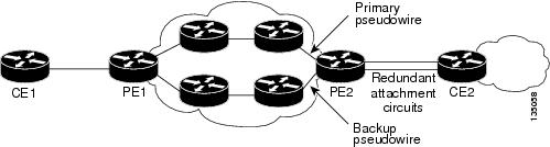
Pseudowires (PWs) manage encapsulation, timing, order, and other operations in order to make it transparent to users; the PW tunnel appears as an unshared link or circuit of the emulated service.

There are limitations that impede some applications from utilizing a PW connection.

Cisco supports the following standards-based PWE types:

Structure-Agnostic TDM over Packet

SAToP encapsulates TDM bit-streams (T1, E1, T3, E3) as PWs over PSNs. It disregards any structure that may be imposed on streams, in particular the structure imposed by the standard TDM framing. The protocol used for emulation of these services does not depend on the method in which attachment circuits are delivered to the PEs. For example, a T1 attachment circuit is treated the same way for all delivery methods, including: PE on copper, multiplex in a T3 circuit, mapped into a virtual tributary of a SONET/SDH circuit, or carried over a network using unstructured Circuit Emulation Service (CES). Termination of specific carrier layers used between the PE and circuit emulation (CE) is performed by an appropriate network service provider (NSP).

For instructions on how to configure SAToP, see Configuring Structure-Agnostic TDM over Packet.

For a sample SAToP configuration, see Configuration Examples for Pseudowire.

Structure-Aware TDM Circuit Emulation Service over Packet-Switched Network

CESoPSN encapsulates structured (NxDS0) TDM signals as PWs over PSNs.

Emulation of NxDS0 circuits saves PSN bandwidth and supports DS0-level grooming and distributed cross-connect applications. It also enhances resilience of CE devices due to the effects of loss of packets in the PSN.

For instructions on how to configure CESoPSN, see Configuring Circuit Emulation Service over Packet-Switched Network.

For a sample CESoPSN configuration, see Configuration Examples for Pseudowire.

Transportation of Service Using Ethernet over MPLS

Ethernet over MPLS (EoMPLS) PWs provide a tunneling mechanism for Ethernet traffic through an MPLS-enabled Layer 3 core network. EoMPLS PWs encapsulate Ethernet protocol data units (PDUs) inside MPLS packets and use label switching to forward them across an MPLS network. EoMPLS PWs are an evolutionary technology that allows you to migrate packet networks from legacy networks while providing transport for legacy applications. EoMPLS PWs also simplify provisioning, since the provider edge equipment only requires Layer 2 connectivity to the connected customer edge (CE) equipment. The Cisco ASR 901 implementation of EoMPLS PWs is compliant with the RFC 4447 and 4448 standards.

For instructions on how to create an EoMPLS PW, see Configuring Transportation of Service Using Ethernet over MPLS.

Limitations

  • When configuring an EoMPLS pseudowire on the Cisco ASR 901 , you cannot configure an IP address on the same interface as the pseudowire.

  • Layer 2 Tunneling Protocol, version 2 and 3 (L2TPv2 and L2TPv3) is not supported on the Cisco ASR 901 series routers.

  • The maximum number of CEM groups supported under each controller is four.

Hot Standby Pseudowire Support for ATM/IMA

The Hot Standby Pseudowire Support for Inverse Multiplexing over ATM (IMA) feature improves the availability of pseudowires by detecting failures and handling them with minimal disruption to the service. This feature allows the backup pseudowire to be in a “hot standby” state, so that it can immediately take over if the primary pseudowire fails.

A backup pseudowire is provisioned and corresponding entries are populated to hardware tables. When the primary pseudowire goes down, the backup pseudowire is used to switch the packets.

This feature supports the following transport types:

  • ATM AAL5 in VC mode

  • ATM in VP mode

  • ATM in port mode

Configuring Pseudowire

This section describes how to configure pseudowire on the Cisco ASR 901 . The Cisco ASR 901 supports pseudowire connections using CESoPSN. The following sections describe how to configure pseudowire connections.

For full descriptions of each command, see the Cisco ASR 901 Series Aggregation Services Command Reference Guide.

For pseudowire configuration examples, see Configuration Examples for Pseudowire.

Configuring Pseudowire Classes

A pseudowire class allows you to create a single configuration template for multiple pseudowire connections. You can apply pseudowire classes to all pseudowire types.

Complete the following steps to configure a pseudowire class:

Procedure

  Command or Action Purpose
Step 1

enable

Example:


Router> enable

Enables privileged EXEC mode.

  • Enter your password if prompted.
Step 2

configure terminal

Example:


Router# configure terminal

Enters global configuration mode.

Step 3

pseudowire-class class-name

Example:


Router(config)# pseudowire-class newclass

Creates a new pseudowire class.

Step 4

encapsulation mpls

Example:


Router(config-pw-class)# encapsulation mpls

Sets an encapsulation type.

Step 5

interface cem slot/port

Example:


Router(config)# interface cem0/0

Configures the pseudowire interface to use for the new pseudowire class. This example shows a CESoPSN interface.

Step 6

cem group-number

Example:


Router(config-if)# cem 0

Defines a CEM channel.

Step 7

xconnect ip pw-class pseudowire-class

Example:


Router(cfg-if-cem)# xconnect 1.1.1.1 40 pw-class myclass

Binds an attachment circuit to the CESoPSN interface to create a CESoPSN pseudowire. Use the pw-class parameter to specify the pseudowire class that the CESoPSN pseudowire interface uses.

What to do next


Note

You cannot use the encapsulation mpls parameter with the pw-class parameter.

Note

The use of the xconnect command can vary depending on the type of pseudowire you configure.

Configuring CEM Classes

A CEM class allows you to create a single configuration template for multiple CEM pseudowires.


Note

Cisco IOS release 15.3(3)S automatically enables forward-alarm ais configuration (under the config-controller configuration mode). To disable this configuration, use the no forward-alarm ais command.
  • The forward-alarm ais configuration is applicable only for CESoP. It is not supported for SAToP.
  • You must run the no forward-alarm ais command before using CESoP with controllers in loopback (either through loopback command under controller or by using a physical loopback jack).
  • Though the forward-alarm ais command (and its no form) was not supported in previous releases, the Cisco ASR 901 router behaved as if this command was configured under the controller interface.

Complete the following steps to configure a CEM class:

Procedure

  Command or Action Purpose
Step 1

enable

Example:


Router> enable

Enables privileged EXEC mode.

  • Enter your password if prompted.
Step 2

configure terminal

Example:


Router# configure terminal

Enters global configuration mode.

Step 3

class cem cem-class-name

Example:


Router(config)# class cem mycemclass

Creates a new CEM class

Step 4

payload-size size

Example:


Router(config-cem-class)# payload-size 512

Specifies the payload for the CEM class.

Step 5

dejitter-buffer size

Example:


Router(config-cem-class)# dejitter-buffer 10

Specifies the dejitter buffer for the CEM class.

Step 6

idle-pattern size

Example:


Router(config-cem-class)# idle-pattern 0x55

Specifies the idle-pattern for the CEM class.

Step 7

exit

Example:


Router(config-cem-class)# exit

Returns to the config prompt.

Step 8

interface cem slot/port

Example:


Router(config)# interface cem 0/0

Configure the CEM interface that you want to use for the new CEM class.

Note 
The use of the xconnect command can vary depending on the type of pseudowire you are configuring.
Step 9

no ip address

Example:


Router(config-if)# no ip address

Disables the IP address configuration for the physical layer interface.

Step 10

cem group-number

Example:


Router(config-if)# cem 0

Enters the CEM configuration mode.

Step 11

cem class cem-class-name

Example:


Router(config-if-cem)# cem class mycemclass

Specifies the CEM class name.

Step 12

xconnect ip-address encapsulation mpls

Example:


Router(config-if-cem)# xconnect 10.10.10.10 200 encapsulation mpls

Binds an attachment circuit to the CEM interface to create a pseudowire

Configuring a Backup Peer

A backup peer provides a redundant pseudowire (PW) connection in the case that the primary PW loses connection; if the primary PW goes down, the Cisco ASR 901 diverts traffic to the backup PW.

Complete the following steps to configure a backup peer:

Procedure

  Command or Action Purpose
Step 1

enable

Example:


Router> enable

Enables privileged EXEC mode.

  • Enter your password if prompted.
Step 2

configure terminal

Example:


Router# configure terminal

Enters global configuration mode.

Step 3

interface name slot/port

Example:


Router(config)# interface cem0/0

Configures the pseudowire interface to use for the new pseudowire class.

Step 4

cem group-number

Example:


Router(config-if)# cem 0

Defines a CEM channel.

Step 5

xconnect peer-loopback-ip-address encapsulation mpls

Example:


Router(config-if-cem)# xconnect 10.10.10.20 encapsulation mpls

Binds an attachment circuit to the CEM interface to create a pseudowire.

Step 6

backup peer peer-router-ip-address vcid [pw-class pw-class-name]

Example:


Router(config-if-cem-xconn)# backup peer 10.10.10.12 10 344

Defines the address and VC of the backup peer.

Step 7

backup delay enable-delay [disable-delay | never ]

Example:


Router(config-if-cem-xconn)# backup delay30 never 

Specifies the delay before the router switches pseudowire traffic to the backup peer VC.

Where:

  • enable-delay —Time before the backup PW takes over for the primary PW.
  • disable-delay —Time before the restored primary PW takes over for the backup PW.
  • never —Disables switching from the backup PW to the primary PW.

Configuring Structure-Agnostic TDM over Packet

Complete the following steps to configure Structure-Agnostic TDM over Packet (SAToP) on the Cisco ASR 901:

Procedure

  Command or Action Purpose
Step 1

enable

Example:


Router> enable 

Enables privileged EXEC mode.

  • Enter your password if prompted.
Step 2

configure terminal

Example:


Router# configure terminal

Enters global configuration mode.

Step 3

controller {t1|e1} slot/port

Example:


Router(config)# controller t1 0/4

Configures the T1 or E1 interface.

Step 4

cem-group group-number unframed

Example:


Router(config-if)# cem-group 4 unframed

Assigns channels on the T1 or E1 circuit to the CEM channel. This example uses the unframed parameter to assign all the T1 timeslots to the CEM channel.

Step 5

interface cem slot/port

Example:


Router(config)# interface cem 0/4

Configures the pseudowire interface to use for the new pseudowire class.

Step 6

no ip address

Example:


Router(config)# no ip address

Disables the IP address configuration for the physical layer interface.

Step 7

cem group-number

Example:


Router(config-if)# cem 4

Defines a CEM group.

Step 8

xconnect ip-address encapsulation mpls

Example:


Router(config-if-cem)# xconnect 30.30.30.2 304 encapsulation mpls

Binds an attachment circuit to the CEM interface to create a pseudowire. This example creates a pseudowire by binding the CEM circuit 304 to the remote peer 30.30.2.304.

Step 9

exit

Example:


Router(cfg-if-cem-xconn)# exit

Exits configuration mode.

What to do next


Note

When creating IP routes for a pseudowire configuration, we recommend that you build a route from the xconnect address (LDP router-id or loopback address) to the next hop IP address, such as ip route 30.30.30.2 255.255.255.255 1.2.3.4 .

Configuring a SAToP Pseudowire with UDP Encapsulation

Complete the following steps to configure a SAToP pseudowire with UDP encapsulation:

Procedure
  Command or Action Purpose
Step 1

enable

Example:

Router> enable

Enables privileged EXEC mode.

Enter your password if prompted.

Step 2

configure terminal

Example:

Router# configure terminal

Enters global configuration mode.

Step 3

pseudowire-class pseudowire-class-name

Example:

Router(config)# pseudowire-class udpClass

Creates a new pseudowire class.

Step 4

encapsulation udp

Example:

Router(config-pw-class)# encapsulation udp

Specifies the UDP transport protocol.

Step 5

ip local interface loopback interface-number

Example:

Router(config-pw-class)# ip local interface Loopback 1

Configures the IP address of the provider edge (PE) router interface as the source IP address for sending tunneled packets.

Step 6

ip tos value value-number

Example:

Router(config-pw-class)# ip tos value 100

Specifies the type of service (ToS) level for IP traffic in the pseudowire.

Step 7

ip ttl number

Example:

Router(config-pw-class)# ip ttl 100

Specifies a value for the time-to-live (TTL) byte in the IP headers of Layer 2 tunneled packets.

Step 8

controller {e1 | t1} slot/port

Example:

Router(config)# controller [e1|t1] 0/0

Enters E1/T1 controller configuration mode.

Step 9

cem-group group-number unframed

Example:
Router(config-controller)# cem-group 4 unframed

Assigns channels on the T1 or E1 circuit to the CEM channel. This example uses the unframed parameter to assign all the T1 timeslots to the CEM channel.

Step 10

exit

Example:

Router(config-controller)# exit

Exits controller configuration.

Step 11

interface cem slot/port

Example:

Router(config)# interface CEM0/4

Selects the CEM interface where the CEM circuit (group) is located (where slot/subslot is the SPA slot and subslot and port is the SPA port where the interface exists).

Step 12

no ip address

Example:

Router(config)# no ip address

Disables the IP address configuration for the physical layer interface.

Step 13

cem group-number

Example:

Router(config-if)# cem 4

Defines a CEM channel.

Step 14

xconnect peer-router-id vcid {pseudowire-class name}

Example:

Router(config-if-cem)# xconnect 30.30.30.2 305 pw-class udpClass

Binds an attachment circuit to the CEM interface to create a pseudowire. This example creates a pseudowire by binding the CEM circuit 5 to the remote peer 30.30.30.2.

Note 
When creating IP routes for a pseudowire configuration, we recommend that you build a route from the cross-connect address (LDP router-ID or loopback address) to the next hop IP address, such as ip route 30.30.30.2 255.255.255.255 1.2.3.4 .
Step 15

udp port local {local-udp-port} remote {remote-udp-port}

Example:

Router(config-if-cem-xconn)# udp port local 49150 remote 55000

Specifies a local and remote UDP port for the connection. Valid port values for SAToP pseudowires using UDP are from 49152–57343.

Step 16

exit

Example:

Router(config-if-cem-xconn)# exit

Exits the CEM interface.

Step 17

exit

Example:

Router(config-if)# exit

Exits the configuration mode.

Configuring Circuit Emulation Service over Packet-Switched Network

Complete the following steps to configure Circuit Emulation Service over Packet-Switched Network (CESoPSN):

Procedure

  Command or Action Purpose
Step 1

enable

Example:


Router> enable

Enables privileged EXEC mode.

  • Enter your password if prompted.
Step 2

configure terminal

Example:


Router# configure terminal

Enters global configuration mode.

Step 3

controller {e1 | t1} slot/port

Example:


Router(config)# controller [e1 | t1] 0/0

Enters configuration mode for an E1 or T1 controller.

Step 4

cem-group 5 timeslots timeslot

Example:


Router(config-controller)# cem-group 5 timeslots 1-24

Assigns channels on the T1 or E1 circuit to the circuit emulation (CEM) channel and specific timeslots to the CEM channel.

  • timeslot—The timeslot value for T1 interface is between 1 to 24 and for E1 interface, its between 1 to 31.
Step 5

exit

Example:


Router(config-controller)# exit

Exits controller configuration.

Step 6

interface CEM slot/port

Example:


Router(config)# interface CEM0/5

Defines a CEM channel.

Step 7

cem group-number

Example:


Router(config-if-cem)# cem 5

Defines a CEM channel.

Step 8

xconnect ip-address encapsulation mpls

Example:


Router(config-if-cem)# xconnect 30.30.30.2 305 encapsulation mpls

Binds an attachment circuit to the CEM interface to create a pseudowire. This example creates a pseudowire by binding the CEM circuit 5 to the remote peer 30.30.30.2.

Note 
When creating IP routes for a pseudowire configuration, we recommend that you build a route from the xconnect address (LDP router-id or loopback address) to the next hop IP address, such as ip route 30.30.30.2 255.255.255.255 1.2.3.4.
Step 9

exit

Example:


Router(config-if-cem-xconn)# exit

Exits the CEM interface.

Step 10

end

Example:


Router(config-if-cem)# end

Exits configuration mode.

Configuring a CESoPSN Pseudowire with UDP Encapsulation

Complete the following steps to configure a CESoPSN pseudowire with UDP encapsulation:

Procedure
  Command or Action Purpose
Step 1

enable

Example:

Router> enable

Enables privileged EXEC mode.

  • Enter your password if prompted.
Step 2

configure terminal

Example:

Router# configure terminal

Enters global configuration mode.

Step 3

pseudowire-class pseudowire-class-name

Example:

Router(config)# pseudowire-class udpClass 

Creates a new pseudowire class.

Step 4

encapsulation udp

Example:

Router(config-pw-class)# encapsulation udp

Specifies the UDP transport protocol.

Step 5

ip local interface loopback interface-number

Example:

Router(config-pw-class)# ip local interface loopback1

Configures the IP address of the provider edge (PE) router interface as the source IP address for sending tunneled packets.

Step 6

ip tos value value-number

Example:

Router(config-pw-class)# ip tos value 100

Specifies the type of service (ToS) level for IP traffic in the pseudowire.

Step 7

ip ttl number

Example:

Router(config-pw-class)# ip ttl 100 

Specifies a value for the time-to-live (TTL) byte in the IP headers of Layer 2 tunneled packets.

Step 8

exit

Example:

Router(config-pw-class)# exit

Exits pseudowire-class configuration mode.

Step 9

controller {e1 | t1} slot/port

Example:

Router(config)# controller e1 0/0 

Enters E1/T1 controller configuration mode.

Step 10

cem-group number timeslots number

Example:

Router(config-controller)# cem-group 5 timeslots 1-24 

Assigns channels on the T1 or E1 circuit to the CEM channel. This example uses the unframed parameter to assign all the T1 timeslots to the CEM channel.

Step 11

exit

Example:

Router(config-controller)# exit

Exits controller configuration.

Step 12

interface cem slot/port

Example:

Router(config)# interface cem 0/5

Selects the CEM interface where the CEM circuit (group) is located (where slot/subslot is the SPA slot and subslot and port is the SPA port where the interface exists).

Step 13

no ip address

Example:

Router(config)# no ip address 

Disables the IP address configuration for the physical layer interface.

Step 14

cem group-number

Example:

Router(config-if)# cem 5

Defines a CEM channel.

Step 15

xconnect peer-router-id vcid {pseudowire-class name}

Example:

Router(config-if-cem)# xconnect 30.30.30.2 305 pw-class udpClass

Binds an attachment circuit to the CEM interface to create a pseudowire. This example creates a pseudowire by binding the CEM circuit 5 to the remote peer 30.30.30.2.

Note 
When creating IP routes for a pseudowire configuration, we recommend that you build a route from the cross-connect address (LDP router-ID or loopback address) to the next hop IP address, such as ip route 30.30.30.2 255.255.255.255 1.2.3.4 .
Step 16

udp port local local_udp_port remote remote_udp_port

Example:

Router(config-if-cem-xconn)# udp port local 49150 remote 55000

Specifies a local and remote UDP port for the connection. Valid port values for CESoPSN pseudowires using UDP are from 49152–57343.

Step 17

end

Example:

Router(config-if-cem)# end

Exits the configuration mode.

QoS for CESoPSN over UDP and SAToP over UDP

Cisco ASR 901 router supports IP DSCP and IP Precedence via service-policy and Type of Service (ToS) setting in pseudowire-class.

The ToS setting in pseudowire-class is optional. If a quality of service (QoS) policy with DSCP and IP Precedence value is applied on the cem circuit that has a ToS setting (via pseudowire-class), then the DSCP IP Precedence setting at the service policy is applied. Hence, the service-policy overrides the Qos configuration that is set through the pseudowire-class.

Example


Router(config)#pseudowire-class pw-udp
Router(config-pw-class)#ip tos value tos-value
Router(config)#policy-map policy-Qos
Router(config-pmap)#class class-default
Router(config-pmap-c)#set ip precedence precedence-value
Router(config-pmap-c)#set ip dscp dscp-value
Router(config-pmap-c)#set qos-group qos-group-value
Router(config)#interface cem 0/0
Router(config-if)#cem 0
Router(config-if-cem)#service-policy input policy-Qos
Router(config-if-cem)#xconnect 180.0.0.201 29 pw-class pw-udp
Router(cfg-if-cem-xconn)#udp port local 49152 remote 49152

The set qos-group command is used to set the mpls experimental bit for the vc label, if no action on egress is copied to the outer mpls label experimental bit.

For details on configuring QoS in Cisco ASR 901, see Configuring QoS.

Configuring Transportation of Service Using Ethernet over MPLS

Ethernet over MPLS PWs allow you to transport Ethernet traffic over an existing MPLS network. For an overview of Ethernet over MPLS pseudowires, see Transportation of Service Using Ethernet over MPLS.

Complete the following steps to configure an Ethernet over MPLS pseudowire:

Procedure

  Command or Action Purpose
Step 1

enable

Example:


Router> enable

Enables the privileged EXEC mode.

  • Enter your password if prompted.
Step 2

configure terminal

Example:


Router# configure terminal 

Enters the global configuration mode.

Step 3

interface GigabitEthernetslot/port

Example:


Router(config)# interface GigabitEthernet0/2 

Specifies an interface to configure.

Step 4

service instance instance-number ethernet

Example:


Router(config-if)# service instance 101 ethernet 

Configures a service instance and enters the service instance configuration mode.

Step 5

encapsulation dot1q encapsulation-type

Example:


Router(config-if-srv)# encapsulation dot1q 101 

Configures encapsulation type for the service instance.

Step 6

rewrite ingress tag pop 1 symmetric

Example:


Router(config-if-srv)# rewrite ingress tag pop 1 symmetric 

Specifies the encapsulation modification to occur on packets at ingress as follows:

  • pop 1 —Pop (remove) the outermost tag.
  • symmetric— Configure the packet to undergo the reverse of the ingress action at egress. If a tag is popped at ingress, it is pushed (added) at egress.
Note 
Although the symmetric keyword appears to be optional, you must enter it for rewrite to function correctly.
Step 7

xconnect ip-address encapsulation mpls

Example:


Router(config-if-srv)# xconnect 11.205.1.1 141 encapsulation mpls 

Binds the VLAN attachment circuit to an Any Transport over MPLS (AToM) pseudowire for EoMPLS.

Step 8

end

Example:


Router(config-if-srv)# end

Returns to privileged EXEC mode.

Configuring L2VPN Pseudowire Redundancy

The Cisco Cisco ASR 901 router supports the L2VPN pseudowire redundancy feature that provides backup service for circuit emulation (CEM) pseudowires. This feature enables the network to detect a failure, and reroute the Layer 2 (L2) service to another endpoint that can continue to provide the service. This feature also provides the ability to recover from a failure: either the failure of the remote PE router, or of the link between the PE and the CE routers.

Configure pseudowire redundancy by configuring two pseudowires for the CEM interface: a primary pseudowire and a backup (standby) pseudowire. If the primary pseudowire goes down, the router uses the backup pseudowire in its place. When the primary pseudowire comes back up, the backup pseudowire is brought down and the router resumes using the primary.

The following figure shows an example of pseudowire redundancy.


Note

You must configure the backup pseudowire to connect to a different router than the primary pseudowire.

Complete the following steps to configure pseudowire redundancy on a CEM interface.

Procedure

  Command or Action Purpose
Step 1

enable

Example:


Router> enable

Enables privileged EXEC mode.

  • Enter your password if prompted.
Step 2

configure terminal

Example:


Router# configure terminal 

Enters global configuration mode.

Step 3

controller {e1 | t1}slot/port

Example:


Router(config)# controller t1 0/1

Selects an E1 or T1 controller.

Step 4

cem-group group-number {unframed | timeslots} timeslot

Example:


Router(config-controller)# cem-group 5 timeslots 30 

Creates a CEM interface and assigns it a CEM group number.

Step 5

framing {sf | esf}

Example:


Router(config-controller)# framing esf

Selects the T1 framing type.

Step 6

exit

Example:


Router(config-controller)# exit  

Exits the controller configuration mode.

Step 7

interface cem slot/port

Example:


Router(config)# interface cem 0/0

Configures the pseudowire interface to use for the new pseudowire class.

Step 8

cem group-number

Example:


Router(config-if)# cem 0 

Configures the pseudowire interface to use for the new pseudowire class.

Step 9

xconnect peer-router-id vcid {encapsulation mpls | pw-class pw-class-name}

Example:

Router(config-if)# xconnect 10.10.10.11 344 encapsulation mpls

Configures a pseudowire to transport TDM data from the CEM circuit across the MPLS network.

  • peer-router-id is the IP address of the remote PE peer router.
  • vcid is a 32-bit identifier to assign to the pseudowire. The same vcid must be used for both ends of the pseudowire.
  • encapsulation mpls sets MPLS for tunneling mode.
  • pw-class-name specifies a pseudowire class that includes the encapsulation mpls command.
Note 
The peer-router-id and vcid combination must be unique on the router.
Step 10

backup peer peer-router-ip-address vcid [pw-class pw-class-name ]

Example:


Router(config-if-xcon)# backup peer 10.10.10.11 344 pw-class pwclass1

Specifies a redundant peer for the pseudowire VC.

The pseudowire class name must match the name specified when you created the pseudowire class, but you can use a different pw-class in the backup peer command than the name used in the primary xconnect command.

Step 11

backup delay enable-delay { disable-delay | never}

Example:


Router(config-if-xcon)# backup delay 30 60
  • enable delay—Specifies how long (in seconds) the backup pseudowire VC should wait to take over, after the primary pseudowire VC goes down. The range is 0 to 180.
  • disable delay—Specifies how long the primary pseudowire should wait, after it becomes active to take over for the backup pseudowire VC. The range is 0 to 180 seconds. If you specify the never keyword, the primary pseudowire VC never takes over for the backup.

Example: Pseudowire Redundancy

This example shows pseudowire redundancy configured for a CEM circuit (group). In the example, the xconnect command configures a primary pseudowire for CEM group 0. The backup peer command creates a redundant pseudowire for the group.


int cem 0/1
no ip address
cem 0
xconnect 10.10.10.1 1 encap mpls
backup peer 10.10.10.2 200
exit

Pseudowire Redundancy with Uni-directional Active-Active

Pseudowire redundancy active-active feature supports replication of packets from the upstream and to send the packets to both the primary and backup pseuduowires. The peer routers forward the packets received to the working and protect circuits. The BSC receives the same packets on any of the circuits and changes the Rx link, thus ensuring the packet is not dropped.
Figure 1. Pseudowire Redundancy with Unidirectional Active-Active


Restrictions

  • Provides support of maximum number of 8 E1 circuits with enabled MR-APS feature.

  • Supports only SAToP or CESoSPN. This feature does not support UDP encapsulation like SAToUDP or CESoUDP.

Configuring Pseudowire Redundancy Active-Active at Interface


enable
configure terminal
pseudowire-class mraps
encapsulation mpls
exit
interface cem 0/0
cem 0
xconnect 10.10.10.11 3 encapsulation mpls pw-class mraps
backup peer 10.10.10.12 3 pw-class mraps 
redundancy all-active replicate 
exit

Verifying the Pseudowire Redundancy Active-Active Configuration

You can use the following commands to verify your pseudowire redundancy active-active configuration:

  • show xconnect all - Displays the information about xconnect attachment circuits and pseudowires (PWs).

Router# show xconnect all
  
  Legend:    XC ST=Xconnect State  S1=Segment1 State  S2=Segment2 State
  UP=Up       DN=Down            AD=Admin Down      IA=Inactive
  SB=Standby  HS=Hot Standby     RV=Recovering      NH=No Hardware

XC ST  Segment 1                         S1 Segment 2                         S2
------+---------------------------------+--+---------------------------------+--
UP pri   ac CE0/0:0(SATOP E1)            UP mpls 10.10.10.11:3             UP
UP sec   ac CE0/0:0(SATOP E1)            UP mpls 10.10.10.12:3             UP

  • show mpls l2transport vc 3 detail - Displays the information about Any Transport over MPLS (AToM) virtual circuits (VCs) and static pseudowires that have been enabled to route Layer 2 packets on a router.

Router#  show mpls l2transport vc 3 detail
 
Local interface: CE0/0 up, line protocol up, SATOP E1 0 up
  Destination address: 10.10.10.11, VC ID: 3, VC status: up
    Output interface: Vl1509, imposed label stack {21 52}
    Preferred path: not configured
    Default path: active
    Next hop: 150.9.1.2
  Create time: 1d21h, last status change time: 00:04:06
    Last label FSM state change time: 00:04:06
  Signaling protocol: LDP, peer 10.10.10.11:0 up
    Targeted Hello: 10.10.10.13(LDP Id) -> 10.10.10.11, LDP is UP
    Graceful restart: configured and enabled
    Non stop routing: not configured and not enabled
    Status TLV support (local/remote)   : enabled/supported
      LDP route watch                   : enabled
      Label/status state machine        : established, LruRru
      Last local dataplane   status rcvd: No fault
      Last BFD dataplane     status rcvd: Not sent
      Last BFD peer monitor  status rcvd: No fault
      Last local AC  circuit status rcvd: No fault
      Last local AC  circuit status sent: No fault
      Last local PW i/f circ status rcvd: No fault
      Last local LDP TLV     status sent: No fault
      Last remote LDP TLV    status rcvd: No fault
      Last remote LDP ADJ    status rcvd: No fault
    MPLS VC labels: local 62, remote 52
    Group ID: local 35, remote 27
    MTU: local 0, remote 0
    Remote interface description:
  Sequencing: receive disabled, send disabled
  Control Word: On (configured: autosense)
  Dataplane:
    SSM segment/switch IDs: 21016/45208 (used), PWID: 2
  VC statistics:
    transit packet totals: receive 41364, send 41364
    transit byte totals:   receive 10589184, send 10589184
    transit packet drops:  receive 0, seq error 0, send 0

Local interface: CE0/0 up, line protocol up, SATOP E1 0 up
  Destination address: 10.10.10.12, VC ID: 3, VC status: up
    Output interface: Vl1510, imposed label stack {35 18}
    Preferred path: not configured
    Default path: active
    Next hop: 150.10.1.2
  Create time: 1d21h, last status change time: 00:00:56
    Last label FSM state change time: 00:00:56
  Signaling protocol: LDP, peer 10.10.10.12:0 up
    Targeted Hello: 10.10.10.13(LDP Id) -> 10.10.10.12, LDP is UP
    Graceful restart: configured and enabled
    Non stop routing: not configured and not enabled
    Status TLV support (local/remote)   : enabled/supported
      LDP route watch                   : enabled
      Label/status state machine        : established, LruRru
      Last local dataplane   status rcvd: No fault
      Last BFD dataplane     status rcvd: Not sent
      Last BFD peer monitor  status rcvd: No fault
      Last local AC  circuit status rcvd: No fault
      Last local AC  circuit status sent: No fault
      Last local PW i/f circ status rcvd: No fault
      Last local LDP TLV     status sent: No fault
      Last remote LDP TLV    status rcvd: No fault
      Last remote LDP ADJ    status rcvd: No fault
   MPLS VC labels: local 63, remote 18
    Group ID: local 35, remote 27
    MTU: local 0, remote 0
    Remote interface description:
  Sequencing: receive disabled, send disabled
  Control Word: On (configured: autosense)
  Dataplane:
    SSM segment/switch IDs: 78374/4263 (used), PWID: 3
  VC statistics:
    transit packet totals: receive 0, send 41365
    transit byte totals:   receive 0, send 10589440
    transit packet drops:  receive 0, seq error 0, send 0
  • show ssm id — Displays the Segment Switching Manager (SSM) information.

Router# show ssm id
 
SSM Status: 3 switches
  Switch-ID 4263 State: Open
    Segment-ID: 78374 Type: AToM[17]
      Switch-ID:                    4263
      Allocated By:                 This CPU
      Locked By:                    SIP     [1]
    Class:                        SSS
      State:                        Ready
    Class:                        ADJ
      State:                        Active

    Segment-ID: 123381 Type: E1 SATOP[26]
      Switch-ID:                    4263
      Allocated By:                 This CPU
      Locked By:                    SIP     [1]
      Circuit status:               UP      [1]
      All active:                   Replicate packets
    Class:                        ADJ
      State:                        Active
      AC Adjacency context:
     adjacency = 0x12A6DD80 [complete] RAW CEM0/0:0
      AC Encap [0 bytes]
      1stMem: 123381 2ndMem: 53792 ActMem: 123381

  Switch-ID 45208 State: Open
    Segment-ID: 53792 Type: E1 SATOP[26]
      Switch-ID:                    45208
      Allocated By:                 This CPU
      Locked By:                    SIP     [1]
      Circuit status:               UP      [1]
      All active:                   Replicate packets
    Class:                        ADJ
      State:                        Active
      AC Adjacency context:
      adjacency = 0x12A6DD80 [complete] RAW CEM0/0:0
      AC Encap [0 bytes]
      1stMem: 123381 2ndMem: 53792 ActMem: 123381

    Segment-ID: 21016 Type: AToM[17]
      Switch-ID:                    45208
      Allocated By:                 This CPU
      Locked By:                    SIP     [1]
    Class:                        SSS
      State:                        Ready
    Class:                        ADJ
      State:                        Active

Configuring Hot Standby Pseudowire Support for ATM/IMA

This section describes how to configure ATM/IMA pseudowire redundancy:


Note

Both the primary and backup pseudowires must be provisioned for the Hot Standby Pseudowire Support feature to work.

Configuring ATM/IMA Pseudowire Redundancy in PVC Mode

Complete the following steps to configure pseudowire redundancy in permanent virtual circuit (PVC) mode.

Procedure

  Command or Action Purpose
Step 1

enable

Example:


Router> enable

Enables privileged EXEC mode.

  • Enter your password if prompted.
Step 2

configure terminal

Example:


Router# configure terminal

Enters global configuration mode.

Step 3

interface interface-name

Example:


Router(config)# interface ATM0/IMA1

Selects the interface.

  • interface-name— Name of the interface
Step 4

pvc vpi/vci l2transport

Example:


Router(config-if)# pvc 90/90 l2transport 

Create or assigns a name to an ATM permanent virtual circuit (PVC), to specify the encapsulation type on an ATM PVC.

  • vpi— ATM network virtual path identifier (VPI) for this PVC.
  • vci— ATM network virtual channel identifier (VCI) for this PVC.
Step 5

encapsulation {aal0 | aal5}

Example:


Router(config-if)# encapsulation aa10 

Configures the ATM adaptation layer ( AAL) and encapsulation type for an ATM virtual circuit (VC), VC class , VC, bundle, or permanent virtual circuit (PVC) range.

Step 6

xconnect peer-ip-address vc-id encapsulation mpls

Example:


Router(config-if-srv)# xconnect 192.168.1.12 100 encapsulation mpls

Binds an attachment circuit to a pseudowire.

  • peer-ip-address— IP address of the remote provider edge (PE) peer. The remote router ID can be any IP address, as long as it is reachable.
  • vcid— 32-bit identifier of the VC between the routers at each end of the layer control channel.
  • encapsulation— Specifies the tunneling method to encapsulate the data in the pseudowire.
Step 7

backup peer peer-router-ip-addr vcid

Example:


Router(config-if-xconn)# backup peer 170.0.0.201 200 

Specifies a redundant peer for a pseudowire virtual circuit (VC).

  • peer-router-id— IP address of the remote peer router.
  • vcid— 32-bit identifier of the VC between the routers at each end of the layer control channel.

Configuring ATM/IMA Pseudowire Redundancy in PVP Mode

Complete the following steps to configure pseudowire redundancy in permanent virtual path (PVP) mode.

Procedure

  Command or Action Purpose
Step 1

enable

Example:


Router> enable

Enables privileged EXEC mode.

  • Enter your password if prompted.
Step 2

configure terminal

Example:


Router# configure terminal

Enters global configuration mode.

Step 3

interface interface-name

Example:


Router(config)# interface ATM0/IMA1

Selects the interface.

  • interface-name— Name of the interface.
Step 4

atm pvp vpi l2transport

Example:


Router(config-if)# atm pvp 90 l2transport 

Creates a permanent virtual path (PVP) used to multiplex (or bundle) one or more virtual circuits (VCs).

  • vpi— ATM network virtual path identifier (VPI) of the VC to multiplex on the permanent virtual path.
  • l2transport— Specifies that the PVP is for the Any Transport over MPLS (AToM) ATM cell relay feature or the ATM Cell Relay over L2TPv3 feature.
Step 5

xconnect peer-ip-address vc-id encapsulation mpls

Example:


Router(config-if)# xconnect 192.168.1.12 100 encapsulation mpls

Binds an attachment circuit to a pseudowire, and to configure an Any Transport over MPLS (AToM) static pseudowire.

  • peer-ip-address—IP address of the remote provider edge (PE) peer. The remote router ID can be any IP address, as long as it is reachable.
  • vcid—32-bit identifier of the VC between the routers at each end of the layer control channel.
  • encapsulation—Specifies the tunneling method to encapsulate the data in the pseudowire.
Step 6

backup peer peer-router-ip-addr vcid

Example:


Router(config-if-xconn)# backup peer 170.0.0.201 200 

Specifies a redundant peer for a pseudowire virtual circuit (VC).

  • peer-router-id—IP address of the remote peer router.
  • vcid—32-bit identifier of the VC between the routers at each end of the layer control channel.

Configuring ATM/IMA Pseudowire Redundancy in Port Mode

Complete the following steps to configure pseudowire redundancy in port mode.

Procedure

  Command or Action Purpose
Step 1

enable

Example:


Router> enable

Enables privileged EXEC mode.

  • Enter your password if prompted.
Step 2

configure terminal

Example:


Router# configure terminal

Enters global configuration mode.

Step 3

interface interface-name

Example:


Router(config)# interface ATM0/IMA1

Selects the interface.

  • interface-name— Name of the interface
Step 4

xconnect peer-ip-address vc-id encapsulation mpls

Example:


Router(config-if)# xconnect 192.168.1.12 100 encapsulation mpls 

Binds an attachment circuit to a pseudowire, and to configure an Any Transport over MPLS (AToM) static pseudowire.

  • peer-ip-address— IP address of the remote provider edge (PE) peer. The remote router ID can be any IP address, as long as it is reachable.
  • vcid— 32-bit identifier of the VC between the routers at each end of the layer control channel.
  • encapsulation— Specifies the tunneling method to encapsulate the data in the pseudowire.
Step 5

backup peer peer-router-ip-addr vcid

Example:


Router(config-if-xconn)# backup peer 170.0.0.201 200 

Specifies a redundant peer for a pseudowire virtual circuit (VC).

  • peer-router-ip-addr— IP address of the remote peer router.
  • vcid— 32-bit identifier of the VC between the routers at each end of the layer control channel.

Verifying Hot Standby Pseudowire Support for ATM/IMA

To verify the configuration of Hot Standby Pseudowire Support for ATM/IMA, use the show commands as shown in the following examples.


Router# show mpls l2transport vc 90
Local intf     Local circuit              Dest address    VC ID      Status
-------------  -------------------------- --------------- ---------- ----------
AT0/IMA1       ATM VPC CELL 90            2.2.2.2         90         STANDBY
AT0/IMA1       ATM VPC CELL 90            180.0.0.201     90         UP
Router# show mpls l2transport vc detail
ASR901-PE2#sh mpls l2 vc 90 deta
Local interface: AT0/IMA1 up, line protocol up, ATM VPC CELL 90 up
  Destination address: 2.2.2.2, VC ID: 90, VC status: standby
    Output interface: Vl500, imposed label stack {22 17}
    Preferred path: not configured
    Default path: active
    Next hop: 150.1.1.201
  Create time: 5d02h, last status change time: 2d17h
    Last label FSM state change time: 5d02h
  Signaling protocol: LDP, peer 2.2.2.2:0 up
    Targeted Hello: 170.0.0.201(LDP Id) -> 2.2.2.2, LDP is UP
    Graceful restart: not configured and not enabled
    Non stop routing: not configured and not enabled
    Status TLV support (local/remote)   : enabled/supported
      LDP route watch                   : enabled
      Label/status state machine        : established, LrdRru
      Last local dataplane   status rcvd: No fault
      Last BFD dataplane     status rcvd: Not sent
      Last BFD peer monitor  status rcvd: No fault
      Last local AC  circuit status rcvd: DOWN(standby)
      Last local AC  circuit status sent: No fault
      Last local PW i/f circ status rcvd: No fault
      Last local LDP TLV     status sent: DOWN(standby)
      Last remote LDP TLV    status rcvd: No fault
      Last remote LDP ADJ    status rcvd: No fault
    MPLS VC labels: local 17, remote 17
    Group ID: local 0, remote 0
    MTU: local n/a, remote n/a
    Remote interface description:
  Sequencing: receive disabled, send disabled
  Control Word: On (configured: autosense)
  Dataplane:
    SSM segment/switch IDs: 28683/16387 (used), PWID: 4
  VC statistics:
    transit packet totals: receive 0, send 0
    transit byte totals:   receive 0, send 0
    transit packet drops:  receive 0, seq error 0, send 0
Local interface: AT0/IMA1 up, line protocol up, ATM VPC CELL 90 up
  Destination address: 180.0.0.201, VC ID: 90, VC status: up
    Output interface: Vl300, imposed label stack {21}
    Preferred path: not configured
    Default path: active
    Next hop: 110.1.1.202
  Create time: 5d02h, last status change time: 2d17h
    Last label FSM state change time: 2d17h
  Signaling protocol: LDP, peer 180.0.0.201:0 up
    Targeted Hello: 170.0.0.201(LDP Id) -> 180.0.0.201, LDP is UP
    Graceful restart: not configured and not enabled
    Non stop routing: not configured and not enabled
    Status TLV support (local/remote)   : enabled/supported
      LDP route watch                   : enabled
      Label/status state machine        : established, LruRru
      Last local dataplane   status rcvd: No fault
      Last BFD dataplane     status rcvd: Not sent
      Last BFD peer monitor  status rcvd: No fault
      Last local AC  circuit status rcvd: No fault
      Last local AC  circuit status sent: No fault
      Last local PW i/f circ status rcvd: No fault
      Last local LDP TLV     status sent: No fault
      Last remote LDP TLV    status rcvd: No fault
      Last remote LDP ADJ    status rcvd: No fault
    MPLS VC labels: local 16, remote 21
    Group ID: local 0, remote 0
    MTU: local n/a, remote n/a
    Remote interface description:
  Sequencing: receive disabled, send disabled
  Control Word: On (configured: autosense)
  Dataplane:
    SSM segment/switch IDs: 4110/12290 (used), PWID: 3
  VC statistics:
    transit packet totals: receive 0, send 0
    transit byte totals:   receive 0, send 0
    transit packet drops:  receive 0, seq error 0, send 0
    packet drops:  receive 0, send 0 

TDM Local Switching

Time Division Multiplexing (TDM) Local Switching allows switching of layer 2 data between two CEM interfaces on the same router.


Note

Effective with 15.2(2)SNH1 release, you can configure local switching on the T1 or E1 mode.

Restrictions

  • Auto-provisioning is not supported.
  • Out-of-band signaling is not supported.
  • Redundancy is not supported.
  • Interworking with other interface types other than CEM is not supported.
  • The same CEM circuit cannot be used for both local switching and cross-connect.
  • You cannot use CEM local switching between two CEM circuits on the same CEM interface.
  • Local switching is not supported in unframed mode.
  • Local switching with channelized CEM interface is not supported.
  • Modifications to payload size, dejitter buffer, idle pattern, and service policy CEM interface parameters are not supported.

Configuring TDM Local Switching on a T1/E1 Mode

To configure local switching on a T1 or E1 mode, complete the following steps:

Procedure

  Command or Action Purpose
Step 1

enable

Example:


Router> enable

Enables privileged EXEC mode.

  • Enter your password if prompted.
Step 2

configure terminal

Example:


Router# configure terminal

Enters global configuration mode.

Step 3

interface interface-name slot/port

Example:


Router(config)# interface cem0/3

Selects the CEM interface to configure the pseudowire.

Step 4

connect connection-name interface-name slot/portinterface-name slot/port

Example:


Router(config)# connect myconn CEM0/0 0 CEM0/1 0

Configures a local switching connection between the first and the second CEM interfaces. The no form of this command unconfigures the connection.

Verifying Local Switching

To verify local switching on a T1/E1 mode, use the show connection, show connection all, show connection id or show connection name command.


Router# show connection
ID   Name            Segment 1              													Segment 2                  State

==========================================================================


1    		myconn          CE0/0 CESP 0           CE0/1 CESP 0               																			UP
Router# show connection all
ID   		Name            					Segment 1              							Segment 2                  							State

==========================================================================


1    		myconn          					CE0/0 CESP 0           							CE0/1 CESP 0               								UP
2 	 	myconn	1			 	CE0/1 CESP 1						 	CE0/0 CESP 1 								UP
Router# show connection name myconn
Connection: 1 - myconn
Current State: UP
 Segment 1: CEM0/0 CESoPSN Basic 0 up
 Segment 2: CEM0/1 CESoPSN Basic 0 up
Router# show connection id 1
Connection: 1 - myconn
 Current State: UP
 Segment 1: CEM0/0 CESoPSN Basic 0 up
 Segment 2: CEM0/1 CESoPSN Basic 0 up

Configuration Example for Local Switching

The following is a sample configuration of local switching:


!
controller T1 0/0
 cem-group 0 timeslots 1-24
!
controller T1 0/1
 cem-group 0 timeslots 1-24
!
!
interface CEM0/0
 no ip address
 cem 0
 !
!
interface CEM0/1
 no ip address
 cem 0
 !
!
connect myconn CEM0/0 0 CEM0/1 0
 !

Configuration Examples of Hot Standby Pseudowire Support for ATM/IMA

This section provides sample configuration examples of Hot Standby Pseudowire Support for ATM/IMA on the Cisco ASR 901 router:

Example: Configuring ATM/IMA Pseudowire Redundancy in PVC Mode

The following is a sample configuration of ATM/IMA pseudowire redundancy in PVC mode.


!
interface ATM0/IMA1
pvc 90/90 l2transport
encapsulation aal0
xconnect 192.168.1.12 100 encapsulation mpls
backup peer 170.0.0.201 200
!

Example: Configuring ATM/IMA Pseudowire Redundancy in PVP Mode

The following is a sample configuration of ATM/IMA pseudowire redundancy in PVP mode.


!
 interface ATM0/IMA1
 atm pvp 90 l2transport
xconnect 192.168.1.12 100 encapsulation mpls
   backup peer 170.0.0.201 200
 !

Example: Configuring ATM/IMA Pseudowire Redundancy in Port Mode

The following is a sample configuration of ATM/IMA pseudowire redundancy in port mode.


!
 interface ATM0/IMA1
 xconnect 192.168.1.12 100 encapsulation mpls
       backup peer 170.0.0.201 200
 !

Configuration Examples for Pseudowire

This section contains the following examples:

Example: TDM over MPLS Configuration-Example

TDM over MPLS Configuration shows a TDM over MPLS configuration. The configuration uses CESoPSN for E1.

Figure 2. TDM over MPLS Configuration

ASR_A


!
version 12.4
service timestamps debug datetime msec localtime show-timezone
service timestamps log datetime msec localtime show-timezone
no service password-encryption
!
hostname asr_A
!
boot-start-marker
boot-end-marker
!
card type e1 0 0
enable password xxx
!
no aaa new-model
clock timezone est -5
!
ip cef
!
controller E1 0/0
clock source internal
cem-group 0 timeslots 1-31
description E1 CESoPSN example
!
controller E1 0/1
clock source internal
cem-group 1 unframed
description E1 SATOP example
!
controller E1 0/4
clock source internal
cem-group 4 unframed
description E1 SATOP example
!
controller E1 0/5
clock source internal
cem-group 5 timeslots 1-24
description E1 CESoPSN example
!
interface Loopback0
ip address 30.30.30.1 255.255.255.255
!
interface GigabitEthernet0/1
no negotiation auto
service instance 2 ethernet
encapsulation untagged
bridge-domain 100
!
!
interface CEM0/0
no ip address
cem 0
xconnect 30.30.30.2 300 encapsulation mpls
!
!
interface CEM0/1
no ip address
cem 1
xconnect 30.30.30.2 301 encapsulation mpls
!
!
interface CEM0/4
no ip address
cem 4
xconnect 30.30.30.2 304 encapsulation mpls
!
!
interface CEM0/5
no ip address
cem 5
xconnect 30.30.30.2 305 encapsulation mpls
!
!
interface Vlan100
ip address 50.50.50.1 255.255.255.0
mpls ip
!
router ospf 1
network 50.50.50.0 0.0.0.255 area 0
network 30.30.30.1 0.0.0.0 area 0
!
no ip http server
no ip http secure-server
!
line con 0
password xxx
login
line aux 0
password xxx
login
no exec
line vty 0 4
password xxx
login
!
network-clock input-source 1 external 0/0/0  e1 crc4
end

ASR_B


!
version 12.4
service timestamps debug datetime msec localtime show-timezone
service timestamps log datetime msec localtime show-timezone
no service password-encryption
!
hostname asr_B
!
boot-start-marker
boot-end-marker
!
card type e1 0 0
enable password xxx
!
no aaa new-model
clock timezone est -5
!
ip cef
!
controller E1 0/0
clock source internal
cem-group 0 timeslots 1-31
description E1 CESoPSN example
!
controller E1 0/1
clock source internal
cem-group 1 unframed
description E1 SATOP example
!
controller E1 0/4
clock source internal
cem-group 4 unframed
description T1 SATOP example
!
controller E1 0/5
clock source internal
cem-group 5 timeslots 1-24
description T1 CESoPSN example
!
interface Loopback0
ip address 30.30.30.2 255.255.255.255
!
interface GigabitEthernet0/1
no negotiation auto
service instance 2 ethernet
encapsulation untagged
bridge-domain 100
!
!
interface CEM0/0
no ip address
cem 0
xconnect 30.30.30.1 300 encapsulation mpls
!
!
interface CEM0/1
no ip address
cem 1
xconnect 30.30.30.1 301 encapsulation mpls
!
!
interface CEM0/4
no ip address
cem 4
xconnect 30.30.30.1 304 encapsulation mpls
!
!
interface CEM0/5
no ip address
cem 5
xconnect 30.30.30.1 305 encapsulation mpls
!
!
interface Vlan100
ip address 50.50.50.2 255.255.255.0
mpls ip
!
router ospf 1
network 50.50.50.0 0.0.0.255 area 0
network 30.30.30.2 0.0.0.0 area 0
!
no ip http server
no ip http secure-server
!
line con 0
password xxx
login
line aux 0
password xxx
login
no exec
line vty 0 4
password xxx
login
!
network-clock input-source 1 controller e1 0/0
end

Example: CESoPSN with UDP

The following configuration uses CESoSPN with UDP encapsulation.


Note

This section provides a partial configuration intended to demonstrate a specific feature.

interface Loopback0
ip address 2.2.2.8 255.255.255.255
!
pseudowire-class udpClass
encapsulation udp
protocol none
ip local interface Loopback 0
!
controller E1 0/13
clock source internal
cem-group 0 timeslots 1-31
!
interface cem 0/13
cem 0
xconnect 2.2.2.9 200 pw-class udpClass
udp port local 50000 remote 55000

Example: Ethernet over MPLS

The following configuration example shows an Ethernet pseudowire (aka EoMPLS) configuration.


interface Loopback0
 description for_mpls_ldp
 ip address 99.99.99.99 255.255.255.255
!
interface GigabitEthernet0/10
 description Core_facing
 no negotiation auto
 service instance 150 ethernet
  encapsulation dot1q 150
  rewrite ingress tag pop 1 symmetric
  bridge-domain 150
!
interface GigabitEthernet0/11
 description Core_facing
 service instance 501 ethernet
  encapsulation dot1q 501
  rewrite ingress tag pop 1 symmetric
  xconnect 111.0.1.1 501 encapsulation mpls
!
interface FastEthernet0/0
 ip address 10.104.99.74 255.255.255.0
 full-duplex
!
interface Vlan1
!
interface Vlan150
 ip address 150.0.0.1 255.255.255.0
 mpls ip
!
router ospf 7
 network 99.99.99.99 0.0.0.0 area 0
 network 150.0.0.0 0.0.0.255 area 0
!
no ip http server
ip route 10.0.0.0 255.0.0.0 10.104.99.1
!
logging esm config
!
mpls ldp router-id Loopback0 force
!
!end