IPv6 over MPLS: 6PE and 6VPE

This feature module describes how to implement IPv6 VPN Provider Edge Transport over MPLS (IPv6 on Provider Edge Routers [6PE] and IPv6 on VPN Provider Edge Routers [6VPE]) on the Cisco ASR 901 Series Aggregation Services Routers.

Finding Feature Information

Your software release may not support all the features documented in this module. For the latest feature information and caveats, see the release notes for your platform and software release. To find information about the features documented in this module, and to see a list of the releases in which each feature is supported, see the feature information table at the end of this module.

Use Cisco Feature Navigator to find information about platform support and Cisco software image support. To access Cisco Feature Navigator, go to http://www.cisco.com/go/cfn . An account on Cisco.com is not required.

Prerequisites

  • Cisco IOS Release 15.2(2)SNI or a later release that supports the IPv6 over MPLS: 6PE and 6VPE feature must be installed previously on the Cisco ASR 901 Series Aggregation Services Router.
  • Multiprotocol Label Switching (MPLS) in provider backbone devices.
  • MPLS with Virtual Private Network (VPN) code in provider devices with VPN provider edge (PE) devices.
  • Border Gateway Protocol (BGP) in all devices providing a VPN service.
  • Cisco Express Forwarding switching in every MPLS-enabled device.

Restrictions

The following restrictions are applicable for the IPv6 over MPLS: 6PE and 6VPE feature on the Cisco IOS Release 15.2(2)SNI.

  • All the existing MPLS and IPv6 restrictions are applicable, as the base infrastructure of IPv6 and IPv4 MPLS remains the same.
  • 6PE and 6VPE is supported only on the SVI interfaces.
  • The number of global VRFs supported is the same as that of IPv4, as both the IPv4 and IPv6 VPN Routing and Forwarding (VRF) share the resources from the global VRF pool.
  • The number of IPv6 VRFs supported is restricted to 113, though the maximum number of configurable VRFs are 127.
  • For the single label per prefix mode allocation, the 6PE and 6VPE scale is limited by the number of labels available in the box (4000 labels).
  • Supports only static routes and BGP for IPv6 in VRF context.

Feature Overview

The IPv6 over MPLS: 6PE and 6VPE feature enables the service providers running an MPLS/IPv4 infrastructure to offer IPv6 services without any major changes in the infrastructure. This feature offers the following options to the service providers:

  • Connect to other IPv6 networks accessible across the MPLS core
  • Provide access to IPv6 services and resources that service provider provides
  • Provide IPv6 VPN services without going for complete overhaul of existing MPLS/IPv4 core

6PE and 6VPE uses the existing MPLS/IPv4 core infrastructure for IPv6 transport. It enables IPv6 sites to communicate with each other over an MPLS/IPv4 core network using MPLS label switched paths (LSPs).

This feature relies heavily on multiprotocol Border Gateway Protocol (BGP) extensions in the IPv4 network configuration on the provider edge (PE) router to exchange IPv6 reachability information (in addition to an MPLS label) for each IPv6 address prefix. Edge routers are configured as dual-stack, running both IPv4 and IPv6, and use the IPv4 mapped IPv6 address for IPv6 prefix reachability exchange.

Benefits of 6PE and 6VPE

6PE and 6VPE offers the following benefits to service providers:

  • Minimal operational cost and risk—No impact on existing IPv4 and MPLS services.
  • Only provider edge routers require upgrade—A 6PE and 6VPE router can be an existing PE router or a new one dedicated to IPv6 traffic.
  • No impact on IPv6 customer edge (CE) routers—The ISP can connect to any CE router running Static, IGP or EGP.
  • Production services ready—An ISP can delegate IPv6 prefixes.
  • IPv6 introduction into an existing MPLS service—6PE and 6VPE routers can be added at any time.

IPv6 on Provider Edge Routers

6PE is a technique that provides global IPv6 reachability over IPv4 MPLS. It allows one shared routing table for all other devices. 6PE allows IPv6 domains to communicate with one another over the IPv4 without an explicit tunnel setup, requiring only one IPv4 address per IPv6 domain.

While implementing 6PE, the provider edge routers are upgraded to support 6PE, while the rest of the core network is not touched (IPv6 unaware). This implementation requires no reconfiguration of core routers because forwarding is based on labels rather than on the IP header itself. This provides a cost-effective strategy for deploying IPv6.The IPv6 reachability information is exchanged by PE routers using multiprotocol Border Gateway Protocol (mp-iBGP) extensions.

6PE relies on mp-iBGP extensions in the IPv4 network configuration on the PE router to exchange IPv6 reachability information in addition to an MPLS label for each IPv6 address prefix to be advertised. PE routers are configured as dual stacks, running both IPv4 and IPv6, and use the IPv4 mapped IPv6 address for IPv6 prefix reachability exchange. The next hop advertised by the PE router for 6PE and 6VPE prefixes is still the IPv4 address that is used for IPv4 L3 VPN routes. A value of ::FFFF: is prepended to the IPv4 next hop, which is an IPv4-mapped IPv6 address.

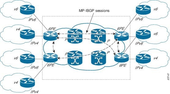
The following figure illustrates the 6PE topology.

V6

IPv6 router on the customer premises

6PE

PE equipment, connected to CEs and entry points to the MPLS clouds, running a dual stack IPv6/IPv4 (IPv6 to communicate with CEs)

V4

IPv4 router on the customer premises

P

Provider routers, core of the MPLS backbone running MPLS and IPv4 stack

IPv6 on VPN Provider Edge Routers

6VPE is a mechanism to use the IPv4 backbone to provide VPN IPv6 services. It takes advantage of operational IPv4 MPLS backbones, eliminating the need for dual-stacking within the MPLS core. This translates to savings in operational costs and addresses the security limitations of the 6PE approach. 6VPE is more like a regular IPv4 MPLS-VPN provider edge, with an addition of IPv6 support within VRF. It provides logically separate routing table entries for VPN member devices.

Components of MPLS-based 6VPE Network

  • VPN route target communities – A list of all other members of a VPN community.
  • Multiprotocol BGP (MP-BGP) peering of VPN community PE routers – Propagates VRF reachability information to all members of a VPN community.
  • MPLS forwarding – Transports all traffic between all VPN community members across a VPN service-provider network.

In the MPLS-VPN model a VPN is defined as a collection of sites sharing a common routing table. A customer site is connected to the service provider network by one or more interfaces, where the service provider associates each interface with a VPN routing table–known as the VRF table.

For more conceptual information on 6PE and 6VPE, see the IPv6 VPN over MPLS guide in the MPLS: Layer 3 VPNs Configuration Guide.

Supported Features

The following 6PE and 6VPE features are supported on the Cisco ASR 901 router effective with Cisco IOS Release 15.2(2) SNI:

  • IPv6 VRF support – Enabled for supporting 6VPE
  • MPLS VPN 6VPE and 6PE – Provides IPV6 reachability for IPv6 edge routers across an MPLS network backbone running an IPv4 control plane, without making changes to the software on the MPLS P routers.
  • 6VPE and 6PE with QoS – Supports QoS provisioning in 6PE and 6VPE networks by using existing QoS infrastructure and configuration.
  • MPLS VPN - VRF command for IPv4 and IPv6 VPN – Supports commands that allows users to enable IPv4 and IPv6 in the same VRF.

Note

All the above features are built upon existing IPv4, IPv6, MPLS and BGP infrastructure in the IOS and Cisco ASR 901 data plane support.

Scalability Numbers

Table 1 shows the scalability numbers for the 6PE and 6VPE feature.

Table 1. Scalability Numbers for 6PE and 6VPE

Interface

Numbers

Number of VRFs

113

Number of VPNv6 prefixes per VRF

About 4000 1

Number of VPNv6 prefixes

About 4000 Table 1

Number of global IPv6 prefixes

About 4000 Table 1

1 This number is limited by the MPLS label usage on the PE router. The maximum number of label space shared between IPv4 and IPv6 is 4000.

How to Configure IPv6 over MPLS: 6PE and 6VPE

This section describes how to configure IPv6 over MPLS: 6PE and 6VPE feature:

Configuring 6PE

Ensure that you configure 6PE on PE routers participating in both the IPv4 cloud and IPv6 clouds. To learn routes from both clouds, you can use any routing protocol supported on IOS (BGP, OSPF, IS-IS, EIGRP, Static).

BGP running on a PE router should establish (IPv4) neighborhood with BGP running on other PEs. Subsequently, it should advertise the IPv6 prefixes learnt from the IPv6 table to the neighbors. The IPv6 prefixes advertised by BGP would automatically have IPv4-encoded-IPv6 addresses as the nexthop-address in the advertisement.

To configure 6PE, complete the following steps:

Procedure

  Command or Action Purpose
Step 1

enable

Example:


Router> enable

Enables privileged EXEC mode.

  • Enter your password if prompted.
Step 2

configure terminal

Example:


Router# configure terminal

Enters global configuration mode.

Step 3

ip cef

Example:


Router(config)# ip cef

Enables Cisco Express Forwarding on the router.

Step 4

ipv6 cef

Example:


Router(config)# ipv6 cef 

Enables Cisco Express Forwarding for IPv6.

Step 5

ipv6 unicast-routing

Example:


Router(config)# ipv6 unicast-routing 

Enables the forwarding of IPv6 unicast datagrams.

Step 6

router bgp as-number

Example:


Router(config)# router bgp 100

Enters the number that identifies the autonomous system (AS) in which the router resides.

  • as-number —Autonomous system number. Range for 2-byte numbers is 1 to 65535. Range for 4-byte numbers is 1.0 to 65535.65535.
Step 7

no synchronization

Example:


Router(config-router)# no synchronization 

Advertises a network route without waiting for IGP.

Step 8

no bgp default ipv4-unicast

Example:


Router(config-router)# no bgp default 
ipv4-unicast 

Disables the default IPv4 unicast address family for peering session establishment.

Step 9

neighbor {ip-address | ipv6-address | peer-group-name} remote-as as-number

Example:


Router(config-router)# neighbor 10.108.1.2 
remote-as 65200

Adds an entry to the BGP or multiprotocol BGP neighbor table.

  • ip-address —IP address of a peer router with which routing information will be exchanged.
  • ipv6-address —IPv6 address of a peer router with which routing information will be exchanged.
  • peer-group-name —Name of the BGP peer group.
  • remote-as —Specifies a remote autonomous system.
  • as-number —Number of an autonomous system to which the neighbor belongs, ranging from 1 to 65535.
Step 10

neighbor {ip-address | ipv6-address | peer-group-name} update-source interface-type interface-number

Example:


Router(config-router)# neighbor 172.16.2.3 
update-source Loopback0

Configures BGP sessions to use any operational interface for TCP connections.

Step 11

address-family ipv6

Example:


Router(config-router)# address-family ipv6

Enters address family configuration mode for configuring routing sessions, such as BGP, that use standard IPv6 address prefixes.

Step 12

neighbor {ip-address | ipv6-address | peer-group-name} activate

Example:


Router(config-router-af)# neighbor 10.0.0.44 
activate

Enables the exchange of information with a BGP neighbor.

Step 13

neighbor {ip-address | ipv6-address | peer-group-name} send-label

Example:


Router(config-router-af)# neighbor 10.0.0.44 
send-label

Sends MPLS labels with BGP routes to a neighboring BGP router.

Step 14

exit-address-family

Example:


Router(config-router-af)# exit-address-family 

Exits BGP address-family submode.

Configuring 6VPE

6VPE requires setting up of IPv6 connectivity from PE to CE routers, MP-BGP peering to the neighboring PE and MPLS/IPv4 connectivity to the core network using supported routing protocols (like OSPF, IS-IS, EIGRP, Static) as done in 6PE. In addition, IPv6 VRFs have to be created on the PE routers and attached to the interfaces connecting to CE routers. IPv6-only or dual-stack(multi-protocol) VRFs support IPv6 VRF definitions.

To configure 6VPE, perform the tasks given below:

Setting up IPv6 Connectivity from PE to CE Routers

To configure IPv6 connectivity from PE to CE routers, complete the following steps:

Procedure
  Command or Action Purpose
Step 1

enable

Example:

Router> enable

Enables the privileged EXEC mode.

  • Enter your password if prompted.
Step 2

configure terminal

Example:

Router# configure terminal

Enters the global configuration mode.

Step 3

router bgp

Example:

Router(config)# router bgp 100

Enters the number that identifies the autonomous system (AS) in which the router resides. Autonomous system number: Range for 2-byte numbers is 1 to 65535. Range for 4-byte numbers is 1.0 to 65535.65535.

Step 4

address-family ipv6 [vrf vrf-name]

Example:

Router(config-router)# address-family ipv6 
labeled-unicast 

Enters address family configuration mode for configuring routing sessions, such as BGP, that use standard IPv6 address prefixes.

  • vrf —(Optional) Specifies all VRF instance tables or a specific VRF table for an IPv6 address.
  • vrf-name —(Optional) A specific VRF table for an IPv6 address.
Step 5

neighbor{ip-address | ipv6-address | peer-group-name} remote-as as-number

Example:

Router(config-router-af)# neighbor 10.108.1.2 
remote-as 65200

Adds an entry to the BGP or multiprotocol BGP neighbor table.

  • ip-address —IP address of a peer router with which routing information will be exchanged.
  • ipv6-address —IPv6 address of a peer router with which routing information will be exchanged.
  • peer-group-name —Name of the BGP peer group.
  • remote-as —Specifies a remote autonomous system.
  • as-number —Number of an autonomous system to which the neighbor belongs, ranging from 1 to 65535.
Step 6

neighbor{ip-address | ipv6-address | peer-group-name} activate

Example:

Router(config-router-af)# neighbor 10.0.0.44 
activate

Enables the exchange of information with a BGP neighbor.

Step 7

exit-address-family

Example:

Router(config-router-af)# exit-address-family 

Exits the BGP address-family submode.

Setting up MP-BGP Peering to the Neighboring PE

To configure MP-BGP peering to the neighboring PE routers, complete the following steps:

Procedure
  Command or Action Purpose
Step 1

enable

Example:

Router> enable

Enables the privileged EXEC mode.

  • Enter your password if prompted.
Step 2

configure terminal

Example:

Router# configure terminal

Enters the global configuration mode.

Step 3

router bgp as-number

Example:

Router(config)# router bgp 100

Enters the number that identifies the autonomous system (AS) in which the router resides. Autonomous system number. Range for 2-byte numbers is 1 to 65535. Range for 4-byte numbers is 1.0 to 65535.65535.

Step 4

address-family vpnv6

Example:

Router(config-router)# address-family vpnv6 

Places the router in address family configuration mode for configuring routing sessions, such as BGP, that use standard VPNv6 address prefixes.

Step 5

neighbor {ip-address | ipv6-address | peer-group-name} activate

Example:

Router(config-router-af)# neighbor 10.0.0.44 
activate

Enable the exchange of information with a BGP neighbor.

Step 6

neighbor {ip-address | ipv6-address | peer-group-name} send-community extended

Example:

Router(config-router-af)# neighbor 10.108.1.2 
send-community extended

Adds an entry to the BGP or multiprotocol BGP neighbor table.

Step 7

exit-address-family

Example:

Router(config-router-af)# exit-address-family 

Exits the BGP address-family submode.

Setting up MPLS/IPv4 Connectivity with LDP

To configure MPLS and IPv4 connectivity with LDP, complete the following steps:

Procedure
  Command or Action Purpose
Step 1

enable

Example:

Router> enable

Enables the privileged EXEC mode.

  • Enter your password if prompted.
Step 2

configure terminal

Example:

Router# configure terminal

Enters the global configuration mode.

Step 3

interface ip-address

Example:

Router(config)# interface vlan 100

Configures an interface type and to enter interface configuration mode.

  • interface-name—Interface name.
Step 4

ip address ip-address

Example:

Router(config-if)# ip address 1.1.1.1 255.255.255.0

Sets a primary or secondary IP address for an interface.

Step 5

mpls ip

Example:

Router(config-if)# mpls ip 

Enables MPLS forwarding of IP packets along normally routed paths for a particular interface.

Step 6

exit

Example:

Router(config-if)# exit 

Exits the interface configuration mode.

Creating IPv6 VRFs on PE Routers

To configure IPv6 VRFs on the PE routers, complete the following tasks:

Configuring IPv6-only VRF

To configure IPv6-only VRF, complete the following steps:

Procedure
  Command or Action Purpose
Step 1

enable

Example:

Router> enable

Enables privileged EXEC mode.

  • Enter your password if prompted.
Step 2

configure terminal

Example:

Router# configure terminal

Enters global configuration mode.

Step 3

vrf definition vrf-name

Example:

Router(config)# vrf definition red

Configures a VRF routing table instance and enters VRF configuration mode.

  • vrf-name—Name assigned to a VRF.
Step 4

address-family ipv6

Example:

Router(config-vrf)# address-family ipv6 

Enters address family configuration mode for configuring routing sessions that use standard IPv6 address prefixes.

Step 5

exit-address-family

Example:

Router(config-vrf-af)# exit-address-family

Exits address-family submode.

Configuring Dual-stack VRF

To configure dual-stack VRF, complete the following steps:

Procedure
  Command or Action Purpose
Step 1

enable

Example:

Router> enable

Enables privileged EXEC mode.

  • Enter your password if prompted.
Step 2

configure terminal

Example:

Router# configure terminal

Enters global configuration mode.

Step 3

vrf definition vrf-name

Example:

Router(config)# vrf definition red

Configures a VRF routing table instance and enters VRF configuration mode.

  • vrf-name—Name assigned to a VRF.
Step 4

address-family ipv4

Example:

Router(config-vrf)# address-family ipv4 

Enters address family configuration mode for configuring routing sessions that use standard IPv4 address prefixes.

Step 5

exit-address-family

Example:

Router(config-vrf-af)# exit-address-family

Exits address-family submode.

Step 6

address-family ipv6

Example:

Router(config-vrf)# address-family ipv6 

Enters address family configuration mode for configuring routing sessions that use standard IPv6 address prefixes.

Step 7

exit-address-family

Example:

Router(config-vrf-af)# exit-address-family

Exits address-family submode.

Verifying IPv6 over MPLS: 6PE and 6VPE Configuration

To verify the IPv6 over MPLS: 6PE and 6VPE configuration, use the show commands shown in the following examples.

To display BGP entries from all of the customer-specific IPv6 routing tables, use the following show command.


Router# show bgp vpnv6 unicast all

Network                   Next Hop              Metric LocPrf    Weight Path
Route Distinguisher: 100:1
*  2001:100:1:1000::/56   2001:100:1:1000::72a    0               0     200 ?
*                         ::                0                      32768 ?
*  i2001:100:1:2000::/56  ::FFFF:200.10.10.1
Route Distinguisher: 200:1
*  2001:100:2:1000::/56   ::               0                       32768 ?
*  2001:100:2:2000::/56   ::FFFF:200.10.10.1      0                 32768 ?

To display the parameters and the current state of the active IPv6 routing protocol processes, use the following show command:


Router# show ipv6 protocols vrf vpe_1

IPv6 Routing Protocol is "connected"
IPv6 Routing Protocol is "bgp 100"
  IGP synchronization is disabled
  Redistribution:
    None
  Neighbor(s):
    Address                    FiltIn FiltOut Weight RoutemapIn RoutemapOut
    100::2

To display IPv6 router advertisement (RA) information received from on-link devices, use the following show command:


Router# show ipv6 route vrf vpe_1

IPv6 Routing Table - vpe_1 - 29 entries
Codes: C - Connected, L - Local, S - Static, U - Per-user Static route
       B - BGP, R - RIP, H - NHRP, I1 - ISIS L1
       I2 - ISIS L2, IA - ISIS interarea, IS - ISIS summary, D - EIGRP
       EX - EIGRP external, ND - ND Default, NDp - ND Prefix, DCE - Destination
       NDr - Redirect
       O - OSPF Intra, OI - OSPF Inter, OE1 - OSPF ext 1, OE2 - OSPF ext 2
       ON1 - OSPF NSSA ext 1, ON2 - OSPF NSSA ext 2
B   72::/64 [20/0]
     via 100::2
B   72:0:0:1::/64 [20/0]
     via 100::2
B   72:0:0:2::/64 [20/0]
     via 100::2
B   72:0:0:4::/64 [20/0]
     via 100::2
B   72:0:0:5::/64 [20/0]
     via 100::2
B   72:0:0:6::/64 [20/0]
     via 100::2
B   72:0:0:7::/64 [20/0]
     via 100::2
B   72:0:0:8::/64 [20/0]
     via 100::2
B   72:0:0:9::/64 [20/0]
     via 100::2
B   72:0:0:A::/64 [20/0]
     via 100::2
B   72:0:0:B::/64 [20/0]
     via 100::2
B   72:0:0:C::/64 [20/0]
     via 100::2
B   72:0:0:D::/64 [20/0]
     via 100::2
B   72:0:0:E::/64 [20/0]
     via 100::2
B   72:0:0:F::/64 [20/0]
     via 100::2
B   72:0:0:10::/64 [20/0]
     via 100::2
B   72:0:0:11::/64 [20/0]
     via 100::2
B   72:0:0:12::/64 [20/0]
     via 100::2

To display the Cisco Express Forwarding Forwarding Information Base (FIB) associated with an IPv6 Virtual Private Network (VPN) routing and forwarding (VRF) instance, use the following show command.


Router# show ipv6 cef vrf cisco1

2001:8::/64 
  attached to GigabitEthernet0/0/1 
 2001:8::3/128 
  receive 
 2002:8::/64 
  nexthop 10.1.1.2 GigabitEthernet0/1/0 label 22 19 
 2010::/64 
  nexthop 2001:8::1 GigabitEthernet0/0/1 
 2012::/64 
  attached to Loopback1 
 2012::1/128 
  receive 

To display IPv6 routing table information associated with a VPN routing and forwarding (VRF) instance, use the following show command.


Router# show ipv6 route vrf

IPv6 Routing Table cisco1 - 6 entries
Codes: C - Connected, L - Local, S - Static, R - RIP, B - BGP 
       U - Per-user Static route 
       I1 - ISIS L1, I2 - ISIS L2, IA - ISIS interarea 
       O - OSPF intra, OI - OSPF inter, OE1 - OSPF ext 1, OE2 - OSPF ext 2 
C   2001:8::/64 [0/0] 
     via ::, GigabitEthernet0/0/1
L   2001:8::3/128 [0/0] 
     via ::, GigabitEthernet0/0/1 
B   2002:8::/64 [200/0] 
     via ::FFFF:192.168.1.4, 
B   2010::/64 [20/1] 
     via 2001:8::1, 
C   2012::/64 [0/0] 
     via ::, Loopback1 
L   2012::1/128 [0/0] 
     via ::, Loopback1

To display label forwarding information for advertised Virtual Private Network (VPN) routing and forwarding (VRF) instance routes, use the following show command.


Router# show mpls forwarding-table vrf vpe_1

Local      Outgoing   Prefix           Bytes Label   Outgoing   Next Hop
Label      Label      or Tunnel Id     Switched      interface
1760       No Label   72::/64[V]       0             Vl100      100::2
1761       No Label   72:0:0:1::/64[V] 0             Vl100      100::2
1762       No Label   72:0:0:2::/64[V] 0             Vl100      100::2
1764       No Label   72:0:0:3::/64[V] 0             Vl100      100::2
1765       No Label   72:0:0:4::/64[V] 0             Vl100      100::2
1768       No Label   72:0:0:7::/64[V] 0             Vl100      100::2
1769       No Label   72:0:0:8::/64[V] 0             Vl100      100::2
1770       No Label   72:0:0:9::/64[V] 0             Vl100      100::2
1771       No Label   72:0:0:A::/64[V] 0             Vl100      100::2
1772       No Label   72:0:0:B::/64[V] 0             Vl100      100::2
1773       No Label   72:0:0:C::/64[V] 0             Vl100      100::2
1774       No Label   72:0:0:D::/64[V] 0             Vl100      100::2
1775       No Label   72:0:0:E::/64[V] 0             Vl100      100::2
1776       No Label   72:0:0:F::/64[V] 0             Vl100      100::2
1777       No Label   72:0:0:10::/64[V]   \
                                       0             Vl100      100::2
1778       No Label   72:0:0:11::/64[V]   \
                                       0             Vl100      100::2
Local      Outgoing   Prefix           Bytes Label   Outgoing   Next Hop
Label      Label      or Tunnel Id     Switched      interface
1779       No Label   72:0:0:12::/64[V]   \
                                       0             Vl100      100::2
1780       No Label   72:0:0:13::/64[V]   \
                                       0             Vl100      100::2
1781       No Label   72:0:0:14::/64[V]   \
                                       0             Vl100      100::2
1782       No Label   72:0:0:15::/64[V]   \
                                       0             Vl100      100::2
1783       No Label   72:0:0:16::/64[V]   \
                                       0             Vl100      100::2
1784       No Label   72:0:0:17::/64[V]   \
                                       0             Vl100      100::2
1785       No Label   72:0:0:18::/64[V]   \
                                       0             Vl100      100::2

To display output information linking the MPLS label with prefixes, use the following show command.


Router# show mpls forwarding-table

Local Outgoing      Prefix            Bytes tag Outgoing       Next Hop       
tag   tag or VC     or Tunnel Id      switched  interface                     
16    Aggregate     IPv6              0             
17    Aggregate     IPv6              0                 
18    Aggregate     IPv6              0                 
19    Pop tag       192.168.99.64/30  0         GE0/0         point2point    
20    Pop tag       192.168.99.70/32  0         GE0/0         point2point      
21    Pop tag       192.168.99.200/32 0         GE0/0         point2point    
22    Aggregate     IPv6              5424    
23    Aggregate     IPv6              3576 
24    Aggregate     IPv6              2600

To display entries in the IPv6 BGP routing table, use the following show command:


Router# show bgp ipv6 2001:33::/64 

BGP routing table entry for 2001:33::/64, version 3
Paths: (1 available, best #1, table Global-IPv6-Table)
 Not advertised to any peer
 Local
 ::FFFF:192.168.0.2 (metric 30) from 192.168.0.2 (192.168.0.2)
 Origin IGP, localpref 100, valid, internal, best
Configuration Examples

This section provides sample configuration examples for IPv6 over MPLS: 6PE and 6VPE feature on the Cisco ASR 901 router.

Example: Configuring 6PE

The following is a sample configuration of 6PE.


interface GigabitEthernet0/3/0/0
 ipv6 address 2001::1/64
!
router isis ipv6-cloud
 net 49.0000.0000.0001.00
 address-family ipv6 unicast
  single-topology
 interface GigabitEthernet0/3/0/0
  address-family ipv6 unicast
  !
!
router bgp 55400
 bgp router-id 54.6.1.1
 address-family ipv4 unicast
 !
 address-family ipv6 unicast
  network 55:5::/64
  redistribute connected
  redistribute isis ipv6-cloud
   allocate-label all
 !
 neighbor 34.4.3.3
  remote-as 55400
  address-family ipv4 unicast
  !
  address-family ipv6 labeled-unicast

Example: Configuring 6VPE

The following is a sample configuration of 6VPE.


vrf vpn1
 address-family ipv6 unicast
  import route-target
   200:2
  !
  export route-target
   200:2
interface Loopback0
 ipv4 address 10.0.0.1 255.255.255.255
interface GigabitEthernet0/0/0/1                             
 vrf  vpn1
 ipv6 address 2001:c003:a::2/64 
router bgp 1
 bgp router-id 10.0.0.1
 bgp redistribute-internal
 bgp graceful-restart
 address-family ipv4 unicast
!
address-family vpnv6 unicast
 !
 neighbor 10.0.0.2                >>>> Remote peer loopback address.
  remote-as 1
  update-source Loopback0
  address-family ipv4 unicast
  !
  address-family vpnv6 unicast
   route-policy pass-all in 
   route-policy pass-all out
 !
  vrf vpn1
   rd 100:2
   bgp router-id 140.140.140.140
   address-family ipv6 unicast
   redistribute connected
 !
 neighbor 2001:c003:a::1
   remote-as 6502
   address-family ipv6 unicast
   route-policy pass-all in
   route-policy pass-all out

Additional References

The following sections provide references related to IPv6 over MPLS: 6PE and 6VPE feature.

Related Documents

Related Topic

Document Title

Cisco IOS Commands

Cisco IOS Master Commands List, All Releases

Cisco ASR 901 Command Reference

Cisco ASR 901 Series Aggregation Services Router Command Reference

IPv6 Provider Edge Router over MPLS

Cisco IOS IPv6 Provider Edge Router (6PE) over MPLS

IPv6 VPN over MPLS

MPLS: Layer 3 VPNs Configuration Guide

Standards

Standard

Title

None

MIBs

MIB

MIBs Link

None

To locate and download MIBs for selected platforms, Cisco IOS releases, and feature sets, use Cisco MIB Locator found at the following URL:

http://www.cisco.com/go/mibs

RFCs

RFC

Title

None

Technical Assistance

Description

Link

The Cisco Technical Support website contains thousands of pages of searchable technical content, including links to products, technologies, solutions, technical tips, and tools. Registered Cisco.com users can log in from this page to access even more content.

http://www.cisco.com/techsupport

Feature Information for IPv6 over MPLS: 6PE and 6VPE

Table 1 lists the features in this module and provides links to specific configuration information.

Use Cisco Feature Navigator to find information about platform support and software image support. Cisco Feature Navigator enables you to determine which software images support a specific software release, feature set, or platform. To access Cisco Feature Navigator, go to http://www.cisco.com/go/cfn . An account on Cisco.com is not required.


Note

Table 1 lists only the software release that introduced support for a given feature in a given software release train. Unless noted otherwise, subsequent releases of that software release train also support that feature.
Table 2. Feature Information for IPv6 over MPLS: 6PE and 6VPE

Feature Name

Releases

Feature Information

IPv6 over MPLS: 6PE and 6VPE

15.2(2)SNI

This feature was introduced on the Cisco ASR 901 routers.

The following sections provide information about this feature: