Configuring MST on EVC Bridge Domain

This section describes how to configure MST on EVC Bridge Domain.

Overview of MST and STP

Spanning Tree Protocol (STP) is a Layer 2 link-management protocol that provides path redundancy while preventing undesirable loops in the network. For a Layer 2 Ethernet network to function properly, only one active path can exist between any two stations. STP operation is transparent to end stations, which cannot detect whether they are connected to a single LAN segment or a switched LAN of multiple segments.

MST maps multiple VLANs into a spanning tree instance, with each instance having a spanning tree topology independent of other spanning tree instances. This architecture provides multiple forwarding paths for data traffic, enables load balancing, and reduces the number of spanning tree instances required to support a large number of VLANs. MST improves the fault tolerance of the network because a failure in one instance (forwarding path) does not affect other instances (forwarding paths).

For routers to participate in MST instances, you must consistently configure the routers with the same MST configuration information. A collection of interconnected routers that have the same MST configuration comprises an MST region. For two or more routers to be in the same MST region, they must have the same VLAN-to-instance mapping, the same configuration revision number, and the same MST name.

The MST configuration controls the MST region to which each router belongs. The configuration includes the name of the region, the revision number, and the MST VLAN-to-instance assignment map.

A region can have one or multiple members with the same MST configuration; each member must be capable of processing RSTP bridge protocol data units (BPDUs). There is no limit to the number of MST regions in a network, but each region can support up to 65 spanning tree instances. Instances can be identified by any number in the range from 0 to 4094. You can assign a VLAN to only one spanning tree instance at a time.

Overview of MST on EVC Bridge Domain

The MST on EVC Bridge-Domain feature uses VLAN IDs for service-instance-to-MST-instance mapping. EVC service instances with the same VLAN ID (the outer VLAN IDs in the QinQ case) as the one in another MST instance will be mapped to that MST instance.

EVC service instances can have encapsulations with a single tag as well as double tags. In case of double tag encapsulations, the outer VLAN ID shall be used for the MST instance mapping, and the inner VLAN ID is ignored.

A single VLAN per EVC is needed for the mapping with the MST instance. The following service instances without any VLAN ID or with multiple outer VLAN IDs are not supported:

  • Untagged (encapsulation untagged) is supported but there is no loop detection on the EVC
  • Priority-tagged (encapsulation priority-tagged)
  • Multiple outer tags (encapsulation dot1q 200 to 400 second-dot1q 300)

Restrictions and Guidelines

The following restrictions and guidelines apply to MST on EVC bridge domain:

  • Cisco IOS Release 15.1(2)SNG supports EVC port-channels.
  • With default configuration, Cisco ASR 901 does not run any spanning-tree protocol. Hence all the ports participating in bridge domains are moved to forward state. To enable MSTP, issue spanning-tree mode mstp command in the global configuration mode.
  • Main interface where the EFP is configured must be up and running with MSTP as the selected Spanning Tree Mode (PVST and Rapid-PVST are not supported).
  • The SPT PortFast feature is not supported with EFPs.
  • The co-existence of REP and mLACP with MST on the same port is not supported.
  • Any action performed on VPORT (which represents a particular VLAN in a physical port) affects the bridge domain and other services.
  • Supports 32 MSTs and one CIST (common and internal spanning tree).
  • Supports one MST region.
  • Scales to 4000 EFPs.
  • Untagged EVCs do not participate in MST loop detection.
  • Service instances without any VLAN ID in the encapsulation are not supported, because a unique VLAN ID is required to map an EVC to an MST instance.
  • Supports EFPs with unambiguous outer VLAN tag (that is, no range, list on outer VLAN, neither default nor untagged).
  • Removing dot1q encapsulation removes the EVC from MST.
  • Changing the VLAN (outer encapsulation VLAN of EVC) mapping to a different MST instance will move the EVC port to the new MST instance.
  • Changing an EVC service instance to a VLAN that has not been defined in MST 1 will result in mapping of EVC port to MST 0.
  • The peer router of the EVC port must also be running MST.
  • MST is supported only on EVC BD. EVCs without BD configuration will not participate in MST.
  • When an MST is configured on the outer VLAN, you can configure any number of service instances with the same outer VLAN as shown in the following configuration example.

nPE1#sh run int gi0/5
Building configuration...
Current configuration : 373 bytes
!
interface GigabitEthernet0/5
 description connected to CE1
 no ip address
 service instance 100 ethernet
  encapsulation dot1q 100 second-dot1q 1
  bridge-domain 100
 !
 service instance 101 ethernet
  encapsulation dot1q 100 second-dot1q 2
  bridge-domain 101
 !
 service instance 102 ethernet
  encapsulation dot1q 100 second-dot1q 120-140
  bridge-domain 102
 !
end
nPE1#sh run int gi0/6
Building configuration...
Current configuration : 373 bytes
!
interface GigabitEthernet0/6
 description connected to CE1
 no ip address
 service instance 100 ethernet
  encapsulation dot1q 100 second-dot1q 1
  bridge-domain 100
 !
 service instance 101 ethernet
  encapsulation dot1q 100 second-dot1q 2
  bridge-domain 101
 !
 service instance 102 ethernet
  encapsulation dot1q 100 second-dot1q 120-140
  bridge-domain 102
 !
end
nPE1#sh span vlan 100
MST0
  Spanning tree enabled protocol mstp
  Root ID    Priority    32768
             Address     0018.742f.3b80
             Cost        0
             Port        2821 (GigabitEthernet12/5)
             Hello Time   2 sec  Max Age 20 sec  Forward Delay 15 sec
  Bridge ID  Priority    32768  (priority 32768 sys-id-ext 0)
             Address     001a.303c.3400
             Hello Time   2 sec  Max Age 20 sec  Forward Delay 15 sec
Interface           Role Sts Cost      Prio.Nbr Type
------------------- ---- --- --------- -------- --------------------------------
Gi12/5              Root FWD 20000     128.2821 P2p 
Gi12/6              Altn BLK 20000     128.2822 P2p 
nPE1#

Configuring MST on EVC Bridge Domain

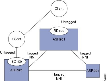
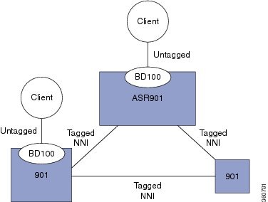
Untagged EVCs not participating in MST loop detection shows an example of the untagged EVCs that do not participate in MST loop detection. When you link your networks together as shown below, a loop is caused since MST is not running on the untagged EVCs.

Figure 1. Untagged EVCs not participating in MST loop detection
Figure 2. MST with untagged EVCs without loop

Complete the following steps to configure MST on EVC bridge domain.

Procedure

  Command or Action Purpose
Step 1

enable

Example:


Router# enable

Enables privileged EXEC mode.

  • Enter your password if prompted.
Step 2

configure terminal

Example:


Router# configure terminal

Enters global configuration mode.

Step 3

interface gigabitethernet slot/port

Example:


Router(config)# interface gigabitethernet 0/1

Specifies the gigabit ethernet interface to configure.

  • slot/port —Specifies the location of the interface.
Step 4

[no] service instance id Ethernet [service-name]

Example:


Router(config-if)# service instance 101 ethernet

Creates a service instance (EVC instance) on an interface and sets the device into the config-if-srv submode.

Step 5

encapsulation dot1q vlan-id

Example:


Router(config-if-srv)# encapsulation dot1q 13

Defines the matching criteria to be used in order to map ingress dot1q frames on an interface to the appropriate service instance.

Step 6

[no] bridge-domain bridge-id

Example:


Router(config-if-srv)# bridge-domain 12

Binds the service instance to a bridge domain instance where bridge-id is the identifier for the bridge domain instance.

Configuration Example for MST on EVC Bridge Domain

In the following example, two interfaces participate in MST instance 0, the default instance to which all VLANs are mapped:


Router# enable
Router# configure terminal
Router(config)# interface g0/1
Router(config-if)# service instance 1 ethernet
Router(config-if-srv)# encapsulation dot1q 2
Router(config-if-srv)# bridge-domain 100
Router(config-if-srv)# interface g0/3
Router(config-if)# service instance 1 ethernet
Router(config-if-srv)# encapsulation dot1q 2
Router(config-if-srv)# bridge-domain 100
Router(config-if-srv)# end

Verification

Use this command to verify the configuration:


Router# show spanning-tree vlan 2 
MST0
  Spanning tree enabled protocol mstp
  Root ID    Priority    32768
             Address     0009.e91a.bc40
             This bridge is the root
             Hello Time   2 sec  Max Age 20 sec  Forward Delay 15 sec
  Bridge ID  Priority    32768  (priority 32768 sys-id-ext 0)
             Address     0009.e91a.bc40
             Hello Time   2 sec  Max Age 20 sec  Forward Delay 15 sec
Interface           Role Sts Cost      Prio.Nbr Type
------------------- ---- --- --------- -------- --------------------------------
Gi4/1 		 			Desg FWD 20000     128.1537 P2p 
Gi4/3             		 Back BLK 20000     128.1540 P2p 

In this example, interface gi4/1 and interface gi4/3 are connected back-to-back. Each has a service instance (EFP) attached to it. The EFP on both interfaces has an encapsulation VLAN ID of 2. Changing the VLAN ID from 2 to 8 in the encapsulation directive for the EFP on interface gi4/1 stops the MSTP from running in the MST instance to which the old VLAN is mapped and starts the MSTP in the MST instance to which the new VLAN is mapped:


Router(config-if)# interface  g4/1
Router(config-if)# service instance 1 ethernet
Router(config-if-srv)# encap dot1q 8
Router(config-if-srv)# end

Use this command to verify the configuration:


Router# show spanning-tree vlan 2
MST1
  Spanning tree enabled protocol mstp
  Root ID    Priority    32769
             Address     0009.e91a.bc40
             This bridge is the root
             Hello Time   2 sec  Max Age 20 sec  Forward Delay 15 sec
  Bridge ID  Priority    32769  (priority 32768 sys-id-ext 1)
             Address     0009.e91a.bc40
             Hello Time   2 sec  Max Age 20 sec  Forward Delay 15 sec
Interface           Role Sts Cost      Prio.Nbr Type
------------------- ---- --- --------- -------- --------------------------------
Gi4/3             Desg FWD 20000     128.1540 P2p 
Router# show spanning-tree vlan 8
MST2
  Spanning tree enabled protocol mstp
  Root ID    Priority    32770
             Address     0009.e91a.bc40
             This bridge is the root
             Hello Time   2 sec  Max Age 20 sec  Forward Delay 15 sec
  Bridge ID  Priority    32770  (priority 32768 sys-id-ext 2)
             Address     0009.e91a.bc40
             Hello Time   2 sec  Max Age 20 sec  Forward Delay 15 sec
Interface           Role Sts Cost      Prio.Nbr Type
------------------- ---- --- --------- -------- --------------------------------
Gi4/1 					Desg FWD 20000     128.1537 P2p

In this example, interface gi4/3 (with an EFP that has an outer encapsulation VLAN ID of 2 and a bridge domain of 100) receives a new service:


Router# enable
Router# configure terminal
Router(config)# interface g4/3
Router((config-if)# service instance 2 ethernet
Router((config-if-srv)# encap dot1q 2 second-dot1q 100
Router((config-if-srv)# bridge-domain 200

Now there are two EFPs configured on interface gi4/3 and both of them have the same outer VLAN 2.


interface GigabitEthernet4/3
	 no ip address
	service instance 1 ethernet
	encapsulation dot1q 2
	bridge-domain 100
 !
 service instance 2 ethernet
  encapsulation dot1q 2 second-dot1q 100
   bridge-domain 200

The preceding configuration does not affect the MSTP operation on the interface; there is no state change for interface gi4/3 in the MST instance it belongs to.


Router# show spanning-tree mst 1  
##### MST1    vlans mapped:   2
Bridge        address 0009.e91a.bc40  priority      32769 (32768 sysid 1)
Root          this switch for MST1
Interface        Role Sts Cost      Prio.Nbr Type
---------------- ---- --- --------- -------- --------------------------------
Gi4/3          Desg FWD 20000     128.1540 P2p

This example shows MST on port channels:


Router# show spanning-tree mst 1
##### MST1 vlans mapped: 3
Bridge address 000a.f331.8e80 priority 32769 (32768 sysid 1)
Root address 0001.6441.68c0 priority 32769 (32768 sysid 1)
port Po5 cost 20000 rem hops 18
Interface Role Sts Cost Prio.Nbr Type
---------------- ---- --- --------- -------- --------------------------------
Gi2/0/0 Desg FWD 20000 128.257 P2p 
Po5 Root FWD 10000 128.3329 P2p 
Po6 Altn BLK 10000 128.3330 P2p 
Router# show spanning-tree vlan 3

MST1
Spanning tree enabled protocol mstp
Root ID Priority 32769
Address 0001.6441.68c0
Cost 20000
Port 3329 (Port-channel5)
Hello Time 2 sec Max Age 20 sec Forward Delay 15 sec
Bridge ID Priority 32769 (priority 32768 sys-id-ext 1)
Address 000a.f331.8e80
Hello Time 2 sec Max Age 20 sec Forward Delay 15 sec
Interface Role Sts Cost Prio.Nbr Type
------------------- ---- --- --------- -------- --------------------------------
Gi2/0/0 Desg FWD 20000 128.257 P2p 
Po5 Root FWD 10000 128.3329 P2p 
Po6 Altn BLK 10000 128.3330 P2p 
Troubleshooting Tips

Table 1. Troubleshooting Scenarios

Problem

Solution

Multiple Spanning Tree Protocol (MSTP) incorrectly or inconsistently formed due to misconfiguration and BPDU loss

To avoid BPDU loss, re-configure these on the following nodes:

  • Configuration name
  • Bridge revision
  • Provider-bridge mode
  • Instance to VLAN mapping

Determine if node A is sending BPDUs to node B. Use the show spanning-tree mst interface gi1/1 service instance command for each interface connecting the nodes. Only designated ports relay periodic BPDUs.

MSTP correctly formed, but traffic flooding occurs

Intermittent BPDU loss occurs when the spanning tree appears incorrectly in the show commands, but relays topology change notifications. These notifications cause a MAC flush, forcing traffic to flood until the MAC addresses are re-learned. Use the debug spanning-tree mst packet full {received | sent} command to debug topology change notifications.

Use the debug spanning-tree mst packet brief {received | sent } command on both nodes to check for missing BPDUs. Monitor the timestamps. A time gap greater than or equal to six seconds causes topology change.

MSTP shows incorrect port state

When the spanning tree protocol (STP) attempts to change the port state, it uses L2VPN. Check the value of the sent update. If the value is Yes, then STP is awaiting an update from L2VPN.

Packet forwarding does not match the MSTP state

Complete the following steps to verify and troubleshoot:

  1. Shut down redundant links, remove MSTP configuration, and ensure that basic bridging works.
  2. Check the state of each port as calculated by MSTP, and compare it with the packet counts transmitted and received on ports and EFPs controlled by MSTP. Normal data packets should be sent/received only on ports in the forwarding (FWD) state. BPDUs should be sent/received on all ports controlled by MSTP.
  3. Ensure that BPDUs are flowing and that root bridge selection is correct and check the related scenarios.
  4. Use the show l2vpn bridge-domain detail command to confirm the status of the members of the bridge domain. Ensure that the relevant bridge domain members are active.
  5. Check the forwarding state as programmed in hardware.