- Cisco ASR 901 Router Overview
- Licensing
- First-Time Configuration
- Managing and Monitoring Network Management Features
- Using the Command-Line Interface
- Software Upgrade
- Configuring Gigabit Ethernet Interfaces
- Configuring EtherChannels
- Configuring Ethernet OAM
- ITU-T Y.1731 Performance Monitoring
- Configuring Resilient Ethernet Protocol
- Configuring MST on EVC Bridge Domain
- Multiprotocol Label Switching
- Configuring EoMPLS
- Configuring MPLS VPNs
- Configuring MPLS OAM
- Configuring Routing Protocols
- Configuring Bidirectional Forwarding Detection
- Configuring T1/E1 Controllers
- Configuring Pseudowire
- Configuring Clocking
- G.8275.1 Telecom Profile
- Cisco IOS IP SLA
- Configuring QoS
- Configuring MLPPP
- Onboard Failure Logging
- Hot Standby Router Protocol and Virtual Router Redundancy Protocol
- Configuring Link Layer Discovery Protocol
- Configuring Multihop Bidirectional Forwarding Detection
- Bit Error Rate Testing
- Microwave ACM Signaling and EEM Integration
- IPv6 Support on the Cisco ASR 901 Router
- Labeled BGP Support
- BGP Support for Next-Hop Address Tracking
- MPLS Traffic Engineering - Fast Reroute Link Protection
- Layer 2 Control Protocol Peering, Forwarding, and Tunneling
- Configuring Inverse Muliplexing over ATM
- IPv6 over MPLS: 6PE and 6VPE
- Storm Control
- Remote Loop-Free Alternate - Fast Reroute
- Digital Optical Monitoring
- IPv4 Multicast
- IPv6 Multicast
- Configuring Switched Port Analyzer
- IP Security
- BCP Support on MLPPP
- ITU-T G.8032 Ethernet Ring Protection Switching
- Configuring NAT for IP Address Conservation
- Auto-IP
- IPv6 Routing: OSPFv3 Authentication Support with IPsec
- Policy-Based Routing
- Generic Routing Encapsulation
- Call Home
- PTP Debugging over GRE Tunnel
- Overview
- MAC Layer 2 Access Control Lists
- Index
- Finding Feature Information
- Prerequisites for Configuring ITU-T G.8032 Ethernet Ring Protection Switching
- Restrictions for Configuring ITU-T G.8032 Ethernet Ring Protection Switching
- Information About Configuring ITU-T G.8032 Ethernet Ring Protection Switching
- G.8032 Overview
- ITU-T G.8032 Ethernet Ring Protection Switching Functionality
- Single-Ring Topology
- Multiple-Rings Topology
- R-APS Control Messages
- CFM Protocols and Link Failures
- G.8032 Ring-Supported Commands and Functionality
- G.8032 ERP Timers
- Protection Switching Functionality in a Single Link Failure and Recovery
- How to Configure ITU-T G.8032 Ethernet Ring Protection Switching
- Configuration Examples for ITU-T G.8032 Ethernet Ring Protection Switching
- Additional References
- Feature Information for Configuring ITU-T G.8032 Ethernet Ring Protection Switching
ITU-T G.8032
Ethernet Ring Protection Switching
The ITU-T G.8032 Ethernet Ring Protection Switching feature implements protection switching mechanisms for Ethernet layer ring topologies. This feature uses the G.8032 Ethernet Ring Protection (ERP) protocol, defined in ITU-T G.8032, to provide protection for Ethernet traffic in a ring topology, while ensuring that no loops are within the ring at the Ethernet layer. The loops are prevented by blocking traffic on either a predetermined link or a failed link.
Effective from Cisco IOS Release 15.4 (3) S, the Cisco ASR 901 Router supports G.8032 on port-channel interface.
This chapter provides information about the following topics:
- Finding Feature Information
- Prerequisites for Configuring ITU-T G.8032 Ethernet Ring Protection Switching
- Restrictions for Configuring ITU-T G.8032 Ethernet Ring Protection Switching
- Information About Configuring ITU-T G.8032 Ethernet Ring Protection Switching
- How to Configure ITU-T G.8032 Ethernet Ring Protection Switching
- Configuration Examples for ITU-T G.8032 Ethernet Ring Protection Switching
- Additional References
- Feature Information for Configuring ITU-T G.8032 Ethernet Ring Protection Switching
Finding Feature Information
Your software release may not support all the features documented in this module. For the latest feature information and caveats, see the release notes for your platform and software release. To find information about the features documented in this module, and to see a list of the releases in which each feature is supported, see the “Feature Information for ITU-T G.8032 Ethernet Ring Protection Switching” section.
Use Cisco Feature Navigator to find information about platform support and Cisco software image support. To access Cisco Feature Navigator, go to http://www.cisco.com/go/cfn. An account on Cisco.com is not required.
Prerequisites for Configuring ITU-T G.8032 Ethernet Ring Protection Switching
Restrictions for Configuring ITU-T G.8032 Ethernet Ring Protection Switching
-
G.8032 is supported only on EFP bridgedomains on the physical interface and port-channel interface.
-
G.8032 is supported only on EFP with dot1q, dot1ad, QinQ, or dot1ad-dot1Q encapsulation type.
-
G.8032 is not supported on xconnect interface.
-
G.8032 does not support more than two ERP instances per ring.
-
CFM hardware offloading is supported on the Cisco ASR 901 Router only from Cisco IOS Release 15.4(3)S.
-
Link flap occurs while configuring the inclusion or exclusion VLAN list.
-
Admin shut down is highly recommended before making any changes in Connectivity Fault Management (CFM) configuration.
-
The efd notify command must be used under CFM configuration to notify G.8032 of failures, if any.
Information About Configuring ITU-T G.8032 Ethernet Ring Protection Switching
The following features are supported on the Cisco ASR 901 Routers from Cisco IOS Release 15.4(2)S onwards.
- G.8032 Overview
- ITU-T G.8032 Ethernet Ring Protection Switching Functionality
- Single-Ring Topology
- Multiple-Rings Topology
- R-APS Control Messages
- CFM Protocols and Link Failures
- G.8032 Ring-Supported Commands and Functionality
- G.8032 ERP Timers
- Protection Switching Functionality in a Single Link Failure and Recovery
G.8032 Overview
The G.8032 provides protection switching mechanisms, and a protocol for Ethernet layer network (ETH) rings. Ethernet rings provide wide-area multipoint connectivity more economically due to their reduced number of links. The mechanisms and protocol provide reliable and stable protection; and prevents loop formation, which could fatally affect network operation and service availability.
You can prevent loops in an Ethernet ring by ensuring that, at any moment, traffic can flow on all but one of the ring links, the Ring Protection Link (RPL), where the link is blocked in the working state. When the system detects a link failure, a Ring Automatic Protection Switching (RAPS) Signal Failure message is multicast to all the nodes, and the failed links end-point ports are blocked. When the RPL owner receives the message, it unblocks the RPL link. This triggers protection switching and a new traffic pattern is established on the ring. The blocked ports are then moved to the nodes next to the failed ones.
Effective from Cisco IOS Release 15.4(3)S, the Cisco ASR 901 Router supports G.8032 on port-channel interface and CFM hardware offloading.
-
Sub-second switching
-
EFP bridge domain over physical and port-channel interfaces
-
Up to six rings per node
-
Up to two ERP instances per ring
-
Open-ring and closed-ring support
-
Open-ring without virtual channel
-
G.8032-REP TCN interworking (TCN propagation)
-
G.8032-G.8032 TCN interworking—TCN propagation from subring to major ring
-
Minimum supported convergence time is 200 ms for a single instance, and 400 ms for multiple instances.
-
Effective from Cisco IOS Release 15.4 (3) S, the Cisco ASR 901 Router supports CFM hardware offloading with CCM interval 100ms, 10ms, and 3.3ms.
-
Minimum supported convergence time is 100 ms for a single instance, and 200 ms for multiple instances.
ITU-T G.8032 Ethernet Ring Protection Switching Functionality
The Ethernet ring protection functionality includes the following:
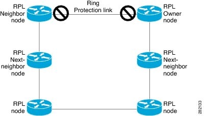
Loop avoidance in an Ethernet ring is achieved by ensuring that, at any time, traffic flows on all but the Ring Protection Link (RPL).
-
RPL owner—Responsible for blocking traffic over the RPL so that no loops are formed in the Ethernet traffic. There can be only one RPL owner in a ring.
-
RPL neighbor node—An Ethernet ring node adjacent to the RPL. It is responsible for blocking its end of the RPL under normal conditions. This node type is optional and prevents RPL usage when protected.
-
RPL next-neighbor node—Next-neighbor node is an Ethernet ring node adjacent to an RPL owner node or RPL neighbor node. It is mainly used for FDB flush optimization on the ring. This node is also optional.
The following figure illustrates the G.8032 Ethernet ring topology.
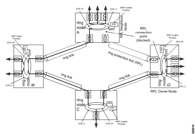
Single-Ring Topology
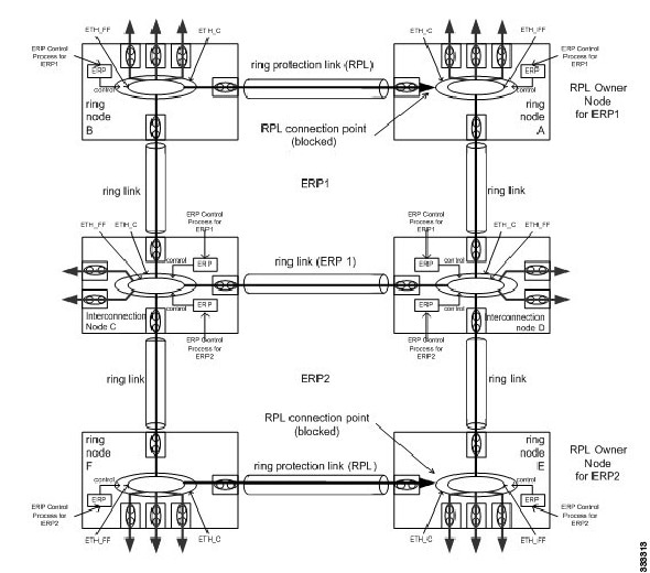
Multiple-Rings Topology
R-APS Control Messages
 Note | A single link failure in the ring ensures a loop-free topology. |
CFM Protocols and Link Failures
Connectivity Fault Management (CFM) and link status messages are used to detect ring link failure and node failure. During the recovery phase, when the failed link is restored, the nodes adjacent to the restored link send RAPS No Request (RAPS-NR) messages. On obtaining this message, the RPL owner blocks the RPL port and sends a RAPS-NR or RAPS Root Blocked (RAPS-RB) message. These messages cause all other nodes, except the RPL owner in the ring, to unblock all the blocked ports. The Ethernet Ring Protection (ERP) protocol works for both unidirectional failure and multiple link failure scenarios in a ring topology.
Note | The G.8032 ERP protocol uses CFM Continuity Check Messages (CCMs) at an interval of 1 second. At this interval (which is supported only on selected platforms), SONET-like switching time performance and loop-free traffic can be achieved. |
Note | The G.8032 ERP protocol uses CFM Continuity Check Messages (CCMs) at an interval of 3.3 ms. At this interval (which is supported only on selected platforms), SONET-like switching time performance and loop-free traffic can be achieved. |
Note | For G.8032 with Connectivity Fault Management (CFM) hardware offload, the CFM VLANs must be included in the exclusion VLANs list to avoid the down state of G.8032 rings. |
G.8032 Ring-Supported Commands and Functionality
A G.8032 ring supports these basic operator administrative commands:
-
Force switch (FS)—Allows the operator to forcefully block a particular ring port. Note the following points about FS commands: -
Manual switch (MS)—Allows the operator to manually block a particular ring port. Note the following points about MS commands: -
Clear—Cancels an existing FS or MS command on the ring port. The Clear command is used at the ring protection link (RPL) owner to clear a nonrevertive mode condition.
A G.8032 ring can support multiple instances. An instance is a logical ring running over a physical ring. Such instances are used for various reasons, such as load-balancing VLANs over a ring. For example, odd-numbered VLANs may go in one direction of the ring, and even-numbered VLANs may go in the other direction. Specific VLANs can be configured under only one instance. They cannot overlap multiple instances. Otherwise, data traffic or Ring Automatic Protection Switching (R-APS) messages may cross logical rings, which is not desirable.
G.8032 ERP Timers
The G.8032 Ethernet Ring Protection (ERP) protocol specifies the use of different timers to avoid race conditions and unnecessary switching operations:
-
Delay timers—Used by the Ring Protection Link (RPL) owner to verify that the network has stabilized before blocking the RPL. Note the following points about delay timers. -
After a signal failure (SF) condition, a Wait-to-Restore (WTR) timer is used to verify that the SF is not intermittent.
-
The WTR timer can be configured by the operator. The default time interval is 5 minutes; the time interval ranges from 1 to 12 minutes.
-
After a force switch (FS) or a manual switch (MS) command is issued, a Wait-to-Block (WTB) timer is used to verify that no background condition exists.
Note
The WTB timer interval may be shorter than the WTR timer interval.
-
-
Guard timer—Used by all nodes when changing state; the guard timer blocks latent outdated messages from causing unnecessary state changes. The guard timer can be configured. The default time interval is 500 ms; the time interval ranges from 10 to 2000 ms.
-
Hold-off timers—Used by the underlying Ethernet layer to filter out intermittent link faults. The hold-off timer can be configured. The default time interval is 0 seconds; the time interval ranges from 0 to 10 seconds. Faults are reported to the ring protection mechanism only if this timer expires.
Protection Switching Functionality in a Single Link Failure and Recovery
The following figure illustrates protection switching functionality in a single-link failure.
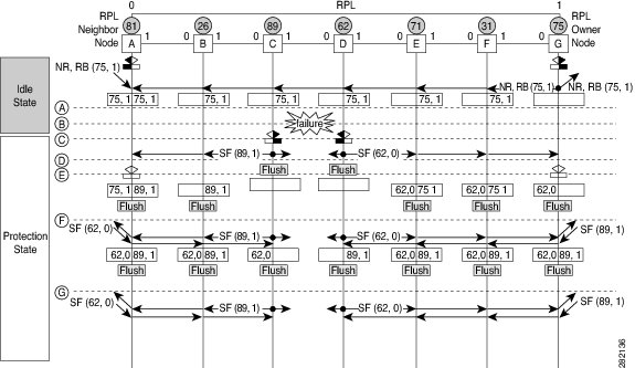
The following sequence describes the steps followed in the single-link failure:
-
A link operates in the normal condition.
-
A failure occurs.
-
Ethernet ring nodes C and D detect a local signal failure (SF) condition and after the hold-off time interval, block the failed ring port and perform the FDB flush.
-
Ethernet ring nodes C and D start sending Ring Automatic Protection Switching (R-APS) SF messages periodically along with the (node ID and bidirectional path-protected ring (BPR) identifier pair) on both ring ports while the SF condition persists.
-
All Ethernet ring nodes receiving an R-APS SF message perform the FDB flush. When the RPL owner node G and RPL neighbor node A receive an R-APS SF message, the Ethernet ring node unblocks its end of the RPL and performs the FDB flush.
-
All Ethernet ring nodes receiving a second R-APS SF message perform the FDB flush again; the additional FDB flush is because of the node ID and BPR-based configuration.
-
R-APS SF messages are detected on the Ethernet Ring indicating a stable SF condition. Further R-APS SF messages trigger no further action.
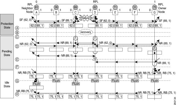
The following sequence describes the steps followed in the single-link failure revertive (recovery) operation:
-
A link operates in the stable SF condition.
-
Recovery of link failure occurs.
-
Ethernet ring nodes C and D detect clearing of the SF condition, start the guard timer, and initiate periodic transmission of the R-APS No Request (NR) messages on both ring ports. (The guard timer prevents the reception of R-APS messages.)
-
When the Ethernet ring nodes receive an R-APS NR message, the node ID and BPR identifier pair of a receiving ring port is deleted and the RPL owner node starts the Wait-to-Restore (WTR) timer.
-
When the guard timer expires on Ethernet ring nodes C and D, the nodes may accept the new R-APS messages, if any. Ethernet ring node D receives an R-APS NR message with a higher node ID from Ethernet ring node C, and unblocks its nonfailed ring port.
-
When the WTR timer expires, the RPL owner node blocks its end of the RPL, sends R-APS (NR or route blocked [RB]) message with the (node ID and BPR identifier pair), and performs the FDB flush.
-
When Ethernet ring node C receives an R-APS (NR or RB) message, the node removes the block on its blocked ring ports, and stops sending R-APS NR messages. On the other hand, when the RPL neighbor node A receives an R-APS NR or RB message, the node blocks its end of the RPL. In addition, Ethernet ring nodes A to F perform the FDB flush when receiving an RAPS NR or RB message because of the node ID and BPR-based configuration.
How to Configure ITU-T G.8032 Ethernet Ring Protection Switching
Configuring the Ethernet Ring Profile
To configure an Ethernet ring profile, complete the following steps.
Configuring an Ethernet Protection Ring
To configure an Ethernet Protection Ring (EPR), complete the following steps.
| Command or Action | Purpose | |||
|---|---|---|---|---|
| Step 1 | enable
Example: Router> enable |
Enables privileged EXEC mode. Enter your password if prompted. | ||
| Step 2 | configure
terminal
Example: Router# configure terminal |
Enters global configuration mode. | ||
| Step 3 | ethernet ring g8032
ring-name
Example: Router(config)# ethernet ring g8032 ring1 |
Creates the Ethernet ring and enters the Ethernet ring port configuration mode. | ||
| Step 4 | port0 interface
type
number
Example: Router(config-erp-ring)# port0 interface gigabitethernet 0/1 |
Connects port0 of the local node to the Ethernet ring and enters Ethernet ring protection mode. | ||
| Step 5 | monitor service instance
instance-id
Example: Router(config-erp-ring-port)# monitor service instance 1 |
(Optional) Assigns the Ethernet service instance to monitor the ring port (port0) and detect ring failures.
If this command is not used, G.8032 will track only the physical link failures. | ||
| Step 6 | exit
Example: Router(config-erp-ring-port)# exit |
Exits the Ethernet ring port configuration mode. | ||
| Step 7 | port1
{interface
type
number
|
none}
Example: Router(config-erp-ring)# port1 interface gigabitethernet 0/1 |
Connects port1 of the local node to the Ethernet ring and enters the Ethernet ring protection mode. | ||
| Step 8 | monitor service instance
instance-id
Example: Router(config-erp-ring-port)# monitor service instance 2 |
(Optional) Assigns the Ethernet service instance to monitor the ring port (port1) and detect ring failures.
If this command is not used, G.8032 will track only the physical link failures. | ||
| Step 9 | exit
Example: Router(config-erp-ring-port)# exit |
Exits Ethernet ring port configuration mode. | ||
| Step 10 | exclusion-list vlan-ids
vlan-id
Example: Router(config-erp-ring)# exclusion-list vlan-ids 2 |
(Optional) Specifies VLANs that are unprotected (unblocked) by the Ethernet ring protection mechanism. If the command is not used, VLANS that are not defined in the inclusion list in Step 16 will be completely blocked for the traffic. If the command is used, VLANS that are not defined in the inclusion list and exclusion list will be completely blocked for the traffic. | ||
| Step 11 | open-ring
Example: Router(config-erp-ring)# open-ring |
(Optional) Specifies the Ethernet ring as an open ring. By default, Ethernet ring is closed. | ||
| Step 12 | instance
instance-id
Example: Router(config-erp-ring)# instance 1 |
Configures the Ethernet ring instance and enters the Ethernet ring instance configuration mode. | ||
| Step 13 | description
descriptive-name
Example: Router(config-erp-inst)# description cisco_customer_instance |
Specifies a descriptive name for the Ethernet ring instance. | ||
| Step 14 | profile
profile-name
Example: Router(config-erp-inst)# profile profile1 |
Specifies the profile associated with the Ethernet ring instance configured in Step 12. | ||
| Step 15 | rpl
{port0 | port1 }
{
owner | neighbor | next-neighbor}
Example: Router(config-erp-inst)# rpl port0 neighbor |
Specifies the Ethernet ring port on the local node as the RPL owner, neighbor, or next neighbor. | ||
| Step 16 | inclusion-list vlan-ids
vlan-id
Example: Router(config-erp-inst)# inclusion-list vlan-ids 11 |
Specifies the VLANs that are protected by the Ethernet ring protection mechanism. | ||
| Step 17 | aps-channel
Example: Router(config-erp-inst)# aps-channel |
Enters the Ethernet ring instance aps-channel configuration mode. | ||
| Step 18 | level
level-value
Example: Router(config-erp-inst-aps)# level 5 |
Specifies the Automatic Protection Switching (APS) message level for the node on the Ethernet ring. All the nodes in the Ethernet ring must be configured at the same level. The default level is 7. | ||
| Step 19 | port0
service instance
instance-id
Example: Router(config-erp-inst-aps)# port0 service instance 100 |
Associates APS channel information with port0. | ||
| Step 20 | port1
service instance
instance-id
Example: Router(config-erp-inst-aps)# port1 service instance 100 |
Associates APS channel information with port1. | ||
| Step 21 | end
Example: Router(config-erp-inst-aps)# end |
Returns to privileged EXEC mode. |
Configuring Topology Change Notification Propagation
To configure topology change notification (TCN) propagation, complete the following steps.
Verifying Ethernet Ring Protection Configuration
Verifying ERP Switching Configuration
To verify an ERP switching configuration, use the show ethernet ring g8032 configuration command, as shown in this example:
Router# show ethernet ring g8032 configuration

Ethernet ring erp
 Port0: Port-channel5 (Monitor: Service Instance 5)
 Port1: Port-channel6 (Monitor: Service Instance 6)
 Exclusion-list VLAN IDs: 5-6
 Open-ring: no
 Instance 1
  Description: ERP_FOR_VLANS_1000-1299
  Profile:     erp
  RPL:         port0 RPL Owner
  Inclusion-list VLAN IDs: 1000-1299
  APS chanel
   Level: 6
   Port0: Service Instance 1000
   Port1: Service Instance 1000
  State: configuration resolved
 Instance 2
  Description: ERP_FOR_VLANS_1500-1799
  Profile:     erp
  RPL:
  Inclusion-list VLAN IDs: 1500-1799
  APS channel
   Level: 5
   Port0: Service Instance 1500
   Port1: Service Instance 1500
  State: configuration resolved
  <cr>
Verifying Functional State of a Ring
To verify a brief description of the functional state of the ERP instance, use the show ethernet ring g8032 brief [ring-name] [ instance [instance-id ]] command, as shown in this example:
Router# show ethernet ring g8032 brief erp instance 1
R: Interface is the RPL-link
F: Interface is faulty
B: Interface is blocked
FS: Local forced switch
MS: Local manual switch

RingName                         Inst NodeType  NodeState     Port0    Port1
--------------------------------------------------------------------------------
erp                              1    Owner     Idle          R,B
Verifying Ring Status
To verify the status summary of a ring , use the show ethernet ring g8032 status [ring-name] [ instance [instance-id ]] command, as shown in this example:
Router# show ethernet ring g8032 status erp instance 1
Ethernet ring erp instance 1 is RPL Owner node in Idle State
 Port0: Port-channel5 (Monitor: Service Instance 5)
  APS-Channel: Port-channel5
  Status: RPL, blocked
  Remote R-APS NodeId: 0000.0000.0000, BPR: 0
 Port1: Port-channel6 (Monitor: Service Instance 6)
  APS-Channel: Port-channel6
  Status: Non-RPL
  Remote R-APS NodeId: 0000.0000.0000, BPR: 0
 APS Level: 6
 Profile: erp
  WTR interval: 1 minutes
  Guard interval: 2000 milliseconds
  HoldOffTimer: 0 seconds
  Revertive mode
Verifying Ring Summary
To view the summary of the number of ERP instances in each state of the ERP switching process, use the show ethernet ring g8032 summary command, as shown in this example:
Router# show ethernet ring g8032 summary
Chassis Node Id: 4403.a70c.4e98

States
-----------------------------
 Init              0
 Idle              2
 Protection        0
 Manual Switch     0
 Forced Switch     0
 Pending           0
 ----------------------------
 Total             2
Verifying Events and Messages in a Ring
To verify the number the number of events and R-APS messages received for an ERP instance, use the show ethernet ring g8032 statistics [ ring-name] [ instance [instance-id ]] command, as shown in this example:
Router# show ethernet ring g8032 statistics erp instance 1
Statistics for Ethernet ring erp instance 1
 Local SF detected:
  Port0: 1
  Port1: 0
 FOP PM detected:
  Port0: 0
  Port1: 0

 R-APS   Port0(Tx/Rx)                    Port1(Tx/Rx)
         Last Tx time                    Last Tx time
         Last Rx time                    Last Rx time
 --------------------------------------------------------------------------------
 NR    : 6/14                            6/13
         Wed May 14 15:46:44.391         Wed May 14 15:46:44.391
         Wed May 14 15:47:42.699         Wed May 14 15:47:42.699
 NR,RB : 157/0                           157/0
         Wed May 14 16:00:34.391         Wed May 14 16:00:34.391
         Never                           Never
 SF    : 5/4                             5/2
         Wed May 14 15:46:40.043         Wed May 14 15:46:40.043
         Wed May 14 15:46:44.639         Wed May 14 15:46:45.503
 MS    : 0/0                             0/0
         Never                           Never
         Never                           Never
 FS    : 0/0                             0/0
         Never                           Never
         Never                           Never
 EVENT : 0/0                             0/0
         Never                           Never
         Never                           Never

 State           Last entry into state time
 --------------------------------------------------------------------------------
 Init          : Wed May 14 15:46:29.903
 Idle          : Wed May 14 15:47:44.391
 Protection    : Wed May 14 15:46:30.039
 Manual Switch : Never
 Forced Switch : Never
 Pending       : Wed May 14 15:46:44.391

Router# show ethernet ring g8032 statistics erp instance 2
Statistics for Ethernet ring erp instance 2
 Local SF detected:
  Port0: 1
  Port1: 0
 FOP PM detected:
  Port0: 0
  Port1: 0

 R-APS   Port0(Tx/Rx)                    Port1(Tx/Rx)
         Last Tx time                    Last Tx time
         Last Rx time                    Last Rx time
 --------------------------------------------------------------------------------
 NR    : 6/14                            6/13
         Wed May 14 15:46:44.395         Wed May 14 15:46:44.395
         Wed May 14 15:47:42.699         Wed May 14 15:47:42.699
 NR,RB : 0/155                           0/3
         Never                           Never
         Wed May 14 16:00:42.255         Wed May 14 15:47:47.255
 SF    : 5/3                             5/1
         Wed May 14 15:46:43.191         Wed May 14 15:46:43.191
         Wed May 14 15:46:44.643         Wed May 14 15:46:43.407
 MS    : 0/0                             0/0
         Never                           Never
         Never                           Never
 FS    : 0/0                             0/0
         Never                           Never
         Never                           Never
 EVENT : 0/0                             0/0
         Never                           Never
         Never                           Never

 State           Last entry into state time
 --------------------------------------------------------------------------------
 Init          : Wed May 14 15:46:32.827
 Idle          : Wed May 14 15:47:47.255
 Protection    : Wed May 14 15:46:33.123
 Manual Switch : Never
 Forced Switch : Never
 Pending       : Wed May 14 15:46:44.395
Verifying Port Status of a Ring
To verify the Ethernet ring port status information for the interface, use the show ethernet ring g8032 port status interface [type number ] command, as shown in this example:
Router# show ethernet ring g8032 port status interface po5
Port: Port-channel5
 Ring: erp
         Block vlan list: 1-4,7-1499,1800-4095
         Unblock vlan list: 5-6,1500-1799
         REQ/ACK: 0/0
         Instance 1 is in Blocked state
         Instance 2 is in Unblocked state
Verifying ERP Profile Settings
To verify the settings for one or more ERP profiles, use the show ethernet ring g8032 profile [profile-name] command, as shown in this example:
Router# show ethernet ring g8032 profile erp
Ethernet ring profile name: erp
  WTR interval: 1 minutes
  Guard interval: 2000 milliseconds
  HoldOffTimer: 0 seconds
  Revertive mode
Troubleshooting Tips
The following table lists the troubleshooting tips for Configuring the ITU-T G.8032 Ethernet Ring Protection feature.
Note | We recommend that you do not use these debug commands without TAC supervision. |
|
Command Name |
Description |
|---|---|
|
[no] debug ethernet ring g8032 all |
Enables debugging all Ethernet Ring Protocol (ERP) messages. |
|
[no] debug ethernet ring g8032 errors |
Enables debugging ERP errors. |
|
[no] debug ethernet ring g8032 events |
Enables debugging ERP events. |
|
[no] debug ethernet ring g8032 fsm |
Enables debugging Finite State Machine (FSM) state changes for ERP instances |
|
[no] debug ethernet ring g8032 ha |
Enables debugging ERP high availability (HA) features. |
|
[no] debug ethernet ring g8032 packets |
Enables debugging ERP packets. |
|
[no] debug ethernet ring g8032 parser |
Enables debugging ERP messages related to G.8032 parser. |
|
[no] debug ethernet ring g8032 timing |
Enables debugging timing of ERP events. |
|
[no] debug ethernet ring g8032 memmgr |
Enables debugging G.8032 memory manager messages. |
|
[no] debug ethernet ring g8032 cfgmgr |
Enables debugging G.8032 configuration manager messages. |
|
[no] debug ethernet ring g8032 ctrlmgr |
Enables debugging G.8032 control manager messages. |
|
[no] debug ethernet ring g8032 instmgr |
Enables debugging G.8032 instance manager messages. |
|
[no] debug ethernet ring g8032 pseudo-preemption |
Enables debugging G.8032 pseudo-preemption messages. |
Configuration Examples for ITU-T G.8032 Ethernet Ring Protection Switching
Example: Configuration for Ethernet Ring Protection
The following is a sample ERP switching configuration:
Owner:

!
ethernet ring g8032 profile closed_ring
 timer wtr 1
 timer guard 2000
ethernet ring g8032 pp_closed
 port0 interface GigabitEthernet0/9
  monitor service instance 1
 port1 interface GigabitEthernet0/10
  monitor service instance 5
 instance 1
  profile closed_ring
  rpl port0 owner
  inclusion-list vlan-ids 1-10
  aps-channel
   level 5
   port0 service instance 10
   port1 service instance 10
!

!

Router# show run | sec cfm
asr901-platf-multi-nni-cfm
ethernet cfm ieee
ethernet cfm global
ethernet cfm domain closed_ring1 level 4
 service closed_ring1 evc closed_ring1 vlan 1 direction down
  continuity-check
  continuity-check interval 1s
  efd notify g8032
ethernet cfm domain closed_ring5 level 4
 service closed_ring5 evc closed_ring5 vlan 5 direction down
  continuity-check
  continuity-check interval 1s
  efd notify g8032

!

!

Neighbor:

Router# show run | sec ring
ethernet ring g8032 profile closed_ring
 timer wtr 1
 timer guard 2000
ethernet ring g8032 closed_ring
 port0 interface GigabitEthernet0/9
  monitor service instance 5
 port1 interface GigabitEthernet0/6
  monitor service instance 4
 instance 1
  profile closed_ring
  rpl port0 neighbor
  inclusion-list vlan-ids 1-10
  aps-channel
   level 5
   port0 service instance 10
   port1 service instance 10
 !
Additional References
The following sections provide references related to the Configuring ITU-T G.8032 Ethernet Ring Protection feature.
Related Documents
|
Related Topic |
Document Title |
|---|---|
|
Cisco IOS Commands |
|
|
Cisco ASR 901 Command Reference |
Cisco ASR 901 Series Aggregation Services Router Command Reference Cisco ASR 901S Series Aggregation Services Router Command Reference |
|
Cisco IOS Interface and Hardware Component Commands |
Cisco IOS Interface and Hardware Component Command Reference |
Standards
|
Standard |
Title |
|---|---|
|
None |
— |
RFCs
|
RFC |
Title |
|---|---|
|
None |
— |
Technical Assistance
|
Description |
Link |
|---|---|
|
The Cisco Technical Support website contains thousands of pages of searchable technical content, including links to products, technologies, solutions, technical tips, and tools. Registered Cisco.com users can log in from this page to access even more content. |
Feature Information for Configuring ITU-T G.8032 Ethernet Ring Protection Switching
The following table lists the features in this module and provides links to specific configuration information.
Use Cisco Feature Navigator to find information about platform support and software image support. Cisco Feature Navigator enables you to determine which software images support a specific software release, feature set, or platform. To access Cisco Feature Navigator, go to http://www.cisco.com/go/cfn . An account on Cisco.com is not required.
Note | The following table lists only the software release that introduced support for a given feature in a given software release train. Unless noted otherwise, subsequent releases of that software release train also support that feature. |
|
Feature Name |
Releases |
Feature Information |
|---|---|---|
|
Configuring ITU-T G.8032 Ethernet Ring Protection Switching |
15.4(2)S |
This feature was introduced on the Cisco ASR 901 Routers. |
|
Psuedo Preemption Support |
15.4(3)S |
This feature was introduced on the Cisco ASR 901 Routers. |
|
CFM Filtering Hardware Offload Support |
15.4(3)S |
This feature was introduced on the Cisco ASR 901 Routers. |
 Feedback