Configuring Ethernet Virtual Connections

Metro-Ethernet Forum (MEF) defines Ethernet Virtual Connection (EVC) as an association between two or more user network interfaces that identifies a point-to-point or multipoint-to-multipoint path within the service provider network. An EVC is a conceptual service pipe within the service provider network. A bridge domain is a local broadcast domain that is VLAN-ID-agnostic. An ethernet flow point (EFP) service instance is a logical interface that connects a bridge domain to a physical port or to an EtherChannel group in a router.

An EVC broadcast domain is determined by a bridge domain and the EFPs connected to it. An incoming frame is matched against EFP matching criteria on the interface, learned on the matching EFP, and forwarded to one or more EFPs in the bridge domain. If there are no matching EFPs, the frame is dropped.


Note

Cisco ASR 901 router does not support switch port configuration.

Finding Feature Information

Your software release may not support all the features documented in this module. For the latest feature information and caveats, see the release notes for your platform and software release. To find information about the features documented in this module, and to see a list of the releases in which each feature is supported, see the Feature Information for Configuring Ethernet Virtual Connections.

Use Cisco Feature Navigator to find information about platform support and Cisco software image support. To access Cisco Feature Navigator, go to http://www.cisco.com/go/cfn . An account on Cisco.com is not required.

Supported EVC Features

This section contains the following supported EVC features:

  • Service instance—create, delete, and modify EFP service instances on Ethernet interfaces.
  • Bridge domains—configure EFPs as members of a bridge domain (up to 64 EFPs per bridge domain).
  • Rewrite (VLAN translation)
    • Pop symmetric only—the supported rewrite configuration implies egress pushing (adding a tag)
  • pop 1 removes the outermost tag
  • pop symmetric adds a tag on egress for a push operation
    • QinQ with rewrite
    • Ingress rewrite is not supported
  • EVC forwarding
  • MAC address learning and aging
  • EVCs on EtherChannels
  • Split horizon
  • MSTP (MST on EVC bridge domain)
  • QoS aware EVC/EFP per service instance
  • Pop 2 configuration supports layer 2 and layer 3 operations.

Understanding EVC Features

This section contains the following topics:

Ethernet Virtual Connections

Use the ethernet evc evc-id global configuration command to create an EVC. The evc-id or name is a text string from 1 to 100 bytes. Using this command moves the device into service configuration mode (config-srv) where you configure all parameters that are common to an EVC.

In this mode you can use these commands:

  • default —Sets a command to its defaults
  • exit —Exits EVC configuration mode
  • no — Negates a command or sets its defaults
  • oam —Specifies the OAM Protocol
  • uni —Configures a count UNI under EVC

Service Instances and EFPs

Configuring a service instance on a Layer 2 port or EtherChannel creates an EFP on which you configure EVC features. Each service instance has a unique number per interface, but you can use the same number on different interfaces because service instances on different ports are not related.

If you have defined an EVC by using the ethernet evc evc-id global configuration command, you can associate the EVC with the service instance (optional). There is no default behavior for a service instance. You can configure a service instance on an EtherChannel group.

Use the service instance number ethernet [name ] interface configuration command to create an EFP on a Layer 2 interface or EtherChannel and to enter service instance configuration mode. You should use service instance configuration mode to configure all management and control date plane attributes and parameters that apply to the service instance on a per-interface basis.

  • The service instance number is the EFP identifier, an integer from 1 to 8000.
  • The optional ethernet name is the name of a previously configured EVC. You do not need to enter an EVC name , but you must enter ethernet . Different EFPs can share the same name when they correspond to the same EVC. EFPs are tied to a global EVC through the common name.

When you enter service instance configuration mode, you can configure these options:

  • default —Sets a command to its defaults
  • description —Adds a service instance specific description
  • encapsulation —Configures Ethernet frame match criteria
  • ethernet —Configures Ethernet-lmi parameters
  • exit — Exits from service instance configuration mode
  • no —Negates a command or sets its defaults
  • service-policy —Attaches a policy-map to an EFP
  • shutdown —Takes the service instance out of service

Enter the [no ] shutdown service-instance configuration mode to shut down or bring up a service instance.

Encapsulation

Encapsulation defines the matching criteria that maps a VLAN, a range of VLANs, Ethertype, or a combination of these to a service instance. Configure encapsulation in the service instance configuration mode. You must configure one encapsulation command per EFP (service instance).

Use the encapsulation command in service-instance configuration mode to set the encapsulation criteria. Different types of encapsulations are dot1q, dot1ad, and untagged. Valid Ethertype is IPv4.


Note

Cisco ASR 901 router does not support dot1ad encapsulation on Layer 3 service.

Encapsulation classification options also include:

  • outer tag VLAN
  • inner tag VLAN

After you enter an encapsulation method, these keyword options are available in service instance configuration mode:

  • bridge-domain —Configures a bridge domain
  • rewrite —Configures Ethernet rewrite criteria
Table 1. Supported Encapsulation Types

Command

Description

encapsulation dot1q vlan-id [,vlan-id [-vlan-id ]]

Defines the matching criteria to be used to map 802.1Q frames ingress on an interface to the appropriate EFP. The options are a single VLAN, a range of VLANs, or lists of VLANs or VLAN ranges. VLAN IDs are 1 to 4094.

  • Enter a single VLAN ID for an exact match of the outermost tag.
  • Enter a VLAN range for a ranged outermost match.
Note 
VLAN IDs 4093, 4094, and 4095 are reserved for internal usage.

encapsulation dot1q vlan-id second-dot1q vlan-id [,vlan-id [-vlan-id ]]

Double-tagged 802.1Q encapsulation. Matching criteria to be used to map QinQ frames ingress on an interface to the appropriate EFP. The outer tag is unique and the inner tag can be a single VLAN, a range of VLANs or lists of VLANs or VLAN ranges.

  • Enter a single VLAN ID in each instance for an exact match of the outermost two tags.
  • Enter a VLAN range for second-dot1q for an exact outermost tag and a ranged second tag.

encapsulation dot1ad vlan-id

Defines the matching criteria to be used in order to map single-tagged 802.1ad frames ingress on an interface to the appropriate service instance.

encapsulation untagged

Matching criteria to be used to map untagged (native) Ethernet frames entering an interface to the appropriate EFP.

Only one EFP per port can have untagged encapsulation. However, a port that hosts EFP matching untagged traffic can also host other EFPs that match tagged frames.

encapsulation default

Configures default encapsulation.

If a packet entering or leaving a port does not match any of the encapsulations on that port, the packet is dropped, resulting in filtering on ingress. The encapsulation must match the packet on the wire to determine filtering criteria. On the wire refers to packets ingressing the router before any rewrites and to packets egressing the router after all rewrites.

VLAN Counters

Cisco ASR 901 supports counters for Switch Virtual Interface (SVI) Statistics.

Restrictions

  • Only Bytes counters are supported in SVI Statistics.

Bridge Domains

A service instance must be attached to a bridge domain. Flooding and communication behavior of a bridge domain is similar to that of a VLAN domain. Bridge-domain membership is determined by which service instances have joined it (based on encapsulation criteria), while VLAN domain membership is determined by the VLAN tag in the packet.


Note

You must configure encapsulation before you can configure the bridge domain.

Use the bridge-domain bridge-id service-instance command in the configuration mode to bind the EFP to a bridge domain instance. The bridge-id is the identifier for the bridge domain instance, a number ranging from 1 to 4094.

DHCP Client on Switch Virtual Interface

The DHCP client retrieves the host information from the DHCP server and configures the SVI interface of the Cisco ASR 901 router. If the DHCP server is unable to provide the requested configuration parameters from its database to the DHCP client, it forwards the request to one or more secondary DHCP servers defined by the network administrator. DHCP helps you to dynamically assign reusable IP addresses to clients.

Hosts are connected to secondary VLANs, and the DHCP server assigns them IP addresses from the block of addresses assigned to the primary VLAN. When new devices are added, the DHCP server assigns them the next available address from a large pool of subnet addresses. In Cisco ASR 901 router, the DHCP client is supported only on SVI interfaces and for IPv4 addresses.

Split-Horizon

The split-horizon feature allows service instances in a bridge domain to join groups. Service instances in the same bridge domain and split-horizon group cannot forward data between each other, but can forward data between other service instances that are in the same bridge domain, but not in the same split-horizon group.

Service instances do not have to be in a split-horizon group. If a service instance does not belong to a group, it can send and receive from all ports within the bridge domain. A service instance cannot join more than one split-horizon group.

Use the bridge-domain bridge-id split-horizon group group_id service-instance command in the configuration mode to configure a split-horizon group. The group_id is a number from 0 to31. All members of the bridge-domain configured with the same group_id are part of the same split-horizon group. EFPs that are not configured with an explicit group_id do not belong to any group.

You can configure no more than 12 service instances per bridge domain. When a bridge domain contains a service instance that is part of a split-horizon group, this decreases the number of service instances allowed to be configured in that split-horizon group. The router supports up to 32 split-horizon groups plus the default (no group).

If a service instance joins split-horizon group, it can have no more than 12 members in split horizon group in the same bridge domain. We recommend that you add split horizon groups in numerical order to maximize the number of service instances that can belong to a group.

Rewrite Operations

Use the rewrite command to modify packet VLAN tags. You can also use this command to emulate traditional 802.1Q tagging, where packets enter a router on the native VLAN and VLAN tagging properties are added on egress. You can also use the rewrite command to facilitate VLAN translation and QinQ.

Use the rewrite ingress tag pop 1symmetric service-instance configuration mode command to specify the encapsulation adjustment to be performed on the frame ingress to the EFP. Entering pop 1 pops (removes) the outermost tag.


Note

The symmetric keyword is required to complete the rewrite configuration.

When you enter the symmetric keyword, the egress counterpart performs the inverse action and pushes (adds) the encapsulation VLAN. You can use the symmetric keyword only with ingress rewrites and only when single VLANs are configured in encapsulation. If you configure a list of VLANs or a VLAN range or encapsulation default , the symmetric keyword is not accepted for rewrite operations.

The Cisco ASR 901 router supports only the following rewrite commands.

  • rewrite ingress tag pop 1 symmetric

  • rewrite ingress tag pop 2 symmetric

The router does not support rewrite commands for ingress push and translate in this release. However, you can use the rewrite ingress tag pop symmetric command to achieve translation. Possible translation combinations are 1-to-1, 1-to-2, and 2-to-1.

The Cisco ASR 901 Series Aggregation Services Router does not support egress rewrite operations beyond the second VLAN that a packet carries into a router. See the Configuring Other Features on EFPs.

DHCP Snooping with Option 82 on EVC

DHCP snooping is a DHCP security feature that determines whether traffic sources are trusted or untrusted. By intercepting all the DHCP messages bridging within the Layer 2 VLAN domain, DHCP snooping acts as mini security firewall between clients and the DHCP server. It provides a mechanism to differentiate untrusted port of a switch connected to an end user (client) from the trusted port of a switch connected to a server or another switch or router.

DHCP snooping is one of the features that is supported on the Cisco ASR 901 Routers when these routers function as Layer 2 switches.

The DHCP relay agent, which runs at Layer 3, forwards DHCP queries in subnets where DHCP servers located. DHCP relay agent would function exclusive of DHCP snooping functioning in Layer 2 switch mode.

For more information on the DHCP Snooping feature, see the Configuring DHCP Snooping document at: http://www.cisco.com/c/en/us/td/docs/routers/7600/ios/15S/configuration/guide/7600_15_0s_book/snoodhcp.html


Note

DHCP relay with DHCP Authentication is not supported.


DHCP Snooping Support

The following functionalities are supported on the Cisco ASR 901 Series Routers as part of DHCP snooping support:

  • DHCP snooping is supported on the bridge-domains in the Layer 2 mode.

  • DHCP rate limit is supported per-port.

DHCP Client FORCERENEW Message Overview

The Cisco DHCP Client FORCERENEW Message feature provides entity authentication and message authentication, in accordance with RFC 3118, by which Dynamic Host Configuration Protocol (DHCP) clients and servers authenticate the identity of other DHCP entities and verify that the content of a DHCP message has not been changed during delivery through the network.

The message authentication mechanism allows servers to determine whether a request for DHCP information comes from a client that is authorized to use the network. It also allows clients to verify that a DHCP server can be trusted to provide valid configuration.

The Cisco DHCP Client FORCERENEW Message feature requires authentication, and all client-server exchanges must be authenticated. The ip dhcp client authentication mode and key chain commands must be configured.

When the client gets a FORCERENEW message, the client does the following:

  • Authenticates the message according to the authentication mode specified in the ip dhcp client authentication mode command. The Cisco DHCP Client FORCERENEW Message feature supports both token-based and message digest algorithm 5 (MD5)-based authentication:
    • Token-based authentication is useful only for basic protection against inadvertently instantiated DHCP servers. Tokens are transmitted in plain text; they provide weak authentication and do not provide message authentication.
    • MD5-based authentication provides better message and entity authentication because it contains a single-use value generated by the source as a message authentication code.
  • Changes its state to RENEW.
  • Tries to renew its lease according to normal DHCP procedures.

The client discards any multicast FORCERENEW message or message that fails authentication.

DHCP Forcerenew Limitations

The following are the limitations of DHCP Forcerenew.

  • DHCP Forcerenew is not supported for the IPv6.

  • DHCP Forcerenew is not supported with the DHCP relay agent. ASR 901 Relay agent is not supported by the RFC 3118 Authentication.

Configuring EFPs

This section contains the following topics:

Default EVC Configuration

Cisco IOS Release 15.3(2)S introduces support for EVC default encapsulation on the Cisco ASR 901 routers. This feature matches and forwards all the ingress traffic on the port. The default service instance on a port is configured using the encapsulation default command.

All traffic coming to the interface with default encapsulation is matched and forwarded. This includes untagged, single tagged, and double tagged traffic. For example, when an untagged EFP is configured, all the traffic except the untagged traffic matches the default EFP.

All Layer 2 features are supported on the default EVC.


Note

Before Cisco IOS Release 15.3(2)S, EFPs or service instances or bridge domains were not configured.

Configuring VLAN Counters on SVI

To configure VLAN-counters on SVI, complete the following steps.


Note

SVI counters are not supported for MPLS packets.


Procedure

  Command or Action Purpose
Step 1

enable

Example:


Router> enable

Enables privileged EXEC mode. Enter your password if prompted.

Step 2

configure terminal

Example:


Router# configure terminal

Enters global configuration mode.

Step 3

interface vlan vlan-id

Example:


Router(config)# interface vlan 100

Configures the VLAN interface and enters interface configuration mode.

Step 4

ip address ip-address [subnet mask]

Example:


Router(config-if)# ip address 20.1.1.1 255.255.255.255

Assigns an IP address to the multilink interface.

  • ip-address—IP address.
  • isubnet mask—Network mask of IP address.
Step 5

vlan-counter [egress | ingress]

Example:


Router(config-if)# vlan-counter egress

Checks the SVI counters for the bytes flow through the output or input interface.

Step 6

exit

Example:


Router(config-if)# exit

Exits interface configuration mode and enters global configuration mode.

Verifying VLAN Counters Configuration on SVI

To verify the VLAN Counters configuration on SVI, use the show interface vlan vlan-id command:

Router #show interface vlan 89 | in bytes
  MTU 1500 bytes, BW 1000000 Kbit/sec, DLY 10 usec, 
     24 packets input, 3243732 bytes, 0 no buffer
     36 packets output, 305561626 bytes, 0 underruns

Configuration Guidelines

  • You can configure up to 4000 bridge domains on the Cisco ASR 901 Router.
  • You must configure encapsulation on a service instance before configuring bridge domain.
  • ISL trunk encapsulation is not supported.
  • The router does not support overlapping configurations on the same interface and same bridge domain. If you have configured a VLAN range encapsulation, or encapsulation default on service instance 1, you cannot configure any other encapsulations that also match previous encapsulations in the same interface and bridge domain.
  • Default encapsulation is supported only on the physical interface and port channel interface.
  • If default encapsulation EVC is configured on the interface, only the untagged encapsulation is accepted and all other encapsulation commands are rejected.
  • Default EFP under xconnect and untagged EFP under bridge-domain on the same interface is not supported.
  • The rewrite command on encapsulation default EVC is rejected.
  • Supports only untagged EFPs on the port with default encapsulation.
  • Egress filtering is not supported. All unlearned traffic ingresses on the default encapsulation interface is flooded to other interfaces that are part of the same bridge-domain.
  • Layer 3 routing is not supported only under default encapsulation. Layer 2 VPN is supported on the default encapsulation EFP.
  • QinQ configuration for Layer3 is not possible with pop1 rewrite. However pop2 configured routed QinQ is supported.
  • Default xconnect MTU is 9216.
  • The traffic packets more than 1522 are classified as Giant packets.

  • For interoperability with other routers for an xconnect session, ensure that the MTU on both PE routers is same before the xconnect session is established.
  • MPLS is not supported over routed QinQ.
  • VLAN IDs 4093, 4094, and 4095 are reserved for internal usage.
  • Traffic with tag protocol identifier (TPID) value of 9200 will pass through Xconnect and BD irrespective of the TPID value configured on them.
  • Effective with Cisco IOS Release 15.4(3)S, you can configure both single-tag and priority-tag EFP with the rewrite option, on the same bridge domain.
  • As untagged EFP does not support CoS, remember to set CoS value as 0 in IP SLA configuration.

  • Xconnect over priority tagged EVC configuration is not supported.

  • The bandwidth command on PoCH interface is not supported.

  • Maximum 8 VLAN per interface and 128 VLAN per box are supported in Cisco ASR 901 Router.

Creating Service Instances

Complete the following steps to create an EFP service instance:


Note

The dot1q and dot1ad range configuration is not supported on the port channel interface on Cisco IOS Release 15.2(2)SNI.

Procedure

  Command or Action Purpose
Step 1

configure terminal

Enter the global configuration mode.

Step 2

interface [name ]

Specify the interface, and enter interface configuration mode. Valid interfaces are physical ports.

Step 3

service instance ethernet

Configure an EFP (service instance) and enter service instance configuration) mode.

  • The number is the EFP identifier, an integer from 1 to 4096.
  • (Optional) ethernet name is the name of a previously configured EVC. You do not need to use an EVC name in a service instance.
Step 4

encapsulation {dot1q | dot1ad | untagged | default }

Configure encapsulation type for the service instance.

  • dot1q —Configure 802.1Q.
  • dot1ad —Configure 802.1ad encapsulation.
  • untagged —Map to untagged VLANs. Only one EFP per port can have untagged encapsulation.
  • default —Configures default encapsulation.
Step 5

bridge-domain bridge-id [split-horizon group group-id ]

(Optional) Configure the bridge domain ID. The range is from 1 to 4094.

  • split-horizon group group-id —Configure a split-horizon group. The group ID is from 0 to 31. EFPs in the same bridge domain and split-horizon group cannot forward traffic between each other, but can forward traffic between other EFPs in the same bridge domain but not in the same split-horizon group.
Note 
You must configure encapsulation before the bridge-domain keyword is available.
Step 6

rewrite ingress tag pop 1 symmetric

(Optional) Specify that encapsulation modification to occur on packets at ingress.

  • pop 1 —Pop (remove) the outermost tag.
  • symmetric— Configure the packet to undergo the reverse of the ingress action at egress. If a tag is popped at ingress, it is pushed (added) at egress.
Note 
Although the symmetric keyword appears to be optional, you must enter it for rewrite to function correctly.
Step 7

end

Return to the privileged EXEC mode.

Step 8

show ethernet service instance

(Optional) Verify your entries.

Step 9

copy running-config startup-config

(Optional) Save your entries in the configuration file.

What to do next


Note

Use the no forms of the commands to remove the service instance, encapsulation type, or bridge domain or to disable the rewrite operation.

Configuring DHCP Snooping with Option-82 on EVC

To enable DHCP snooping with option-82 on EVC, perform this task:

Procedure

  Command or Action Purpose
Step 1

enable

Example:

Router> enable

Enables privileged EXEC mode. Enter your password if prompted.

Step 2

configure terminal

Example:

Router# configure terminal

Enters global configuration mode.

Step 3

ip dhcp snooping

Example:

Router(config)# ip dhcp snooping

Enables DHCP snooping.

Step 4

ip dhcp snooping bridge-domain bridge-id

Example:

Router(config)# ip dhcp snooping bridge-domain 5

Enables DHCP snooping on the specified bridge domain.

Step 5

interface type number

Example:

Router(config)# interface GigabitEthernet1/1 

Specifies the interface type and number.

Step 6

ip dhcp snooping trust

Example:

Router(config-if)# ip dhcp snooping trust

Configures the selected port as trusted.

Note 

Use the no form of the ip dhcp snooping trust command to configure a port as untrusted.

Forcing a Release or Renewal of a DHCP Lease for a DHCP Client

Procedure

  Command or Action Purpose
Step 1

enable

Example:


Device> enable

Enables privileged EXEC mode.

  • Enter your password if prompted.
Step 2

release dhcp type number

Example:


Device# release dhcp vlan 10

Performs an immediate release of the Dynamic Host Configuration Protocol (DHCP) lease for the interface and deconfigures the IP address for the interface.

Step 3

renew dhcp type number

Example:


Device# renew dhcp vlan 10

Forces the DHCP timer to advance to the next stage, at which point a DHCP REQUEST packet is sent to renew or rebind the lease.

Configuring FORCERENEW Message Handling

Perform this task to specify the type of authentication to be used in Dynamic Host Configuration Protocol (DHCP) messages on the interface, specify the key chain to be used in authenticating a request, and enable FORCERENEW message handling on the DHCP client when authentication is enabled.

Procedure

  Command or Action Purpose
Step 1

interface type number

Example:


Device(config)# interface vlan 10

Configures an interface type and enters interface configuration mode.

Step 2

ip dhcp client client-id hex-string client-id

Example:


Device(config-if)# ip dhcp client client-id hex 1234

Specifies the hex-string client-id including type octet of 00 or 01.

Step 3

ip dhcp client authentication key-chain name

Example:


Device(config-if)# ip dhcp client authentication key-chain dhcp1

Specifies the key chain to be used in authenticating a request.

Step 4

ip dhcp client authentication mode {token| md5}

Example:


Device(config-if)# ip dhcp client authentication mode token

Specifies the type of authentication to be used in DHCP messages on the interface.

  • Token: Authentication Mode token

  • MD5: Authentication Mode message digest algorithm 5 (MD5)

Step 5

exit

Example:


Device(config-if)# exit

Exits interface configuration mode.

Step 6

key chain name-of-chain

Example:


Device(config)# key chain dhcp1

Defines an authentication key chain needed to enable authentication and enters key-chain configuration mode.

Step 7

key key-id

Example:


Device(config-keychain)# key 1234

Identifies an authentication key on a key chain and enters key-chain key configuration mode.

Step 8

key-string text

Example:


Device(config-keychain-key)# key-string secret

Specifies the authentication string for a key.

Step 9

exit

Example:


Device(config-keychain-key)# exit

Returns to key-chain configuration mode.

Step 10

exit

Example:


Device(config-keychain)# exit

Returns to global configuration mode.

Step 11

ip dhcp-client forcerenew

Example:


Device(config)# ip dhcp-client forcerenew

Enables DHCP FORCERENEW message handling on the DHCP client.

Step 12

end

Example:


Device(config)# end

(Optional) Returns to privileged EXEC mode.

Configuring Per-Port Rate Limit

To configure per-port rate limit for DHCP snooping with Option 82 on EVC, perform this task:

Procedure

  Command or Action Purpose
Step 1

enable

Example:

Router> enable

Enables privileged EXEC mode. Enter your password if prompted.

Step 2

configure terminal

Example:

Router# configure terminal

Enters global configuration mode.

Step 3

ip dhcp snooping

Example:

Router(config)# ip dhcp snooping

Enables DHCP snooping.

Step 4

interface type number

Example:

Router(config)# interface GigabitEthernet1/1 

Specifies the interface type and number.

Step 5

ip dhcp snooping limit rate rate-limit

Example:

Router(config-if)# ip dhcp snooping limit rate 100

Configures the per-port rate limit.

Verifying DHCP Snooping with Option 82 on EVC

To verify DHCP snooping configuration with Option 82 on EVC, use the show commands listed in the following examples.

To display the DHCP snooping configuration, use the show command given in the following example:

Router# show ip dhcp snooping

Switch DHCP snooping is enabled
DHCP snooping is configured on following bridge-domains:
5
DHCP snooping is operational on following bridge-domains:
none
DHCP snooping is configured on the following L3 Interfaces:

Insertion of option 82 is enabled
   circuit-id format: bd-mod-port
    remote-id format: MAC
Option 82 on untrusted port is not allowed
Verification of hwaddr field is enabled
Verification of giaddr field is enabled
DHCP snooping trust/rate is configured on the following Interfaces:

Interface                    Trusted     Rate limit (pps)
------------------------     -------     ----------------
GigabitEthernet0/1           yes         100 

To display the status of the DHCP snooping database agent, use the show command given in the following example:

Router# show ip dhcp snooping database detail

Agent URL :
Write delay Timer : 300 seconds
Abort Timer : 300 seconds

Agent Running : No
Delay Timer Expiry : Not Running
Abort Timer Expiry : Not Running

Last Succeded Time : None
Last Failed Time : None
Last Failed Reason : No failure recorded.

Total Attempts       :        0   Startup Failures :        0
Successful Transfers :        0   Failed Transfers :        0
Successful Reads     :        0   Failed Reads     :        0
Successful Writes    :        0   Failed Writes    :        0
Media Failures       :        0

First successful access: None

Last ignored bindings counters :
Binding Collisions    :        0   Expired leases    :        0
Invalid interfaces    :        0   Unsupported vlans :        0
Parse failures        :        0
Last Ignored Time : None

Total ignored bindings counters:
Binding Collisions    :        0   Expired leases    :        0
Invalid interfaces    :        0   Unsupported vlans :        0
Parse failures        :        0


To display the DHCP snooping binding entries, use the the show command given in the following example:

Router# show ip dhcp snooping binding

MacAddress      IP Address   Lease(seconds)  Type           VLAN   Interface
-----------     -----------  --------------  -------------  -----  --------------
0000.0100.0201  10.0.0.1     600             dhcp-snooping  100    GigabitEthernet0/1

Example: Configuring DHCP Snooping with Option 82 on EVC


Building configuration...

Current configuration : 2387 bytes
!
!
!
!
ip dhcp pool pool1
 network 10.0.0.0 255.255.255.0
 default-router 10.0.0.1
 dns-server 1.1.1.1
!
!
!
ip dhcp snooping bridge-domain 5
ip dhcp snooping

no ipv6 cef
!
!
multilink bundle-name authenticated
l3-over-l2 flush buffers
asr901-storm-control-bpdu 1000
!
!
spanning-tree mode pvst

!
interface GigabitEthernet0/1
 no ip address
 negotiation auto
 ip dhcp snooping limit rate 100
 ip dhcp snooping trust
!
!
interface Port-channel2
 no ip address
 negotiation auto
 ip dhcp snooping limit rate 100
 ip dhcp snooping trust
!
!
!
end

Configuration Examples of Supported Features

Example: Configuring a Service Instance


Router(config)# interface gigabitethernet0/1
Router(config-if)# service instance 22 Ethernet evc_name[name]
Router(config-if-srv)# encapsulation dot1q 10
Router(config-if-srv)# bridge-domain 10

Example: Encapsulation Using a VLAN Range


Router(config)# interface gigabitethernet0/1
Router(config-if)# service instance 22 Ethernet
Router(config-if-srv)# encapsulation dot1q 22-44
Router(config-if-srv)# bridge-domain 10

Example: Configuring VLAN Counters on SVI


Router (config)# interface gigabitethernet0/2 
Router (config-if)# service instance 1 Ethernet 
Router (config-if-srv)# encapsulation dot1q 10 
Router (config-if-srv)# rewrite ingress tag pop 1 symmetric 
Router (config-if-srv)# bridge-domain 100
Router (config)# interface vlan 100
Router (config-if)# ip address 20.1.1.1 255.255.255.255
Router (config-if)# vlan-counter egress
Router (config-if)# vlan-counter ingress

Example: Two Service Instances Joining the Same Bridge Domain

In this example, service instance 1 on interfaces Gigabit Ethernet 0/1 and 0/2 can bridge between each other.


Router(config)# interface gigabitethernet0/1
Router(config-if)# service instance 1 Ethernet
Router(config-if-srv)# encapsulation dot1q 10
Router(config-if-srv)# bridge-domain 10
Router(config)# interface gigabitethernet0/2
Router(config-if)# service instance 1 Ethernet 
Router(config-if-srv)# encapsulation dot1q 10
Router(config-if-srv)# bridge-domain 10

Example: Bridge Domains and VLAN Encapsulation

Unlike VLANs, the bridge-domain number does not need to match the VLAN encapsulation number.


Router(config)# interface gigabitethernet0/1
Router(config-if)# service instance 1 Ethernet
Router(config-if-srv)# encapsulation dot1q 10
Router(config-if-srv)# bridge-domain 4000
Router(config)# interface gigabitethernet0/2
Router(config-if)# service instance 1 Ethernet 
Router(config-if-srv)# encapsulation dot1q 10
Router(config-if-srv)# bridge-domain 4000

Example: Rewrite

In this example, a packet that matches the encapsulation will have one tag removed (popped off). The symmetric keyword allows the reverse direction to have the inverse action: a packet that egresses out this service instance will have the encapsulation (VLAN 10) added (pushed on).


Router(config)# interface gigabitethernet0/1
Router(config-if)# service instance 1 Ethernet
Router(config-if-srv)# encapsulation dot1q 10
Router(config-if-srv)# rewrite ingress tag pop 1 symmetric
Router(config-if-srv)# bridge-domain 4000

Example: Split Horizon

In this example, service instances 1 and 2 cannot forward and receive packets from each other. Service instance 3 can forward traffic to any service instance in bridge domain 4000 since it has not joined any split-horizon groups.


Router(config)# interface gigabitethernet0/1
Router(config-if)# service instance 1 Ethernet
Router(config-if-srv)# encapsulation dot1q 10
Router(config-if-srv)# rewrite ingress pop 1 symmetric
Router(config-if-srv)# bridge-domain 4000 split-horizon group 1
Router(config-if-srv)# exit
Router(config)# interface gigabitethernet0/2
Router(config-if)# service instance 2 Ethernet
Router(config-if-srv)# encapsulation dot1q 99
Router(config-if-srv)# rewrite ingress pop 1 symmetric
Router(config-if-srv)# bridge-domain 4000 split-horizon group 1
Router(config-if-srv)# exit
Router(config)# interface gigabitethernet0/3
Router(config-if)# service instance 3 Ethernet
Router(config-if-srv)# encapsulation dot1q 99
Router(config-if-srv)# rewrite ingress pop 1 symmetric
Router(config-if-srv)# bridge-domain 4000
Router(config-if-srv)# exit

Examples: Releasing a DHCP Lease

In the following example, a Dynamic Host Configuration Protocol (DHCP) release is performed on an interface that was originally assigned an IP address by the DHCP server:


Device# release dhcp vlan 10

In the following example, an attempt is made to release the DHCP lease on an interface that was not originally assigned an IP address by the DHCP server:


Device# release dhcp vlan 10
Interface does not have a DHCP originated address

In the following example, the release dhcp command is executed without specifying the type and number arguments:


Device# release dhcp
Incomplete command.

Examples: Renewing a DHCP Lease

In the following example, a Dynamic Host Configuration Protocol (DHCP) lease is renewed on an interface that was originally assigned an IP address by the DHCP server:


Device# renew dhcp vlan 10

In the following example, an attempt is made to renew the DHCP lease on an interface that was not originally assigned an IP address by the DHCP server:


Device# renew dhcp vlan 10
Interface does not have a DHCP originated address

In the following example, the renew dhcp command is executed without specifying the type and number arguments:


Device# renew dhcp
Incomplete command.

How to Configure EVC Default Encapsulation

Configuring EVC Default Encapsulation with Bridge-Domain

Complete the following steps to configure EVC default encapsulation for a bridge-domain.

Procedure

  Command or Action Purpose
Step 1

enable

Example:


Router> enable

Enables privileged EXEC mode.

  • Enter your password if prompted.
Step 2

configure terminal

Example:


Router# configure terminal

Enters global configuration mode.

Step 3

interface type number

Example:


Router(config)# interface GigabitEthernet0/4

Specifies an interface type and number, and enters interface configuration mode.

Step 4

service instance instance-id ethernet

Example:


Router(config-if)# service instance 10 ethernet

Creates a service instance on an interface and defines the matching criteria.

  • instance-id—Integer that uniquely identifies a service instance on an interface.
Step 5

encapsulation default

Example:


Router(config-if-srv)# encapsulation default 

Configures the default service instance.

Step 6

bridge-domain bridge-id

Example:


Router(config-if-srv)# bridge-domain 15

Binds the service instance to a bridge domain instance using an identifier.

Configuring EVC Default Encapsulation with Xconnect

Complete the following steps to configure EVC default encapsulation for xconnect.


Note

When default encapsulation is configured on xconnect, the Cisco ASR 901 router does not support untagged encapsulation on the bridge-domain of the same interface.

Procedure

  Command or Action Purpose
Step 1

enable

Example:


Router> enable

Enables privileged EXEC mode.

  • Enter your password if prompted.
Step 2

configure terminal

Example:


Router# configure terminal

Enters global configuration mode.

Step 3

interface type number

Example:


Router(config)# interface GigabitEthernet0/4

Specifies an interface type and number, and enters interface configuration mode.

Step 4

service instance instance-id ethernet

Example:


Router(config-if)# service instance 10 ethernet

Creates a service instance on an interface and defines the matching criteria.

  • instance-id—Integer that uniquely identifies a service instance on an interface.
Step 5

encapsulation default

Example:


Router(config-if)# encapsulation default 

Configures the default service instance.

Step 6

xconnect peer-ip-address vc-id encapsulation mpls

Example:


Router(config-if-srv)# xconnect 1.1.1.1 100 
encapsulation mpls 

Binds an attachment circuit to a pseudowire, and to configure an Any Transport over MPLS (AToM) static pseudowire.

  • peer-ip-address —IP address of the remote provider edge (PE) peer. The remote router ID can be any IP address, as long as it is reachable.
  • vc-id —The 32-bit identifier of the virtual circuit (VC) between the PE routers.
  • encapsulation —Specifies the tunneling method to encapsulate the data in the pseudowire.
  • mpls —Specifies MPLS as the tunneling method.

Verifying EVC Default Encapsulation with Bridge-Domain

To verify the configuration of EVC default encapsulation with bridge-domain, use the show command shown below.


Router# show running-config interface gigabitEthernet 0/9
Building configuration...
Current configuration : 210 bytes
!
interface GigabitEthernet0/9
no ip address
negotiation auto
service instance 1 ethernet
  encapsulation default
  bridge-domain 99
!
end

Verifying EVC Default Encapsulation with Xconnect

To verify the configuration of EVC default encapsulation with xconnect, use the show command shown below.


Router# show running-config interface gigabitEthernet 0/4
Building configuration...
Current configuration : 181 bytes
!
interface GigabitEthernet0/4
no ip address
negotiation auto
no keepalive
service instance 1 ethernet
  encapsulation default
  xconnect 2.2.2.2 100 encapsulation mpls
!
end

Configuration Examples for EVC Default Encapsulation

Example: Configuring EVC Default Encapsulation with Bridge-Domain


!
interface GigabitEthernet0/9
service instance 1 ethernet
  encapsulation default
  bridge-domain 99
!

Example: Configuring EVC Default Encapsulation with Xconnect


!
interface GigabitEthernet0/4
  service instance 10 ethernet
    encapsulation default
    xconnect 1.1.1.1 100 encapsulation mpls
!

Configuring Other Features on EFPs

This section contains the following topics:

EFPs and EtherChannels

You can configure EFP service instances on EtherChannel port channels, but EtherChannels are not supported on ports configured with service instances. Load-balancing on port channels is based on the MAC address or IP address of the traffic flow on the EtherChannel interface.

Configuration Example

This example configures a service instance on an EtherChannel port channel. Configuration on the ports in the port channel are independent from the service instance configuration.


Router (config)# interface port-channel 4
Router (config-if)# service instance2ethernet
Router (config-if-srv)# encapsulation dot1q 20 
Router (config-if-srv)# bridge-domain 2

MAC Address Forwarding, Learning and Aging on EFPs

  • Layer 2 forwarding is based on the bridge domain ID and the destination MAC address. The frame is forwarded to an EFP if the binding between the bridge domain, destination MAC address, and EFP is known. Otherwise, the frame is flooded to all the EFPs or ports in the bridge domain.

  • MAC address learning is based on bridge domain ID, source MAC addresses, and logical port number. MAC addresses are managed per bridge domain when the incoming packet is examined and matched against the EFPs configured on the interface.

    If there is no EFP configured, the bridge domain ID equal to the outer-most VLAN tag is used as forwarding and learning look-up key. For native VLAN frames, the bridge domain equal to the access VLAN configured in the interface is used. If there is no matching entry in the Layer 2 forwarding table for the ingress frame, the frame is flooded to all the ports within the bridge domain. Flooding within the bridge domain occurs for unknown unicast, and broadcast.

  • Dynamic addresses are addresses learned from the source MAC address when the frame enters the router. All unknown source MAC addresses are sent to the CPU along with ingress logical port number and bridge domain ID for learning. Once the MAC address is learned, the subsequent frame with the destination MAC address is forwarded to the learned port. When a MAC address moves to a different port, the Layer 2 forwarding entry is updated with the corresponding port.

  • Dynamic addresses are aged out if there is no frame from the host with the MAC address. If the aged-out frame is received by the router, it is flooded to the EFPs in the bridge domain and the Layer 2 forwarding entry is created again. The default for aging dynamic addresses is 5 minutes.

    You can configure dynamic address aging time by entering the mac address-table aging time [0 | 10-1000000 ] . The range is in seconds. An aging time of 0 means that the address aging is disabled.

  • MAC address movement is detected when the host router moves from one port to another. If a host moves to another port or EFP, the learning lookup for the installed entry fails because the ingress logical port number does not match and a new learning cache entry is created. The detection of MAC address movement is disabled for static MAC addresses where the forwarding behavior is configured by the user.

  • You should configure static MAC address before configuring static ARP (configure mac-address-table static mac-address vlan vlan-id interface number command followed by arp ip-address hardware-address encap-type command). This is because the Layer 2 MAC address and interface information are required to program static ARP in hardware.

Disabling MAC Address Learning on an Interface or Bridge Domain

By default, MAC address learning is enabled on all interfaces and bridge domains or VLANs on the router. You can control MAC address learning on an interface or VLAN to manage the available MAC address table space by controlling which interfaces or VLANs can learn MAC addresses. When you disable MAC address learning for a BD/VLAN or interface, the router that receives packet from any source on the BD, VLAN or interface, the addresses are not learned. Since addresses are not learned, all IP packets floods into the Layer 2 domain.

Complete the following steps to disable MAC address learning on a VLAN:

Before you begin

You can disable MAC address learning on a single VLAN ID from 2 to 4092 (for example, no mac-address-table learning vlan 10). If the MAC address learning is disabled for a VLAN or interface, the already learnt addresses for that VLAN or interface are immediately removed from the MAC address table. However, you cannot disable MAC learning for the reserved 4093, 4094, and 4095 VLAN IDs. If the VLAN ID that you enter is a reserved VLAN, the switch generates an error message and rejects the command.


Note

  • We recommend that you disable MAC address learning only in VLANs with two ports. If you disable MAC address learning on a VLAN with more than two ports, every packet entering the switch is flooded in that VLAN domain.
  • You cannot disable MAC address learning on a VLAN that is used internally by the router. VLAN ID 1 is used internally by the router. If the VLAN ID that you enter is an internal VLAN, the switch generates an error message and rejects the command.

Procedure
  Command or Action Purpose
Step 1

configure terminal

Example:

Router# configure terminal

Enters the global configuration mode.

Step 2

no mac-address-table learning vlan vlan-id | interface type slot/port }

Example:

Router(config)# no mac-address-table learning vlan 10

Disable MAC address learning on an interface or on a specified VLAN.

  • vlan vlan-id —Specifies the VLAN ID which ranges from 2 to 4094. It cannot be an internal VLAN or reserved VLAN.

  • interface type slot/port —Specifies the location of the interface and its type.

Step 3

end

Return to the privileged EXEC mode.

Step 4

copy running-config startup-config

(Optional) Save your entries in the configuration file.

What to do next

To reenable MAC address learning, use the mac-address-table learning global configuration command. The command causes the configuration to appear in the show running-config privileged EXEC command display.

Example: Configuring EFP and EtherChannels

This example shows how to disable MAC address learning on VLAN 10:


Router(config)# no mac-address-table learning vlan 10

This example shows how to disable MAC-address learning for all modules on a specific routed interface:


Router(config)# no mac-address-table learning interface GigabitEthernet 0/5
Router(config)# 

This example shows how to disable MAC address learning for port-channel interface:


Router(config)# no mac-address-table learning interface port-channel 1

Verification

The following are the examples of the outputs using the show commands.


Router# show mac-address-table 
          Mac Address Table
-------------------------------------------
Vlan    Mac Address       Type        Ports
----    -----------       --------    -----
  20    2222.2222.2222    STATIC      Gi0/2 
  10    0000.0700.0a00    DYNAMIC     Gi0/9
  10    0000.0700.0b00    DYNAMIC     Gi0/1
Total Mac Addresses for this criterion: 3

In the above example, the show mac-address-table command displays both the dynamically and statically learned addresses.

Following is an example for show mac-address-table dynamic command which displays only dynamically learned addresses.


Router# show mac-address-table dynamic
Mac Address Table
-------------------------------------------
Vlan    Mac Address       Type        Ports
----    -----------       --------    -----
  10    0000.0700.0a00    DYNAMIC     Gi0/9
  10    0000.0700.0b00    DYNAMIC     Gi0/1
Total Mac Addresses for this criterion: 2

Following is an example for show mac-address-table vlan 10 command which displays only the addresses learned on a particular VLAN/BD.


Router# show mac-address-table vlan 10
Mac Address Table
-------------------------------------------
Vlan    Mac Address       Type        Ports
----    -----------       --------    -----
  10    0000.0700.0a00    DYNAMIC     Gi0/9
  10    0000.0700.0b00    DYNAMIC     Gi0/1
Total Mac Addresses for this criterion: 2

Following is an example for show mac-address-table interface g0/9 command which displays only the addresses learned on a particular VLAN/BD interface.


Router# show mac-address-table interface 0/9
Mac Address Table
-------------------------------------------
Vlan    Mac Address       Type        Ports
----    -----------       --------    -----
  10    0000.0700.0a00    DYNAMIC     Gi0/9
Total Mac Addresses for this criterion: 1

Following is an example for show mac-address-table interface port-channel command which displays only the addresses learned on a particular port-channel interface.


Router# show mac-address-table interface port-channel 1
          Mac Address Table
-------------------------------------------
Vlan    Mac Address       Type        Ports
----    -----------       --------    -----
  10    0000.0700.0b00    DYNAMIC     Po1
Total Mac Addresses for this criterion: 1

Configuring IEEE 802.1Q Tunneling using EFPs

Tunneling is a feature used by service providers whose networks carry traffic of multiple customers and who are required to maintain the VLAN and Layer 2 protocol configurations of each customer without impacting the traffic of other customers. The Cisco ASR 901 router uses EFPs to support QinQ and Layer 2 protocol tunneling.

This section contains the following topics:

Restrictions

  • Inner VLAN range filtering for QinQ traffic from Network-to-Network Interface (NNI) to User-to-Network Interface (UNI) is not enforced if the range is more than 1000.
  • Egress VLAN range filtering for traffic coming from NNI to UNI, is not supported on UNI.
  • Single-tagged EVC with VLAN range is not supported on the port channel.
  • In case of vlan based REP/STP/G8032ring, while trying to apply same encapsulation on both ring and non-ring interfaces, you must configure first ring interface. You can ignore the error message displayed on non-ring interface. It does not have any functional effect.

802.1Q Tunneling (QinQ)

Service provider customers often have specific requirements for VLAN IDs and the number of VLANs to be supported. The VLAN ranges required by different customers in the same service-provider network might overlap, and traffic of customers through the infrastructure might be mixed. Assigning a unique range of VLAN IDs to each customer would restrict customer configurations and could easily exceed the VLAN limit (4096) of the 802.1Q specification.

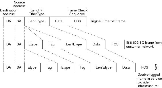
Using the EVCs, service providers can encapsulate packets that enter the service-provider network with multiple customer VLAN IDs (C-VLANs) and a single 0x8100 Ethertype VLAN tag with a service provider VLAN (S-VLAN). Within the service provider network, packets are switched based on the S-VLAN. When the packets egress the service provider network onto the customer network, the S-VLAN tag is decapsulated and the original customer packet is restored.

Figure 1 shows the tag structures of the double-tagged packets.

Figure 1. Original (Normal), 802.1Q, and Double-Tagged Ethernet Packet Formats

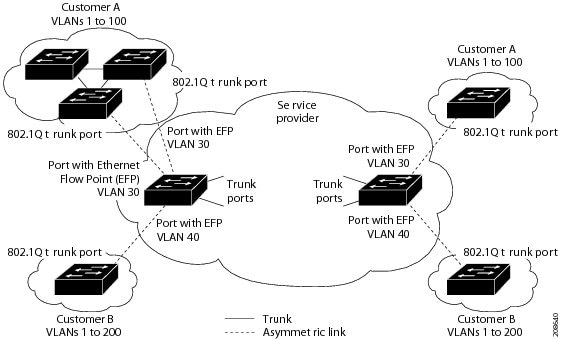
In Figure 2, Customer A is assigned VLAN 30, and Customer B is assigned VLAN 40. Packets entering the edge routers with 802.1Q tags are double-tagged when they enter the service-provider network, with the outer tag containing VLAN ID 30 or 40, appropriately, and the inner tag containing the original VLAN number, for example, VLAN 100. Even if both Customers A and B have VLAN 100 in their networks, the traffic remains segregated within the service-provider network because the outer tag is different. Each customer controls its own VLAN numbering space, which is independent of the VLAN numbering space used by other customers and the VLAN numbering space used by the service-provider network. At the outbound port, the original VLAN numbers on the customer's network are recovered.

Figure 2. 802.1Q Tunnel Ports in a Service-Provider Network

You can use EFPs to configure 802.1Q tunneling in two ways:

Example: Configuring IEEE 802.1Q Tunneling Using EFPs

In this example, for Customer A, interface Gigabit Ethernet 0/1 is the customer-facing port, and Gigabit Ethernet 0/2 is a trunk port facing the service provider network. For Customer B, Gigabit Ethernet 0/3 is the customer-facing port, and Gigabit Ethernet 0/4 is the trunk port facing the service provider network.

Customer A


Router(config)# interface gigabitethernet0/1 
Router(config-if)# service instance 1 Ethernet 
Router(config-if-srv)# encapsulation dot1q 1-100 
Router(config-if-srv)# bridge-domain 500
Router(config)# interface gigabitethernet0/2 
Router(config-if)# service instance 2 Ethernet 
Router(config-if-srv)# encapsulation dot1q 30 second-dot1q 1-100
Router(config-if-srv)# rewrite ingress pop 1 symmetric 
Router(config-if-srv)# bridge-domain 500

For Customer A, service instance 1 on Gigabit Ethernet port 0/1 is configured with the VLAN encapsulations used by the customer: C-VLANs 1–100. These are forwarded on bridge-domain 500. The service provider facing port is configured with a service instance on the same bridge-domain and with an encapsulation dot1q command matching the S-VLAN. The rewrite ingress pop 1 symmetric command also implies a push of the configured encapsulation on egress packets. Therefore, the original packets with VLAN tags between 1 and 100 are encapsulated with another S-VLAN (VLAN 30) tag when exiting Gigabit Ethernet port 0/2.

Similarly, for double- tagged (S-VLAN = 30, C-VLAN = 1–100) packets coming from the provider network, using the rewrite ingress pop 1 symmetric command enables the outer S-VLAN tag and forwards the original C-VLAN tagged frame over bridge-domain 500 out to Gigabit Ethernet port 0/1.

Customer B


Router(config)# interface gigabitethernet0/3 
Router(config-if)# service instance 1 Ethernet 
Router(config-if-srv)# encapsulation dot1q 1-200 
Router(config-if-srv)# bridge-domain 500
Router(config)# interface gigabitethernet0/4 
Router(config-if)# service instance 2 Ethernet 
Router(config-if-srv)# encapsulation dot1q 40 second-dot1q 1-200
Router(config-if-srv)# rewrite ingress pop 1 symmetric
Router(config-if-srv)# bridge-domain 500

Routed QinQ

Cisco ASR 901 router supports pop 2 configuration.

Restrictions

  • Pop 2 is not supported for MPLS, L2VPN, and MPLS VPN deployments.
  • ACL and QOS configurations for pop2 EVC scenarios are not supported.

Configuration Examples for Routed QinQ

This section provides the following sample configuration examples for routed QinQ on the Cisco ASR 901 router:

Example: User to Network Interface

Gig 0/1 (Connected to BTS)
interface GigabitEthernet0/1
service instance 1 ethernet
encapsulation dot1q 10
rewrite ingress tag pop 1 symmetric
bridge-domain 100
int vlan 100
ip address 1.1.1.1 255.255.255.0
Example: Network to Network Interface/Core Router

interface GigabitEthernet0/2
service instance 2 ethernet
encapsulation dot1q 20 second-dot1q 30
rewrite ingress tag pop 2 symmetric
bridge-domain 101
int vlan 101
ip address 2.2.2.2 255.255.255.0

In the above example:

  • The traffic coming from the Base Transceiver Station (BTS) through the GigabitEthernet interface 0/1 has the VLAN tag 10, which is popped and hits the Switch Virtual Interface (SVI) 100.This gets routed to SVI 101 depending on the destination address.
  • At the egress on the core interface, two tags (20 and 30) are pushed and sent out of GigabitEthernet interface 0/2, for SVI 101.
  • The traffic coming from the core router through GigabitEthernet interface 0/2, is destined to the BTS and has two tags (20,30); both tags get popped and hit SVI 101. This gets routed to SVI 100, which sends the traffic out of GigabitEthernet interface 0/1 with VLAN 10.
  • GigabitEthernet interface 0/2 can have multiple service instances and the traffic egresses out of the corresponding service instance depending on the SVI it gets routed to.

Bridge Domain Routing

The router supports IP routing for bridge domains, including Layer 3 and Layer 2 VPNs, using the SVI model.

Restrictions

  • You must configure SVIs for bridge-domain routing.
  • The bridge domain must be in the range of 1 to 4094 to match the supported VLAN range.
  • You cannot have any Layer 2 switchports in the VLAN (bridge domain) used for routing.
  • You can use bridge domain routing with only native packets.
  • MPLS is supported on EFP with SVI.
  • Scale limit for EFPs reduces if you use the second-dotlq command. Use the second-dotlq any command to maintain this limit.

Example: Configuring Bridge-Domain Routing

This is an example of configuring bridge-domain routing with a single tag EFP:


Router(config)# interface gigabitethernet0/2 
Router(config-if)# service instance 1 Ethernet 
Router(config-if-srv)# encapsulation dot1q 10 
Router(config-if-srv)# rewrite ingress tag pop 1 symmetric 
Router(config-if-srv)# bridge-domain 100
Router(config)# interface vlan 100
Router(config-if)# ip address 20.1.1.1 255.255.255.255

How to Configure DHCP Client on SVI

This section contains the following topics:

Configuring DHCP Client on SVI

To configure the DHCP client, the IP address, mask, broadcast address, and default gateway address of the SVI are retrieved from the server.

Complete the following steps to configure the DHCP client on SVI.

Procedure
  Command or Action Purpose
Step 1

enable

Example:

Router> enable

Enables privileged EXEC mode.

  • Enter your password if prompted.
Step 2

configure terminal

Example:

Router# configure terminal

Enters global configuration mode.

Step 3

interface vlan vlan-id

Example:

Router(config)# interface vlan 15

Configures the VLAN interface and enters interface configuration mode.

Step 4

ip address dhcp

Example:

Router(config-if)# ip address dhcp

Specifies an IP address through DHCP.

Step 5

interface type-number

Example:

Router(config-if)# interface GigabitEthernet0/7

Specifies an interface type number.

Step 6

service instance instance-id ethernet encapsulation dotlq vlan-id

Example:

Router(config-if)# service instance 10 
ethernet encapsulation dotlq 15

Creates a service instance on an interface and defines the matching criteria to be used in order to map the ingress dotlq frames to the appropriate service instance.

  • instance-id—Integer that uniquely identifies a service instance on an interface.
  • vlan-id—VLAN range is between 1 to 4094. You cannot use the same VLAN ID for more than one domain at the same level.
Step 7

rewrite ingress tag pop [1 | 2] symmetric

Example:

Router(config-if)# rewrite ingress tag pop 1 symmetric

Specifies the encapsulation adjustment to be performed on the frame ingress to the EFP. The symmetric keyword is required to complete the rewrite configuration.

Step 8

bridge-domain bridge-id

Example:

Router(config-if)# bridge-domain 15

Binds the service instance to a bridge domain instance using an identifier.

Verifying DHCP Client on SVI

To verify the configuration of DHCP client on SVI, use the show command described below.


Router# show ip-address interface brief | include vlan15

Interface	IP-Address	OK	  Method	Status	Protocol
Vlan15		  15.0.0.2	  YES	 DHCP	  up	    up

Example: Configuring DHCP Client on SVI


Router(config)# interface Vlan 15
Router(config-if)# ip address dhcp
Router(config-if)# interface GigabitEthernet0/7
Router(config-if)# negotiation auto
Router(config-if)# service instance 10 ethernet
Router(config-if-srv)# encapsulation dot1q 15
Router(config-if-srv)# rewrite ingress tag pop 1 symmetric
Router(config-if-srv)# bridge-domain 15

EFPs and MAC Addresses

To see MAC address information for VLANs 1 to 4094, use the show mac address-table vlan privileged EXEC command. For VLANs 4096 to 8000, use the show mac address-table bridge-domain privileged EXEC command. All other show mac address-table commands also support bridge domains as well as VLANs.

When an EFP property changes (bridge domain, rewrite, encapsulation, split-horizon, secured or unsecured, or a state change), the old dynamic MAC addresses are removed from their existing tables. This is to prevent old invalid entries from getting retained.

EFPs and MSTP

EFP bridge domains are supported by the Multiple Spanning Tree Protocol (MSTP). These restrictions apply when running MSTP with bridge domains.

  • All incoming VLANs (outer-most or single) mapped to a bridge domain must belong to the same MST instance or loops could occur.
  • For all EFPs that are mapped to the same MST instance, you must configure backup EFPs on every redundant path to prevent loss of connectivity due to STP blocking a port.
  • EVC only supports MSTP.

Monitoring EVC


Note

Statistics are not available in the service instance command. To look at flow statistics, you need to configure a class default policy on the service instance.
Table 2. Supported show Commands

Command

Description

show ethernet service evc [id evc-id | interface interface-id ] [detail ]

Displays information about all EVCs, or a specific EVC when you enter an EVC ID, or all EVCs on an interface when you enter an interface ID. The detail option provides additional information about the EVC.

show ethernet service instance [id instance-id interface interface-id | interface interface-id ] {[detail ] | [stats ]}

Displays information about one or more service instance (EFPs). If you specify an EFP ID and interface, only data pertaining to that particular EFP is displayed. If you specify only an interface ID, data is displayed for all EFPs on the interface.

show bridge-domain [n ]

Displays all the members of the specified bridge-domain, if a bridge-domain with the specified number exists.

If you do not enter n, the command displays all the members of all bridge-domains in the system.

show bridge-domain n split-horizon [group {group_id | all }]

Displays all the members of bridge-domain n that belong to split horizon group 0, when you do not specify a group group_id with this command.

If you specify a numerical group_id , this command displays all the members of the specified group id.

When you enter group all , the command displays all members of any split horizon group.

show ethernet service instance detail

This command displays detailed service instance information, including Layer 2 protocol information. This is an example of the output:


Router# show ethernet service instance detail 
Service Instance ID: 1
Associated Interface: Ethernet0/0
Associated EVC: 
L2protocol tunnel lacp 
 
CE-Vlans:                                                                        
State: Up
EFP Statistics:
   Pkts In   Bytes In   Pkts Out  Bytes Out
         0          0          0          0

show mac address-table

This command displays dynamically learned or statically configured MAC security addresses.

show mac address-table bridge-domain bridge-domain id

This command displays MAC address table information for the specified bridge domain.

show mac address-table count bridge-domain bridge-domain id

This command displays the number of addresses present for the specified bridge domain.

show mac address-table learning bridge-domain bridge-domain id

This command displays the learning status for the specified bridge domain.

Example

This is an example of output from the show ethernet service instance detail command:


Router# show ethernet service  instance id 1 interface gigabitEthernet 0/1 detail 
Service Instance ID: 1
Associated Interface: GigabitEthernet0/13
Associated EVC: EVC_P2P_10
L2protocol drop
CE-Vlans: 
Encapsulation: dot1q 10 vlan protocol type 0x8100
Interface Dot1q Tunnel Ethertype: 0x8100
State: Up
EFP Statistics:
   Pkts In   Bytes In   Pkts Out  Bytes Out
       214      15408      97150    6994800
EFP Microblocks:
****************
Microblock type: Bridge-domain
Bridge-domain: 10

This is an example of output from the show ethernet service instance statistics command:


Router# show ethernet service  instance id 1 interface gigabitEthernet  0/13  stats
Service Instance 1, Interface GigabitEthernet0/13
Pkts In   Bytes In   Pkts Out  Bytes Out
       214      15408      97150    6994800

This is an example of output from the show mac-address table count command:


Router# show mac address-table count bridge-domain 10
Mac Entries for BD   10:
---------------------------
Dynamic Address Count  : 20
Static  Address Count  : 0
Total Mac Addresses : 20

Configuring Switchport to EVC Mapping

This example illustrates EVC in a UNI layer, 802.1q tunneling towards aggregation and QoS classification with marking and policing at ingress port. A two level HQoS policy is applied on the ingress.

In this example, all the switchport configurations of the ME3400/MWR2941 have been converted into EVC based equivalent configuration for GigabitEthernet interface 0/0. This is the ingress port connected to the nodes. Therefore, instead of switchport access vlan there is an EVC configured using the service instance command under the physical interface.

The GigabitEthernet interface 0/9 has the egress port configuration which has 802.1q tunneling configured. This port is connected to the aggregation device. This is the fundamental difference in configuration between the Cisco ME34xx devices and the Cisco ASR 901 router. All configurations can be modeled along this sample working configuration.

Example: Configuring Switchport to EVC Mapping


class-map match-any CELL-TRFC
 match vlan  2615 3615
!
policy-map INPUT-SUBMAP
 class CELL-TRFC
  police cir 60000000 bc 1875000
   conform-action transmit
   exceed-action drop
policy-map INPUT-TOPMAP
 class class-default
  police cir 90000000 conform-action transmit  exceed-action drop
  service-policy INPUT-SUBMAP
policy-map INPUT-MAP
 class class-default
  police cir 60000000 bc 1875000
   conform-action transmit
   exceed-action drop
!
!
interface GigabitEthernet0/0
 no negotiation auto
 service instance 2615 ethernet
  encapsulation dot1q 2615
  service-policy input INPUT-TOPMAP
  bridge-domain 2615
 !
 service instance 3615 ethernet
  encapsulation dot1q 3615
  service-policy input INPUT-MAP
  bridge-domain 3615
 !
!
interface GigabitEthernet0/1
 no negotiation auto
!
interface GigabitEthernet0/2
 no negotiation auto
!
interface GigabitEthernet0/3
 no negotiation auto
!
interface GigabitEthernet0/4
 no negotiation auto
!
interface GigabitEthernet0/5
 no negotiation auto
!
interface GigabitEthernet0/6
 no negotiation auto
!
interface GigabitEthernet0/7
 no negotiation auto
!
interface GigabitEthernet0/8
 no negotiation auto
!
interface GigabitEthernet0/9
 no negotiation auto
 service instance 2615 ethernet
  encapsulation dot1q 100 second-dot1q 2615
  rewrite ingress tag pop 1 symmetric
  bridge-domain 2615
 !
 service instance 3615 ethernet
  encapsulation dot1q 100 second-dot1q 3615
  rewrite ingress tag pop 1 symmetric
  bridge-domain 3615
 !
!
interface GigabitEthernet0/10
 no negotiation auto
!
interface GigabitEthernet0/11
 no negotiation auto
!
interface ToP0/12
 no negotiation auto
!
interface FastEthernet0/0
 full-duplex
!
interface Vlan1
!
ip forward-protocol nd
!
!
no ip http server
!
logging esm config
!
!
!
control-plane
!
!
line con 0
line con 1
 transport preferred lat pad telnet rlogin udptn mop ssh
 transport output lat pad telnet rlogin udptn mop ssh
line vty 0 4
 login
!
exception data-corruption buffer truncate
exception crashinfo buffersize 128
!
end

Troubleshooting DHCP Snooping with Option-82 on EVC

Use the following debug commands to troubleshoot the DHCP Snooping with Option-82 on EVC feature configuration on the Cisco ASR 901 router:


Note

We suggest you do not use the debug command without TAC supervision.


Command Purpose

debug ip dhcp snooping

Additional References

The following sections provide references related to Configuring EVC feature.

Related Documents

Related Topic

Document Title

Cisco IOS Commands

Cisco IOS Master Commands List, All Releases

Cisco ASR 901 Command Reference

Cisco ASR 901 Series Aggregation Services Router Command Reference

Cisco IOS Interface and Hardware Component Commands

Cisco IOS Interface and Hardware Component Command Reference

Standards

Standard

Title

None

MIBs

MIB

MIBs Link

None

To locate and download MIBs for selected platforms, Cisco IOS releases, and feature sets, use Cisco MIB Locator found at the following URL:

http://www.cisco.com/go/mibs

RFCs

RFC

Title

None

Technical Assistance

Description

Link

The Cisco Technical Support website contains thousands of pages of searchable technical content, including links to products, technologies, solutions, technical tips, and tools. Registered Cisco.com users can log in from this page to access even more content.

http://www.cisco.com/techsupport

Feature Information for Configuring Ethernet Virtual Connections

The following table lists the features in this module and provides links to specific configuration information.

Use Cisco Feature Navigator to find information about platform support and software image support. Cisco Feature Navigator enables you to determine which software images support a specific software release, feature set, or platform. To access Cisco Feature Navigator, go to http://www.cisco.com/go/cfn . An account on Cisco.com is not required.


Note

The following table lists only the software release that introduced support for a given feature in a given software release train. Unless noted otherwise, subsequent releases of that software release train also support that feature.
Table 3. Feature Information for Configuring Ethernet Virtual Connections

Feature Name

Releases

Feature Information

Configuring Ethernet Virtual Connections

15.2(2)SNH1

See the following links for more information about this feature:

EVC Default Encapsulation

15.3(2)S

See the following links for more information about this feature:

DHCP Snooping with Option-82 on EVC

15.4(3)S

See the following links for more information about this feature: