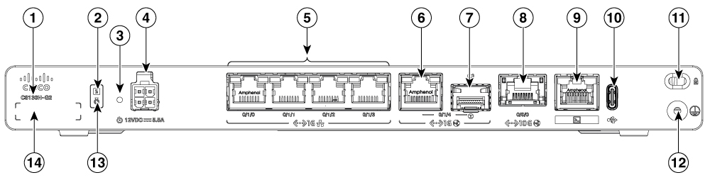
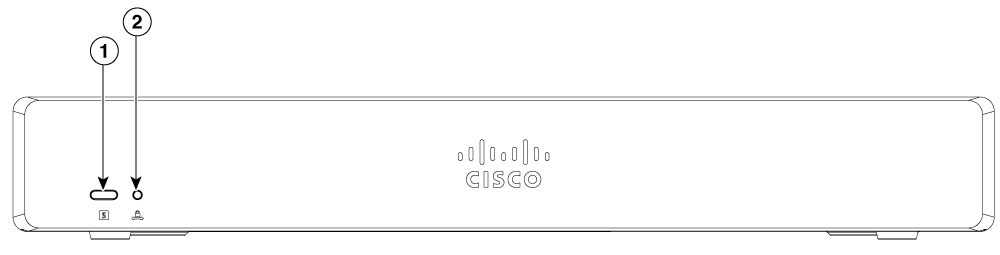
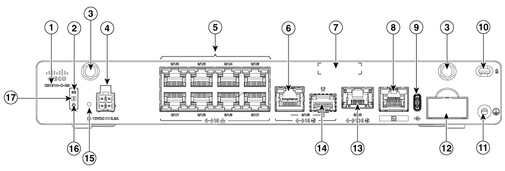
Details the physical layout and components of the router chassis, highlighting front and rear panels, key visual elements, and overall hardware structure for easier identification and maintenance.
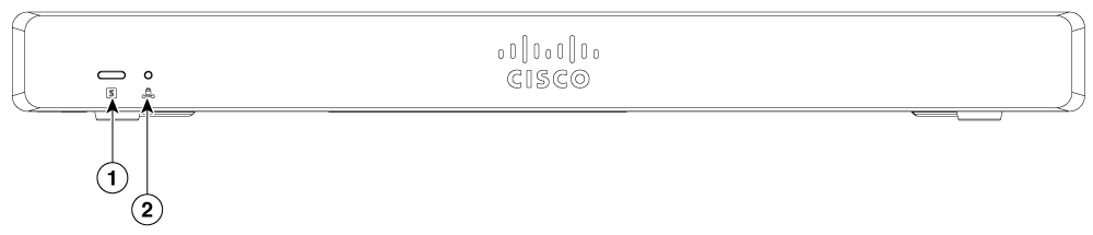
|
1 |
System status |
2 |
VPN |
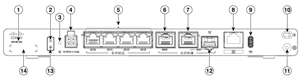
|
1 |
Product Identification Number (PID) |
2 |
System status |
|
3 |
Reset button |
4 |
4-Pin power connector |
|
5 |
GE RJ45 0/1/0 to 0/1/3 |
6 |
GE 0/0/0 - RJ45 |
|
7 |
GE 0/0/1 - RJ45 |
8 |
RJ45 console port |
|
9 |
USB-C 3.0 |
10 |
Kensington lock slot |
|
11 |
Grounding |
12 |
GE 0/0/1 - SFP |
|
13 |
Blue beacon |
14 |
Serial number |
|
1 |
System status |
2 |
VPN |
|
1 |
Product Identification Number (PID) |
2 |
System status |
|
3 |
Reset button |
4 |
4-Pin power connector |
|
5 |
GE RJ45 0/1/0 to 0/1/3 |
6 |
GE 0/0/0 - RJ45 |
|
7 |
GE 0/0/1 - RJ45 |
8 |
RJ45 console port |
|
9 |
USB-C 3.0 |
10 |
Kensington lock slot |
|
11 |
Grounding |
12 |
GE 0/0/1 - SFP |
|
13 |
Blue beacon |
14 |
Serial number |
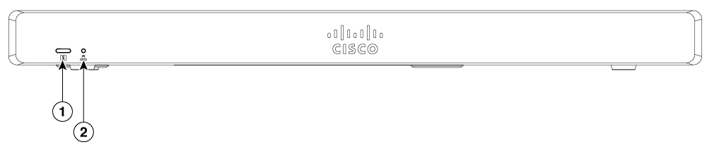
|
1 |
System status |
2 |
VPN |
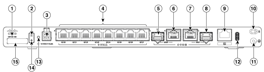
|
1 |
Product Identification Number (PID) |
2 |
System status |
|
3 |
4-Pin power connector |
4 |
GE RJ45 0/1/0 to 0/1/7 |
|
5 |
GE 0/0/0 - SFP |
6 |
GE 0/0/0 - RJ45 |
|
7 |
GE 0/0/1 - RJ45 |
8 |
GE 0/0/1 - SFP |
|
9 |
RJ45 console port |
10 |
Kensington lock slot |
|
11 |
Grounding |
12 |
USB-C 3.0 |
|
13 |
Reset button |
14 |
Blue beacon |
|
15 |
Serial number |
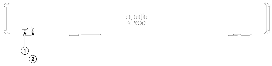
|
1 |
System status |
2 |
VPN |
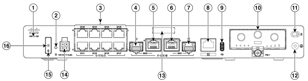
|
1 |
Product Identification Number (PID) |
2 |
Reset button |
|
3 |
GE RJ45 0/1/0 to 0/1/7 |
4 |
GE 0/0/0 - SFP |
|
5 |
GE 0/0/0 - RJ45 |
6 |
GE 0/0/1 - RJ45 |
|
7 |
GE 0/0/1 - SFP |
8 |
RJ45 console port |
|
9 |
USB-C 3.0 |
10 |
PIM module |
|
11 |
Kensington lock slot |
12 |
Grounding |
|
13 |
Serial number |
14 |
4-Pin power connector |
|
15 |
Blue beacon |
16 |
System status |
|
1 |
System status |
2 |
VPN |
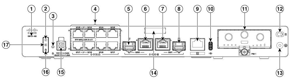
|
1 |
Product Identification Number (PID) |
2 |
POE PSU status LED |
|
3 |
Reset button |
4 |
GE RJ45 0/1/0 to 0/1/7 |
|
5 |
GE 0/0/0 - SFP |
6 |
GE 0/0/0 - RJ45 |
|
7 |
GE 0/0/1 - RJ45 |
8 |
GE 0/0/1 - SFP |
|
9 |
RJ45 console port |
10 |
USB-C 3.0 |
|
11 |
PIM module |
12 |
Kensington lock slot |
|
13 |
Grounding |
14 |
Serial number |
|
15 |
4-Pin power connector |
16 |
Blue beacon |
|
17 |
System status |
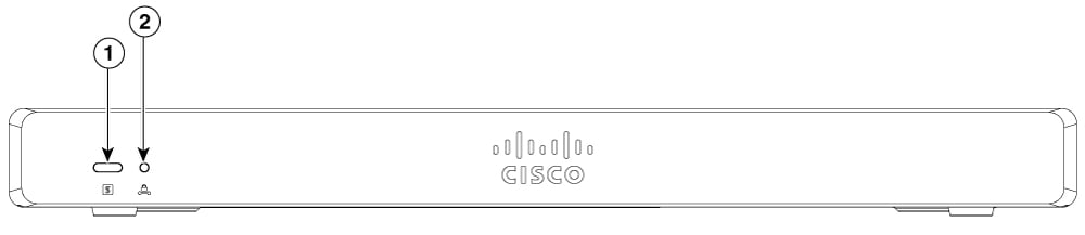
|
1 |
System status |
2 |
VPN |
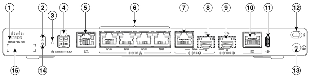
|
1 |
Product Identification Number (PID) |
2 |
System status |
|
3 |
Reset button |
4 |
4-Pin power connector |
|
5 |
RJ11 DSL Port |
6 |
GE RJ45 0/1/0 to 0/1/3 |
|
7 |
GE 0/1/4 - RJ45 |
8 |
GE 0/1/4 - SFP |
|
9 |
TE 0/0/0 - XGSPON/10GBASE-T |
10 |
RJ45 console port |
|
11 |
USB-C 3.0 |
12 |
Kensington lock slot |
|
13 |
Grounding |
14 |
Blue beacon |
|
15 |
Serial number |
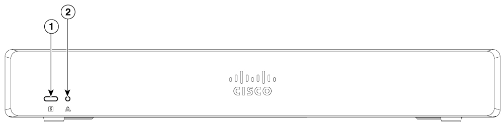
|
1 |
System status |
2 |
VPN |
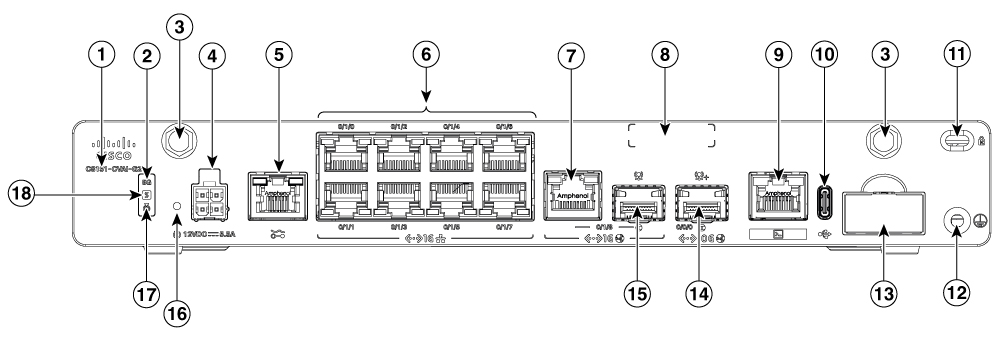
|
1 |
Product Identification Number (PID) |
2 |
5G LED Indicator |
|
3 |
Antenna SMA connector |
4 |
4-Pin power connector |
|
5 |
RJ11 DSL Port |
6 |
GE RJ45 0/1/0 to 0/1/7 |
|
7 |
GE 0/1/8 - RJ45 |
8 |
Serial number |
|
9 |
RJ45 console port |
10 |
USB-C 3.0 |
|
11 |
Kensington lock slot |
12 |
Grounding |
|
13 |
Dual nano SIM card slot |
14 |
TE 0/0/0 - XGSPON/10GBASE-T |
|
15 |
GE 0/1/8 - SFP |
16 |
Reset button |
|
17 |
Blue beacon |
18 |
System status |
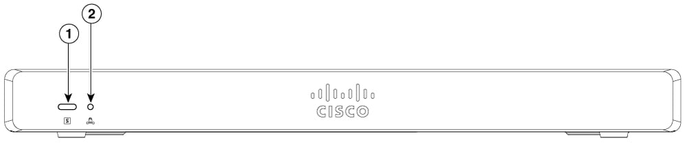
|
1 |
System status |
2 |
VPN |
|
1 |
Product Identification Number (PID) |
2 |
System status |
|
3 |
Reset button |
4 |
4-Pin power connector |
|
5 |
GE RJ45 0/1/0 to 0/1/3 |
6 |
GE 0/1/4 - RJ45 |
|
7 |
GE 0/1/4 - SFP |
8 |
Te0/0/0 copper |
|
9 |
RJ45 console port |
10 |
USB-C 3.0 |
|
11 |
Kensington lock slot |
12 |
Grounding |
|
13 |
Blue beacon |
14 |
Serial number |
|
1 |
System status |
2 |
VPN |
|
1 |
Product Identification Number (PID) |
2 |
5G LED Indicator |
|
3 |
Antenna SMA connector |
4 |
4-Pin power connector |
|
5 |
GE RJ45 0/1/0 to 0/1/7 |
6 |
GE 0/1/8 - RJ45 |
|
7 |
Serial number |
8 |
RJ45 console port |
|
9 |
USB-C 3.0 |
10 |
Kensington lock slot |
|
11 |
Grounding |
12 |
Dual nano SIM card slot |
|
13 |
Te0/0/0 copper |
14 |
GE 0/1/8 - SFP |
|
15 |
Reset button |
16 |
Blue beacon |
|
17 |
System status |