Hardware Installation Guide for the Cisco 8100 Series Secure Routers

PDF

Hardware Installation Guide for the Cisco 8100 Series Secure Routers

Remove and replace the battery

Want to summarize with AI?

Log in

Details proper handling, removal, and replacement procedures for batteries, emphasizing safety considerations and compliant disposal of battery units from the routers.


These instructions are provided in order to comply with the EU Battery Replaceability Requirement.

  • This product was not specifically designed for battery replacement in the field.

  • It is recommended that, whenever possible, follow the standard repair or return process for battery issues.

Caution

Always wear an ESD-preventive wrist strap and ensure that it makes good contact with your skin when you remove or install the internal modules. Connect the equipment end of the wrist strap to the metal part of the chassis.

Caution

The process to replace the battery may incur risk to the integrity of the product due to the detachment of thermal interface material used to cool components on the printed circuit board (PCB). Through this process, pay close attention to thermal interface materials that may become loose and fall out of place. Reattach fallen thermal interface materials in the exact location they were originally in without over compressing them.
Disassemble the router

You may need to disassemble the router to access internal components such as the PCB, replace modules, or troubleshoot hardware issues. Follow these steps to disassemble the router.

Procedure

1.

Disconnect, power down and remove the router from any mounting kits. Remove any optical modules, antennas or PIMs that are in use.

2.

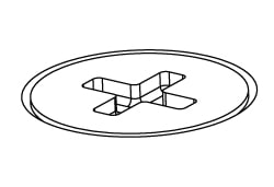
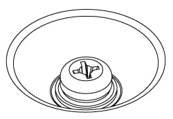
Place the router in front of you with the IO facing away. Remove all screws on the base while noting which screw type goes where for ease of reassambly.

Flat head screw

Pan head screw
3.

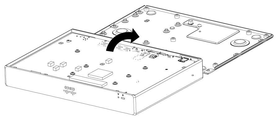
Remove the base and place on the other side of the router with the feet on the table.

Figure 1. Remove the base
4.

Remove the screws for the PCB.

5.

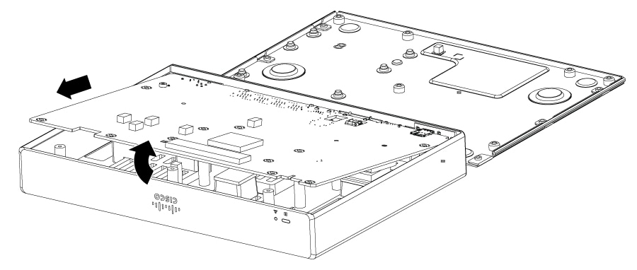
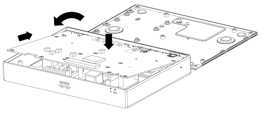
Double check that all the screws have been removed. Lift up the PCB from the non-IO side first and remove it at an angle so that the connectors can clear the chassis.

Figure 2. Remove PCB at an angle
6.

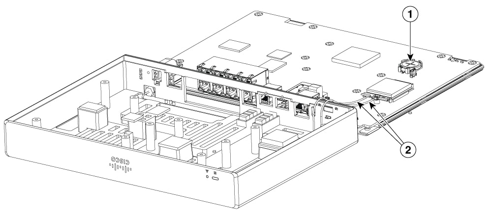
Place the PCB face up on the base. If your router has embedded cellular capabilities, be mindful of any antenna wires that are attached to the cover. If any antenna wires disconnect from the modem on the PCB, ensure they are correctly connected before reassembly.

Figure 3. Place the PCB on the base

1

Battery

2

Antenna wires


Remove the battery

Perform this procedure when the battery requires replacement or maintenance on supported hardware.

Note

Follow proper electrostatic discharge (ESD) precautions before handling the battery or device.

Wear an ESD-preventive wrist strap, ensuring that it makes good skin contact. Connect the clip to an unpainted surface of the chassis frame to channel unwanted ESD voltages safely to ground. To guard against ESD damage and shocks, the wrist strap and cord must operate effectively.

Warning

Statement 1015—Battery Handling

To reduce risk of fire, explosion or leakage of flammable liquid or gas:

  • Replace the battery only with the same or equivalent type recommended by the manufacturer.

  • Do not dismantle, crush, puncture, use sharp tool to remove, short external contacts, or dispose of in fire.

  • Do not use if battery is warped or swollen.

Procedure

1.

Before you perform any module replacement, read the Safety Warnings section and disconnect the power supplies.

2.

Identify the type of battery holder and follow the instructions accordingly.

3.

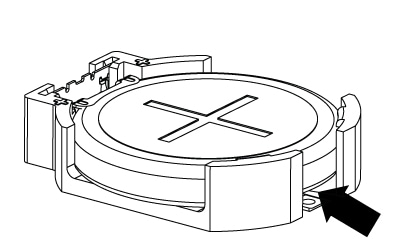
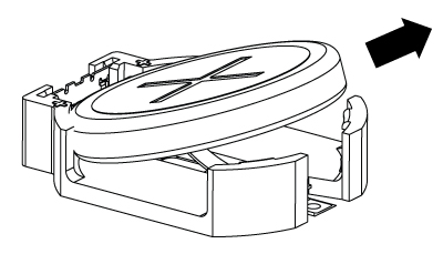
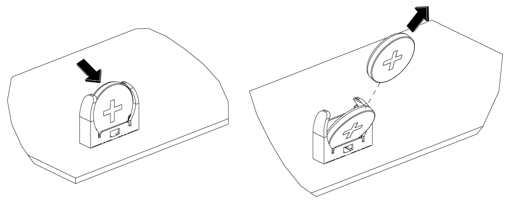
For Battery Holder type 1, follow these instructions to remove the battery:

  1. Slide the battery in the direction shown to clear the clips in the holder. A small flat head screw driver maybe used where the arrow points to.

  2. Pull the battery out at an angle.

4.

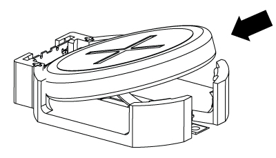
For Battery Holder type 2, follow these instructions to remove the battery:

  1. Pivot the battery in the direction shown.

  2. Pull the battery out at an angle.

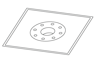
    Figure 4. Remove the battery

Replace the battery

Replace the battery in the chassis following the safety procedures to ensure proper device functionality.
Note

Follow proper electrostatic discharge (ESD) precautions before handling the battery or device.

Before you begin

  • There are two types of battery holders that may be present on the PCBA. Identify the correct type and refer to the instructions specific to that type.

  • The battery is a CR2032 type. Batteries should only be replaced with the same or an equivalent type recommended by the manufacturer.

    • For C8130-G2, C8131-G2 and C8140-G2:

      • Panasonic CR-2032L/ZBS

      • Renata 100932

    • For C8151-G2 and C8161-G2:

      • Renata 100272

      • Varata Microbattery Inc. 06032 101 501

    • For C8130-VAI-G2, C8130-VAP-G2, C8151-CVAI-G2 and C8151-CVAP-G2:

      • Maxell CR2032 MAXELL

      • KTS BBR2032

Procedure

1.

Read the Safety Warnings instructions and disconnect the power supplies before you perform any module replacement.

2.

Identify the type of battery holder and follow the instructions accordingly.

3.

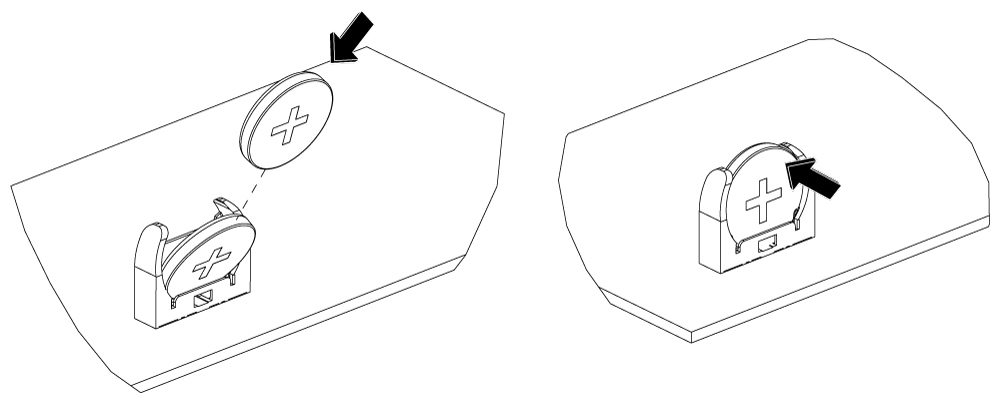
For Battery Holder type 1, follow these instructions to replace the battery:

  1. Orient the battery with positive polarity as shown.

  2. Angle the battery so you can insert the edge of the battery into the holder base.

  3. Rotate the battery and press into the base in the same motion to install the battery firmly in the holder.

4.

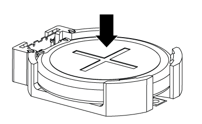
For Battery Holder type 2, follow these instructions to replace the battery:

  1. Orient the battery with positive polarity as shown.

  2. Angle the battery so you can insert the edge of the battery into the holder base.

  3. Rotate the battery and press into the base in the same motion to install the battery firmly in the holder.

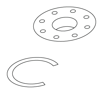
Figure 5. Install the battery

Reassemble the router

Use this task after completing maintenance or replacing components in your router. Proper reassembly ensures the router functions as intended and prevents hardware issues.

Procedure

1.

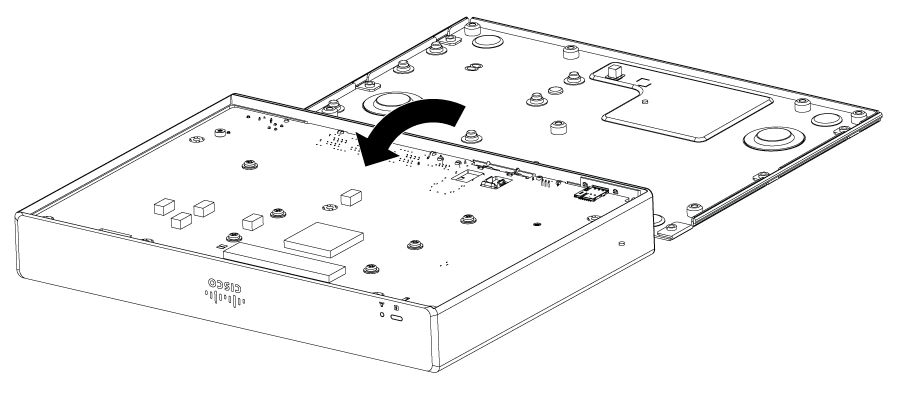
Replace the PCB into the cover by flipping it upside down, angling the PCB into the IO connectors first then laying it flat. Ensure antenna wires are not pinched between the PCB and any mounting holes in the cover.

Figure 6. Replace PCB into the cover
2.

Secure the PCB screws. Note that these screw holes on the PCB are indicated by silkscreen markers to indicate which holes need screws at this step.

Square marking

'C' marking

3.

Place the base on the PCB and attach with remaining screws.

Figure 7. Install base
4.

Install any accessories that were removed for this procedure. You may use the router as intended.