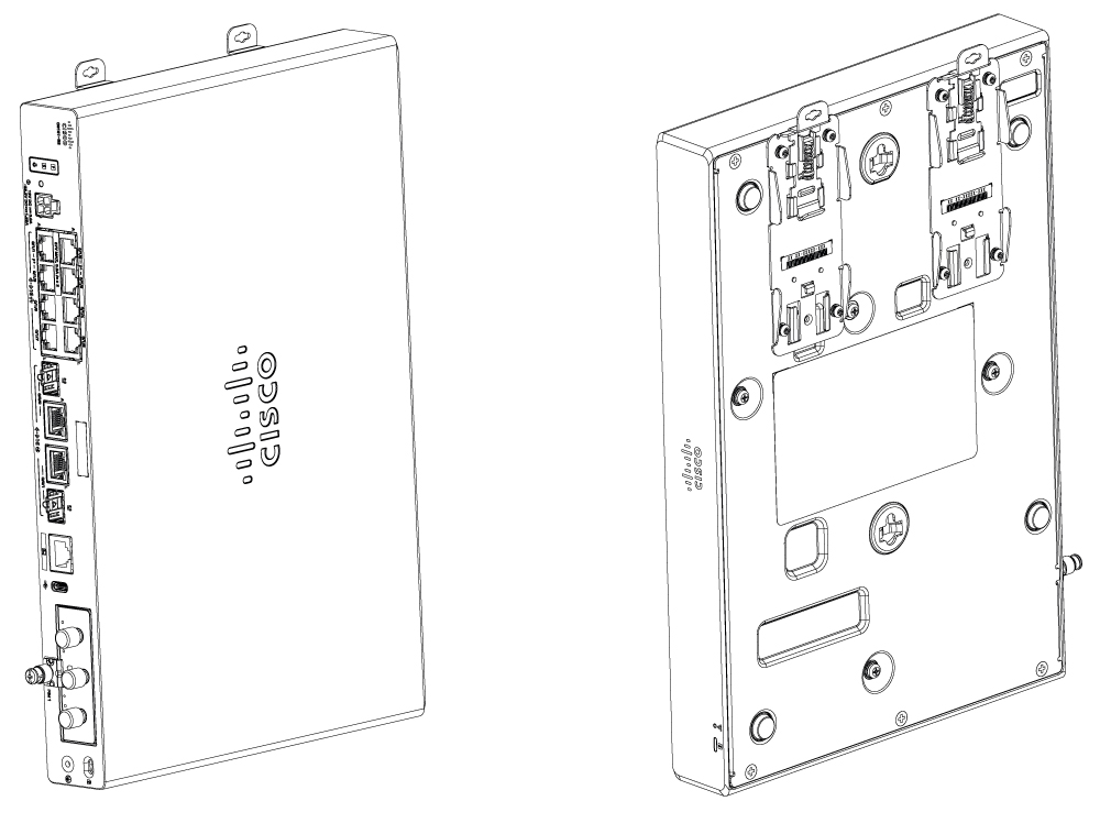
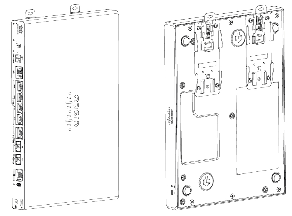
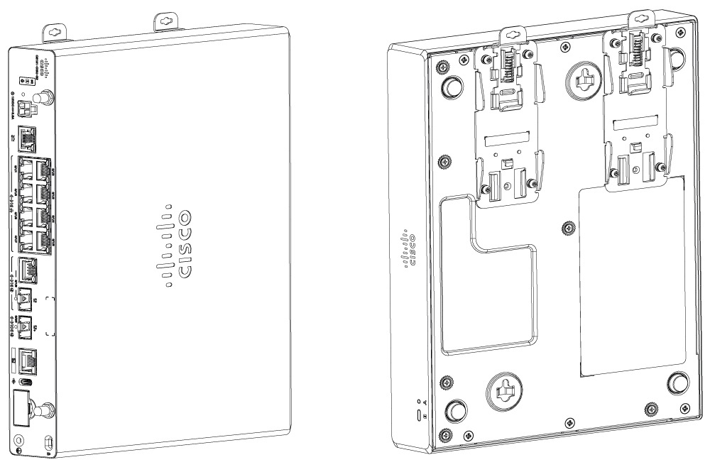
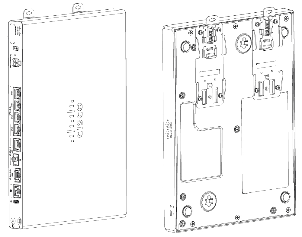
Hardware Installation Guide for the Cisco 8100 Series Secure Routers

PDF

Hardware Installation Guide for the Cisco 8100 Series Secure Routers

Install the router

Want to summarize with AI?

Log in

Details mounting and installation procedures for desktop, rack, under-desk, shelf, and wall setups, including guidance on bracket attachment, chassis grounding, safety warnings for ground and optical connections, and required installation tasks.


After unpacking, based on your requirements, you can set up the Cisco 8100 Series Secure Router under-desk, on a desktop, a rack, or the wall.

Note

You can install external modules before or after mounting a router. However, if you choose to install the external modules after mounting the router on the rack or wall, ensure that you have optimal access to the back/front panel of the router.

Note

To prevent the system from overheating, do not operate the device in an area that exceeds a local ambient of 40°C. For altitudes above sea-level, de-rate the ambient operating temperature by 1°C per 1000-feet of elevation.

Note

When mounting a Cisco 8100 Series Secure Router, the local ambient should be measured 2-inches below the fully mounted product when possible. When this is not possible the local ambient should be measured 2-inches from the I/O side of the product.

Note

The product's surface temperature may be elevated at higher throughputs; however, the product is operating as expected.

Module

Mounting Options

C8130-G2

Desktop, Rack mount, Under Desk/Shelf Mount, Wall mount using Key-hole slots, Wall mount DIN-rail brackets

C8131-G2

C8140-G2

C8151-G2

C8161-G2

C8130-CVAI-G2

C8130-VAP-G2

C8151-CVAI-G2

C8151-CVAP-G2


Desktop

If you choose to setup the router on a desktop, you can place the router on a desktop, bench top, or shelf.

Caution

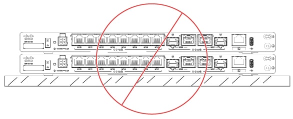
Do not place anything on top of the device and do not stack devices on a desktop, else, this causes the product to overheat.


Rack mount

Secure rack mounting brackets on the chassis before you set up the chassis on the rack.

Caution

Do not stack multiple Cisco 8100 Series Secure Routers when mounting the routers on a tabletop.

Do not put any object on the sides or on top of the routers ensuring that there is ample space for air circulation and heat removal. Your chassis installation must allow unrestricted airflow for chassis cooling.

Periodic Inspection and Cleaning:

We recommend that you periodically inspect and clean the external surface of the router. Removing is recommended to minimize the negative impact of environmental dust, debris, and liquid contamination. The frequency of inspection and cleaning is dependent upon the severity of the environmental conditions, but we recommend cleaning the router once every six months.

Note

Sites with ambient temperatures consistently above 25°C or 77°F and with potentially high levels of dust or debris might require periodic preventative maintenance cleaning.

Note

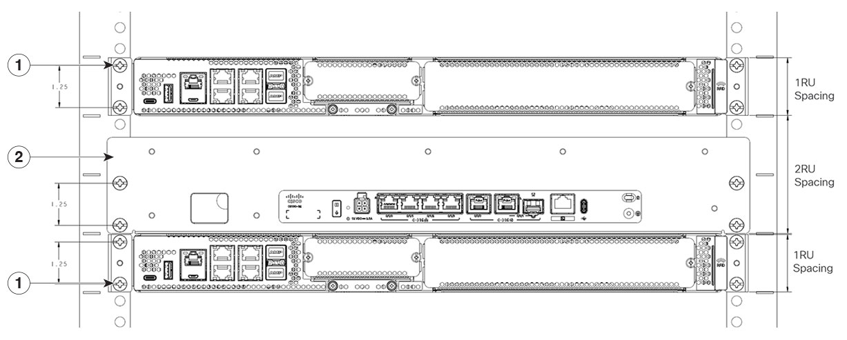
When mounting Cisco 8100 Series Secure Routers on a rack, ensure at least one rack unit (1RU) of vertical space between routers. This ensures more heat removal, which in turn helps the surrounding air temperature to stay within the specified operating conditions.

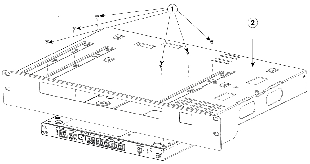
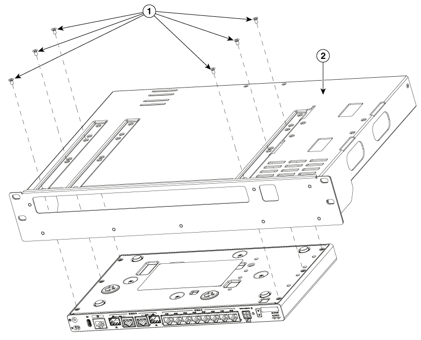
Figure 1. Rack-tray assembly

1

Typical 1RU Product (reference only)

2

Rack-tray installed


Attach the rack mount brackets

This procedure describes how to attach the brackets on the router chassis:

Procedure

1.

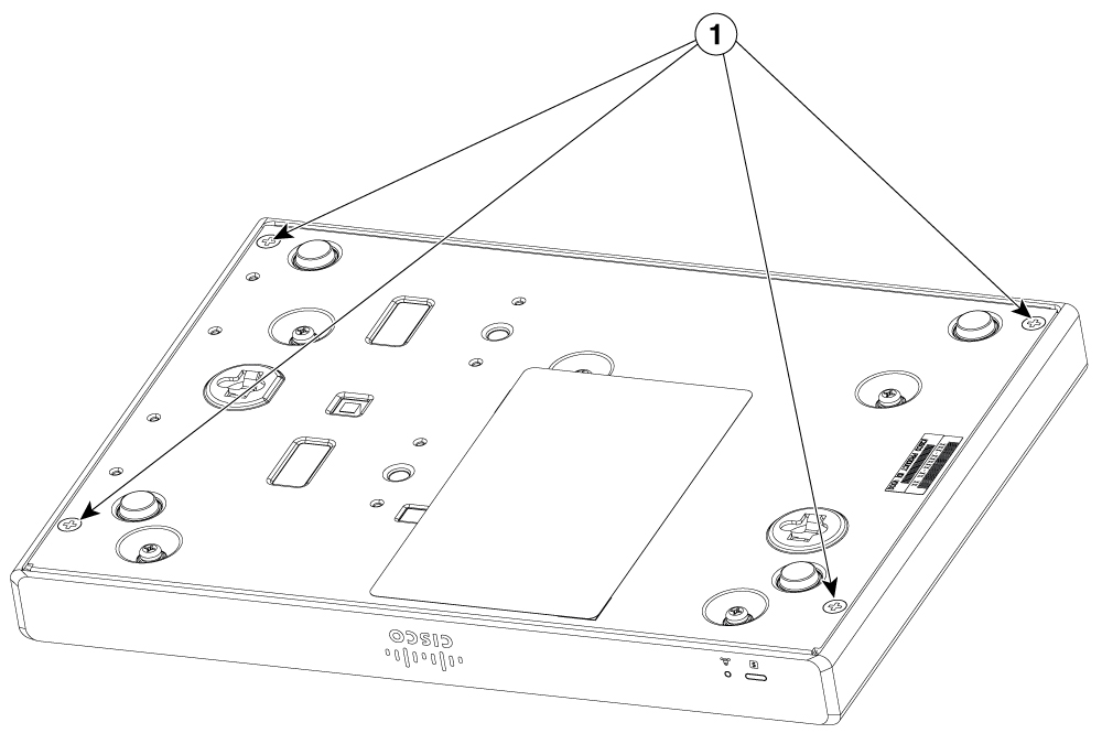
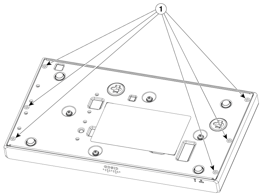
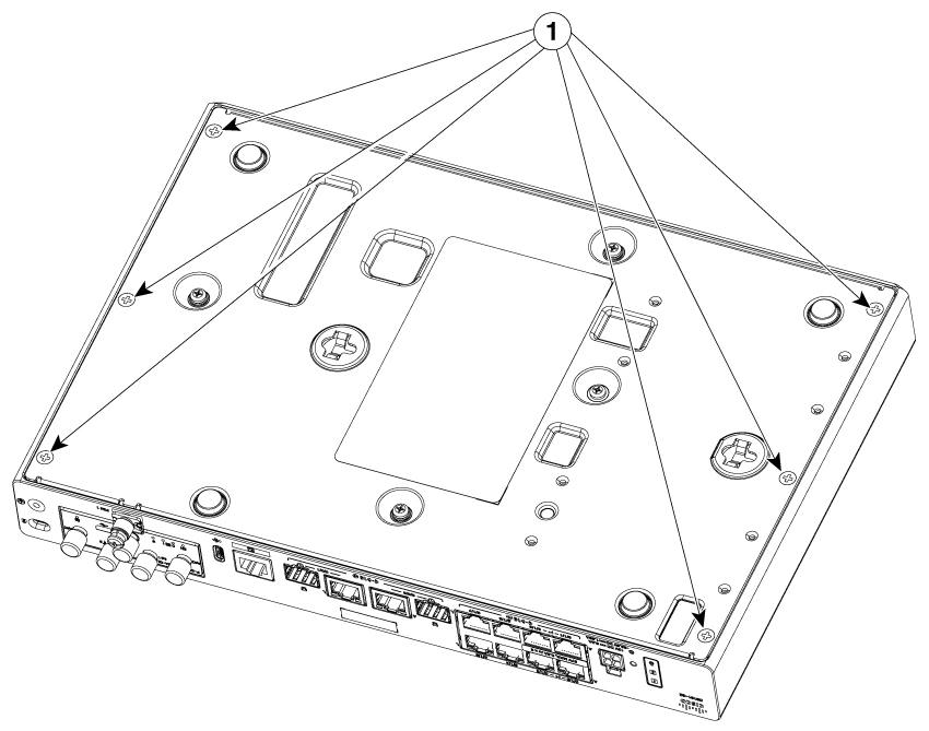
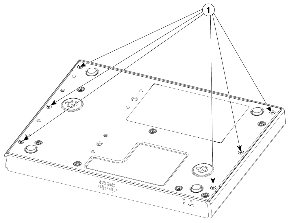
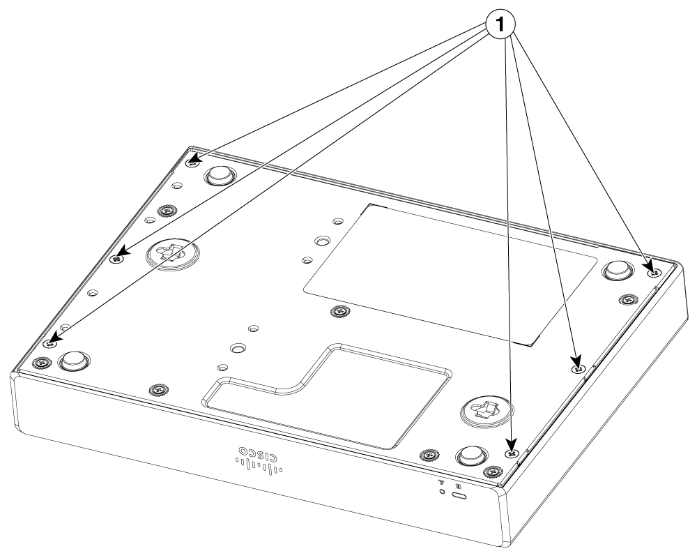
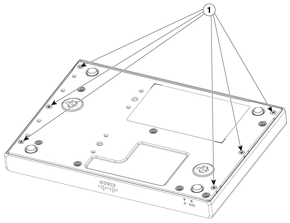
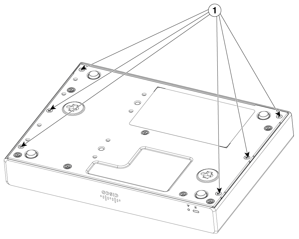
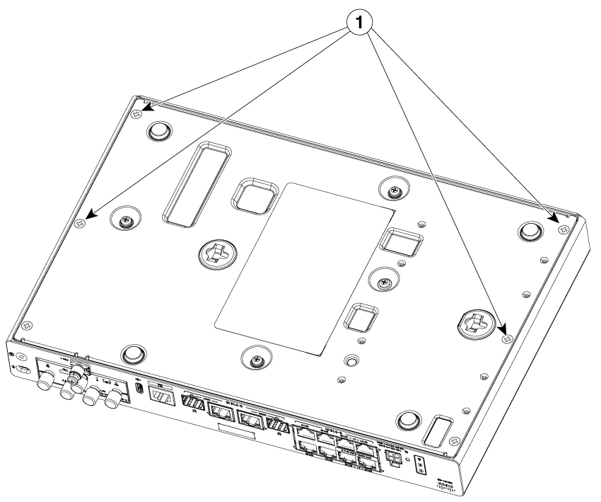
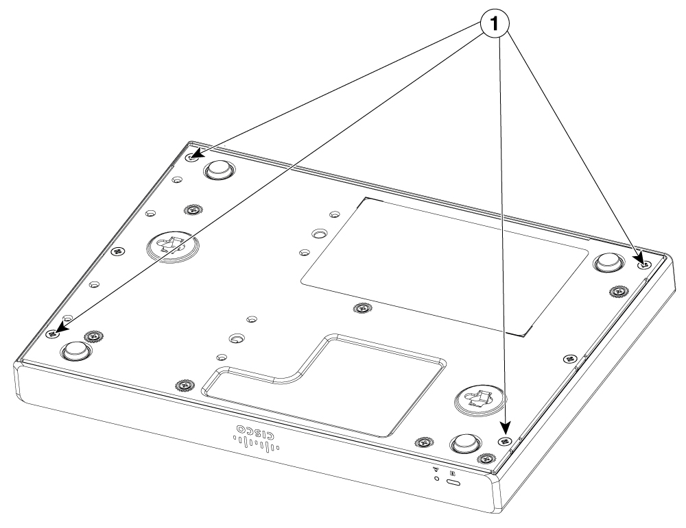
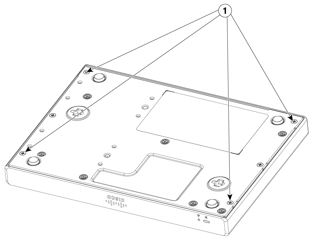
Remove the screws from the bottom of the chassis as per shown in these figures.

Example:

Figure 2. Removing screws from C8130-G2 and C8131-G2

1

Screws

Example:

Figure 3. Removing screws from C8140-G2

1

Screws

Example:

Figure 4. Removing screws from C8151-G2 and C8161-G2

1

Screws

Example:

Figure 5. Removing screws from C8130-VAI-G2 and C8130-VAP-G2

1

Screws

Example:

Figure 6. Removing screws from C8151-CVAI-G2 and C8151-CVAP-G2

1

Screws

2.

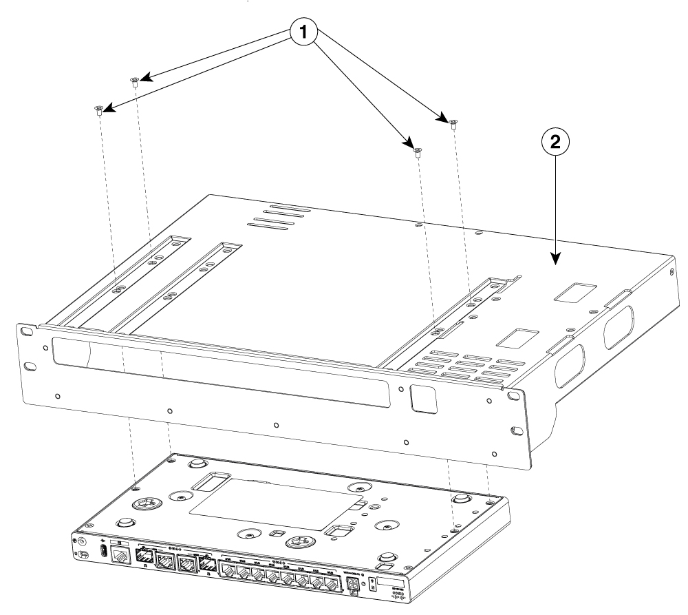
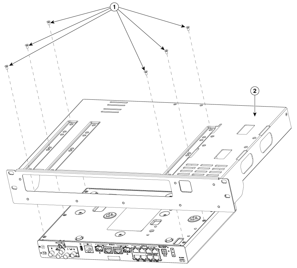
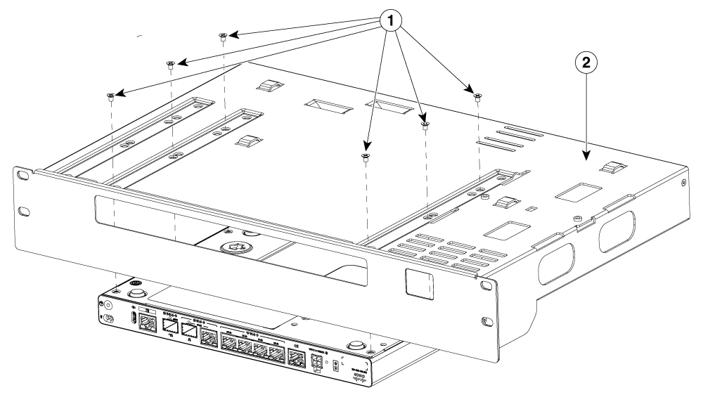
Align the bracket to the indicated holes of the chassis.

3.

Secure the bracket to the router using the screws that were removed.

Example:

Figure 7. Rack mounting bracket installation for C8130-G2 and C8131-G2

1

Screws

2

Brackets

Example:

Figure 8. Rack mounting bracket installation for C8140-G2

1

Screws

2

Brackets

Example:

Figure 9. Rack mounting bracket installation for C8151-G2 and C8161-G2

1

Screws

2

Brackets

Example:

Figure 10. Rack mounting bracket installation for C8130-VAI-G2 and C8130-VAP-G2

1

Screws

2

Brackets

Example:

Figure 11. Rack mounting bracket installation for C8151-CVAI-G2 and C8151-CVAP-G2

1

Screws

2

Brackets


Mount the router

Before you begin

Before mounting the router on to the rack, refer to these safety warning statements:

Warning

Statement 1006—Chassis Warning for Rack-Mounting and Servicing

To prevent bodily injury when mounting or servicing this unit in a rack, you must take special precautions to ensure that the system remains stable. The following guidelines are provided to ensure your safety:

  • This unit should be mounted at the bottom of the rack if it is the only unit in the rack.

  • When mounting this unit in a partially filled rack, load the rack from the bottom to the top with the heaviest component at the bottom of the rack.

  • If the rack is provided with stabilizing devices, install the stabilizers before mounting or servicing the unit in the rack.

Procedure

To install the router, use the screws provided with the accessory kit to secure the router when you mount it over the rack.


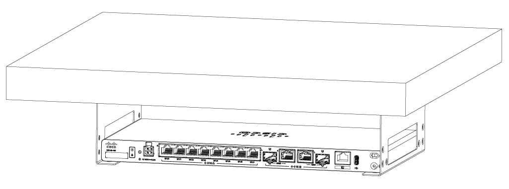
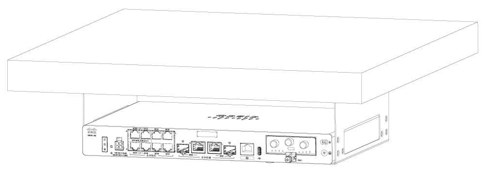
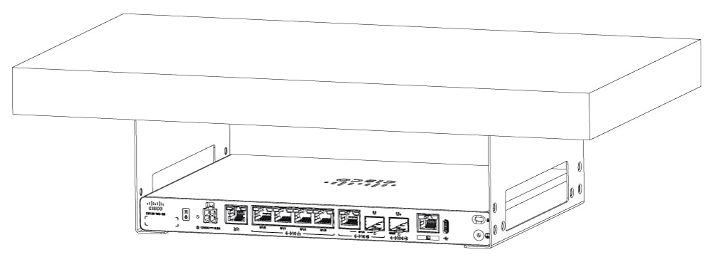
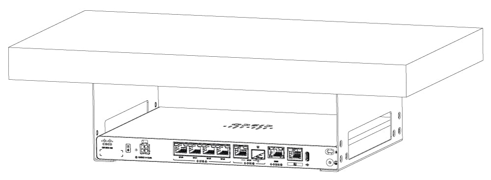
Under desk or shelf mount

Installing the router under a desk requires an optional bracket kit that is not included with the router. The kit contains the under-desk brackets and screws to secure the brackets to the bottom of the desk. You can order these kits from your Cisco representative. This procedure describes how to mount a router under a desk or a shelf.

Procedure

1.

Remove the screws from the bottom of the chassis.

Example:

Figure 12. Removing screws from C8130-G2 and C8131-G2

1

Screws

Example:

Figure 13. Removing screws from C8140-G2

1

Screws

Example:

Figure 14. Removing screws from C8151-G2 and C8161-G2

1

Screws

Example:

Figure 15. Removing screws from C8130-VAI-G2 and C8130-VAP-G2

1

Screws

Example:

Figure 16. Removing screws from C8151-CVAI-G2 and C8151-CVAP-G2

1

Screws

2.

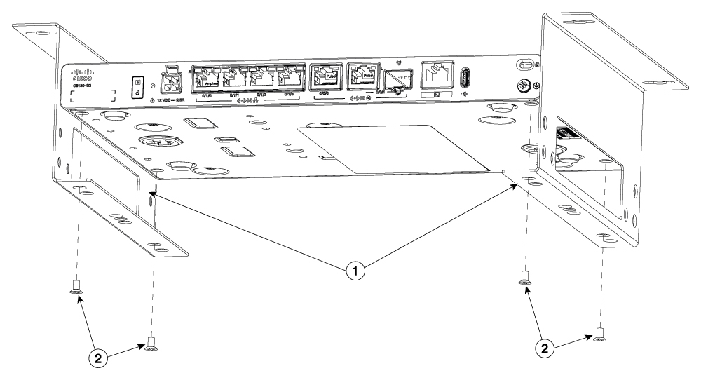
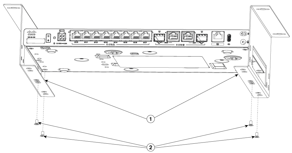
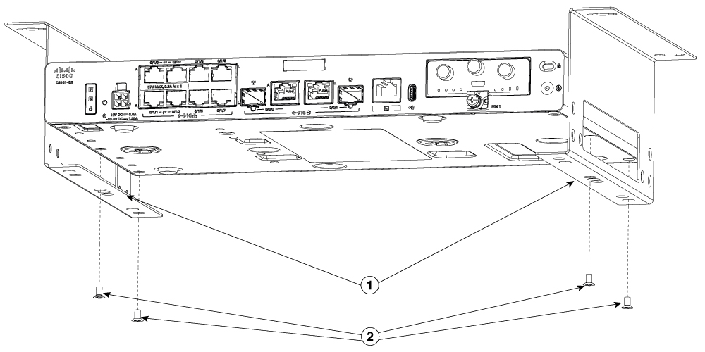
Align the brackets to the indicated screw holes of the chassis.

Example:

Figure 17. Under desk mounting brackets installation for C8130-G2 and C8131-G2

1

Under desk mounting brackets

2

Screws

Example:

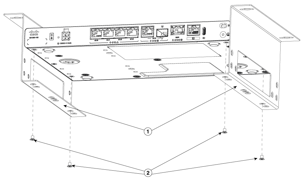
Figure 18. Under desk mounting brackets installation for C8140-G2

1

Under desk mounting brackets

2

Screws

Example:

Figure 19. Under desk mounting brackets installation for C8151-G2 and C8161-G2

1

Under desk mounting brackets

2

Screws

Example:

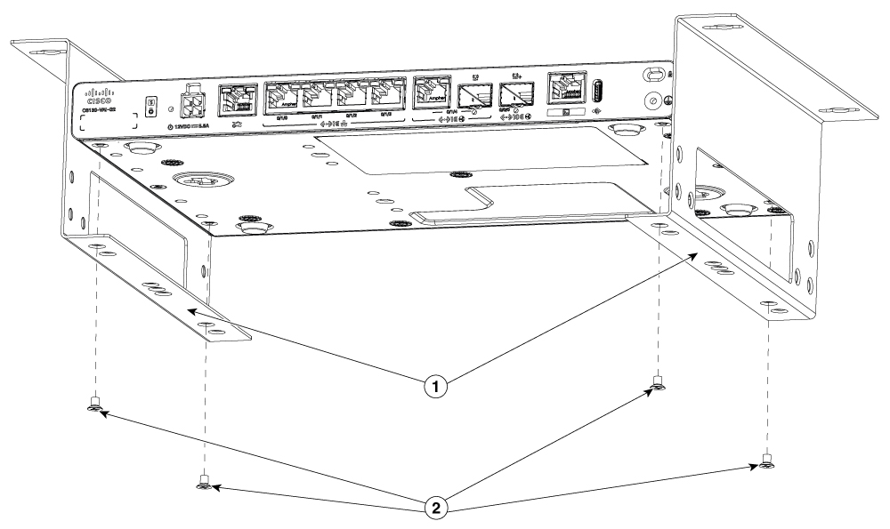
Figure 20. Under desk mounting brackets installation for C8130-VAI-G2 and C8130-VAP-G2

1

Under desk mounting brackets

2

Screws

Example:

Figure 21. Under desk mounting brackets installation for C8151-CVAI-G2 and C8151-CVAP-G2

1

Under desk mounting brackets

2

Screws

3.

Secure the under desk mounting brackets to the router using the screws. Ensure that all the screw fasteners on the installed components are securely tightened.

Example:

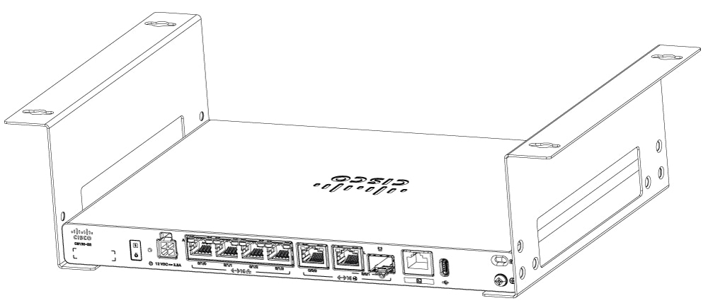
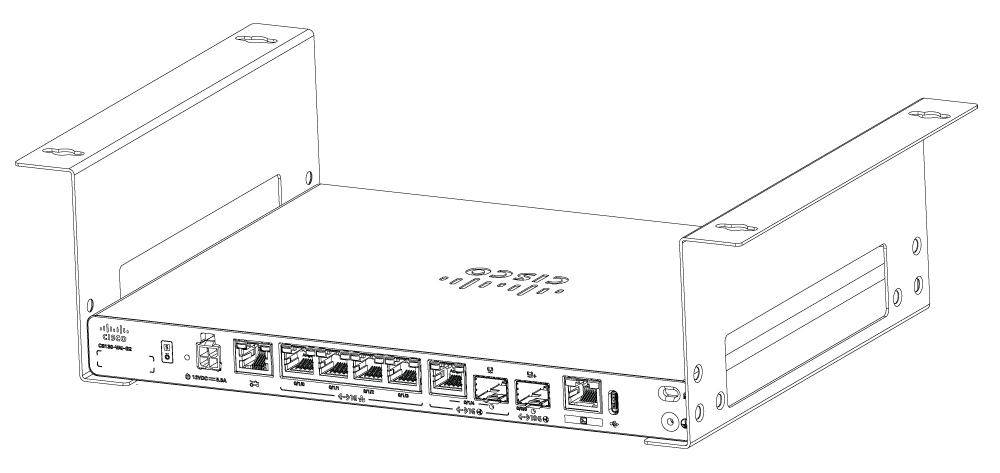
Figure 22. C8130-G2 and C8131-G2 with attached under desk mounting brackets

Example:

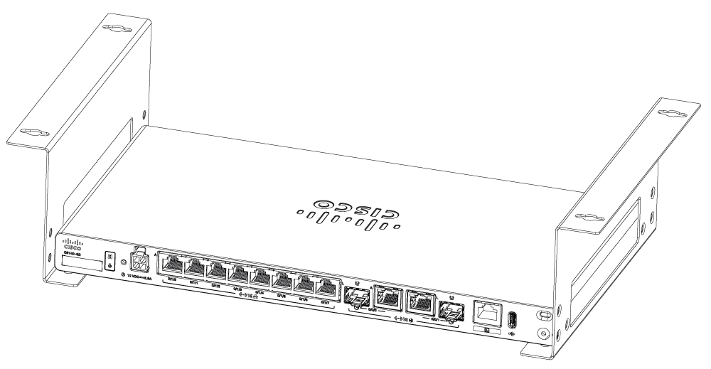
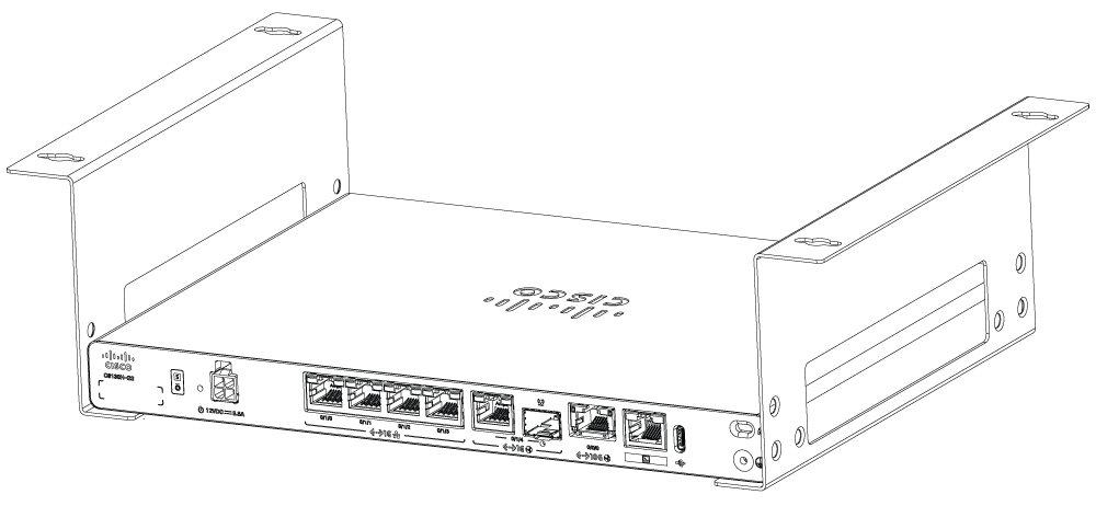
Figure 23. C8140-G2 with attached under desk mounting brackets

Example:

Figure 24. C8151-G2 and C8161-G2 with attached under desk mounting brackets

Example:

Figure 25. C8130-VAI-G2 and C8130-VAP-G2 with attached under desk mounting brackets

Example:

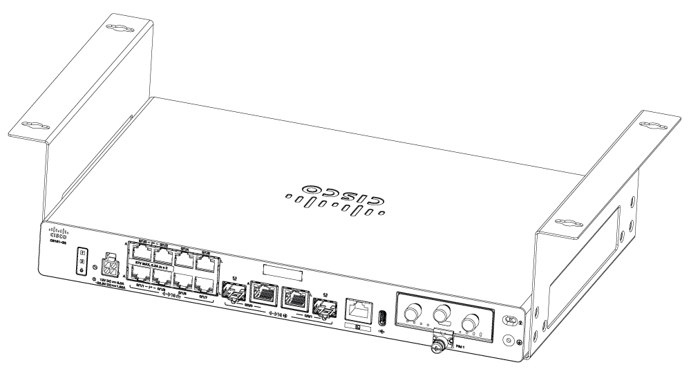
Figure 26. C8151-CVAI-G2 and C8151-CVAP-G2 with attached under desk mounting brackets
4.

After the bracket is attached, drill a 2mm hole under the desk and insert the wooden screws. Mount the router under the desk or shelf using the pan-head wood screws.

Example:

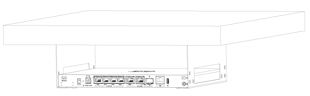
Figure 27. Mounting C8130-G2 and C8131-G2 under a shelf
Figure 28. Mounting C8140-G2 under a shelf
Figure 29. Mounting C8151-G2 and C8161-G2 under a shelf
Figure 30. Mounting C8130-VAI-G2 and C8130-VAP-G2 under a shelf
Figure 31. Mounting C8151-CVAI-G2 and C8151-CVAP-G2 under a shelf
Figure 32. Pan-head wood screws

Wall mount

There are two ways to mount a router on the wall, using Keyhole slots and DIN rail brackets.

Warning

Statement 1094—Read Wall-Mounting Instructions Before Installation

Read the wall-mounting instructions carefully before beginning installation. Failure to use the correct hardware or to follow the correct procedures could result in a hazardous situation to people and damage to the system.

Note

The recommended clearance when a router is horizontally mounted is 1.5 inches on both sides for clearance and 1.75 inches on top. I/O side clearance is needed as it is required to access the cable connections. Clearance is not required on the backside (opposite side from I/O face) unless mounting on a DIN rail. Clearance is required to attach and mount the DIN rail bracket.


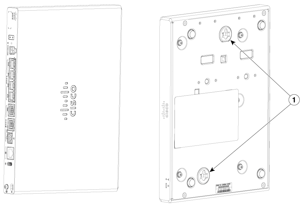
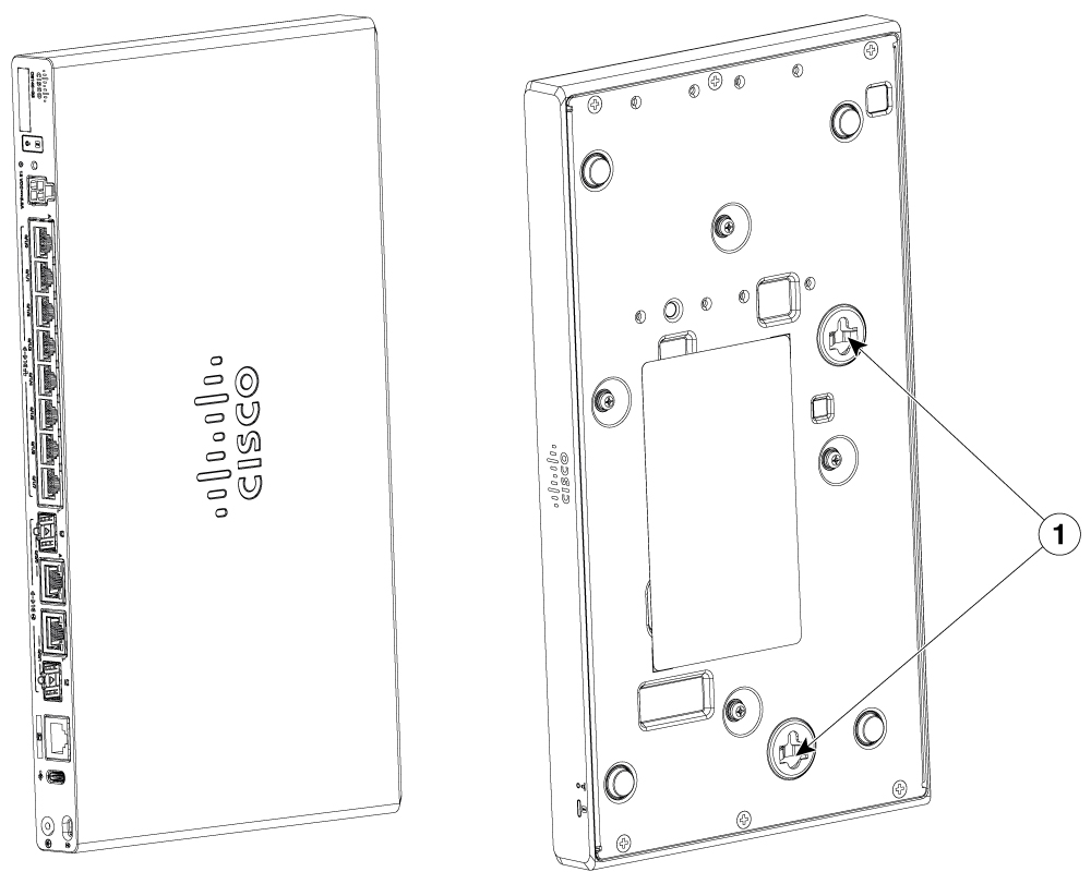
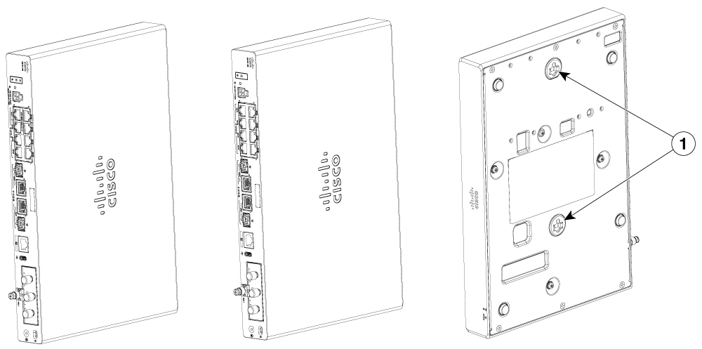
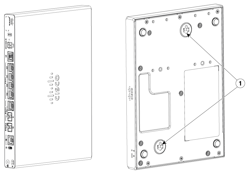
Wall mount using Keyhole Slots

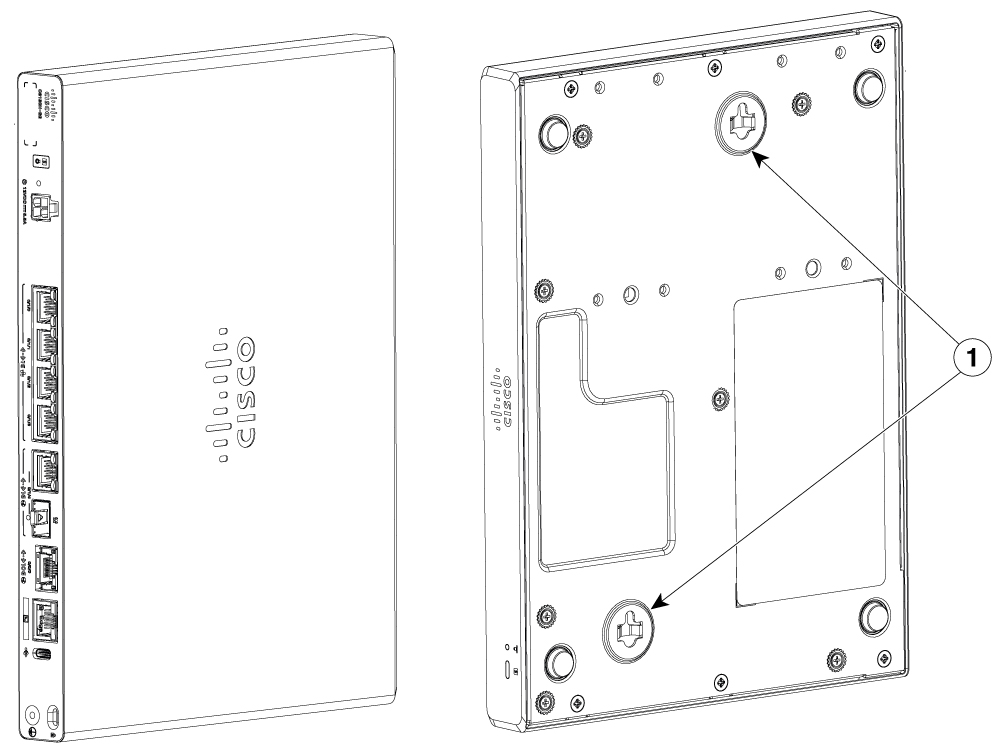
The Cisco 8100 Series Secure Routers have keyhole slots at the bottom of the chassis for mounting on a wall or any vertical surface.

Note

When choosing a location for wall mounting the router, consider cable limitations and wall structure.

Note

Route the cables so that they do not put a strain on the connectors or mounting hardware.

Procedure

1.

Measure the distance between both the keyhole slots and mark them onto the wall.

2.

Drill holes into the wall as per the markings you took in Step 1, and insert the screws in it.

To attach a router to the wall stud, each bracket should have one number 10 wood screw (pan-head) with number 10 washers, or two number 10 washer-head screws. The screws must be long enough to penetrate at least 1.5 inches (38.1 mm) into the supporting wood or metal wall stud.

For hollow-wall mounting, each bracket requires two wall anchors with washers. Wall anchors and washers must be size number 6 (pan-head).

3.

Place the router onto the screws and slide the router to lock it into place.

Example:

Figure 33. Wall mount using keyhole slots for C8130-G2 and C8131-G2

1

Keyhole slots

Horizontal spacing: 1.693 in(43.00 mm)

Vertical spacing: 8.113 in(206.07 mm)

Figure 34. Wall mount using keyhole slots for C8140-G2

1

Keyhole slots

Horizontal spacing: 1.330 in(33.78 mm)

Vertical spacing: 6.500 in(165.10 mm)

Figure 35. Wall mount using keyhole slots for C8151-G2 and C8161-G2

1

Keyhole slots

Key-hole slots spacing: 7.250 in(184.15 mm)

Figure 36. Wall mount using keyhole slots for C8130-VAI-G2 and C8130-VAP-G2

1

Keyhole slots

Horizontal spacing: 2.38 in(60.37 mm)

Vertical spacing: 8.035 in(204.08 mm)

Figure 37. Wall mount using keyhole slots for C8151-CVAI-G2 and C8151-CVAP-G2

1

Keyhole slots

Horizontal spacing: 2.38 in(60.37 mm)

Vertical spacing: 8.035 in(204.08 mm)


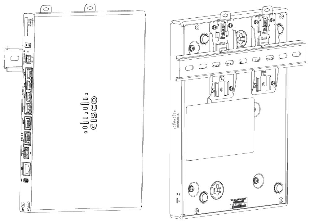
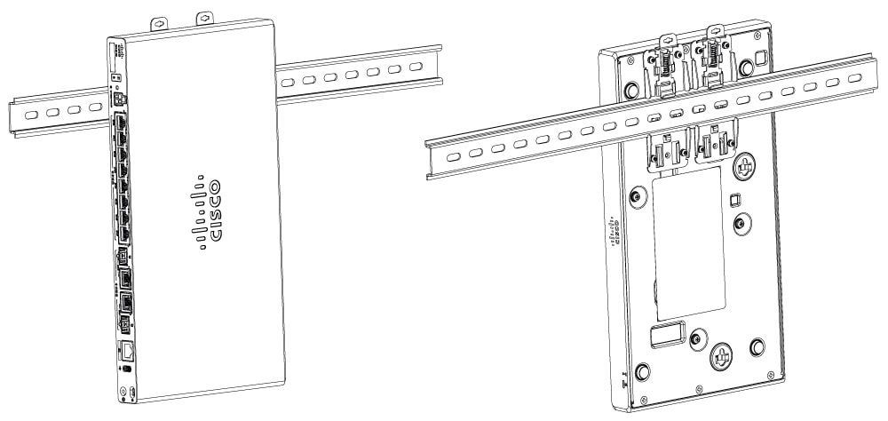
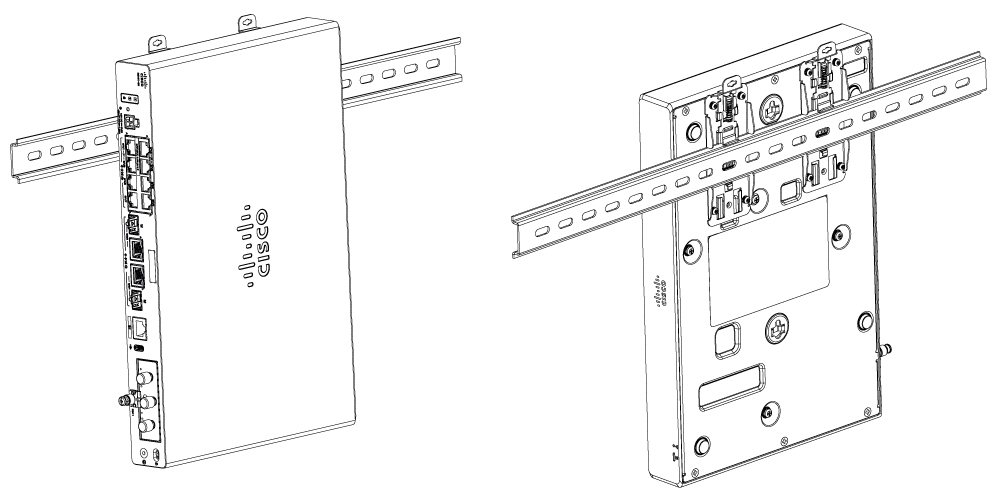
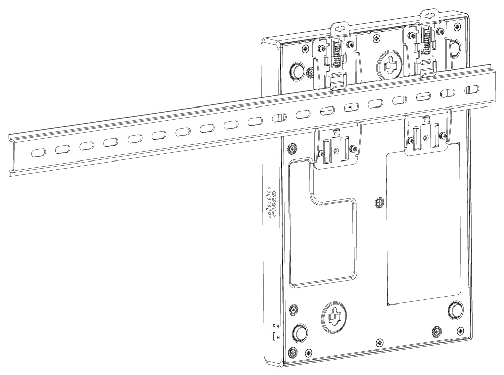
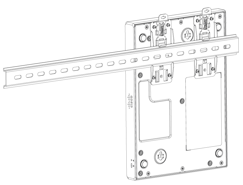
Wall mount using DIN rail brackets

The router is shipped with DIN rail brackets that are to be secured on the bottom side of the chassis. Your chassis installation must allow unrestricted airflow for chassis cooling.

Procedure

1.

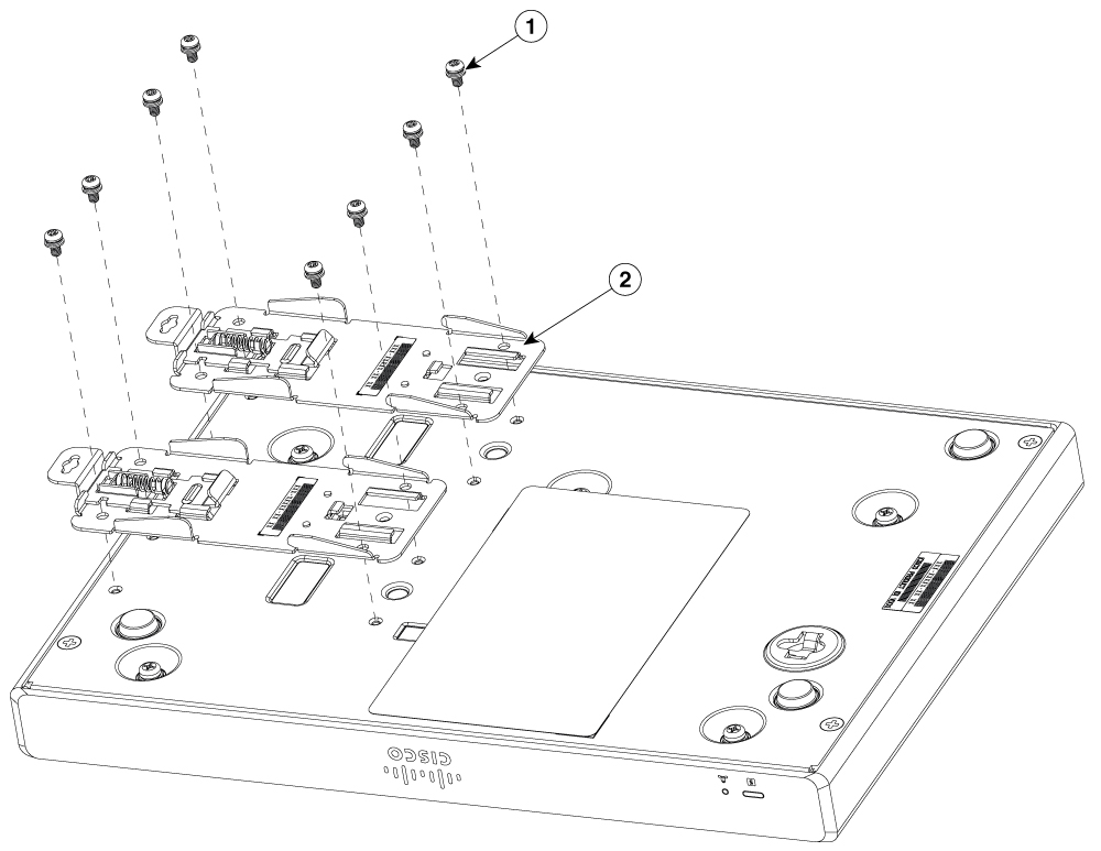
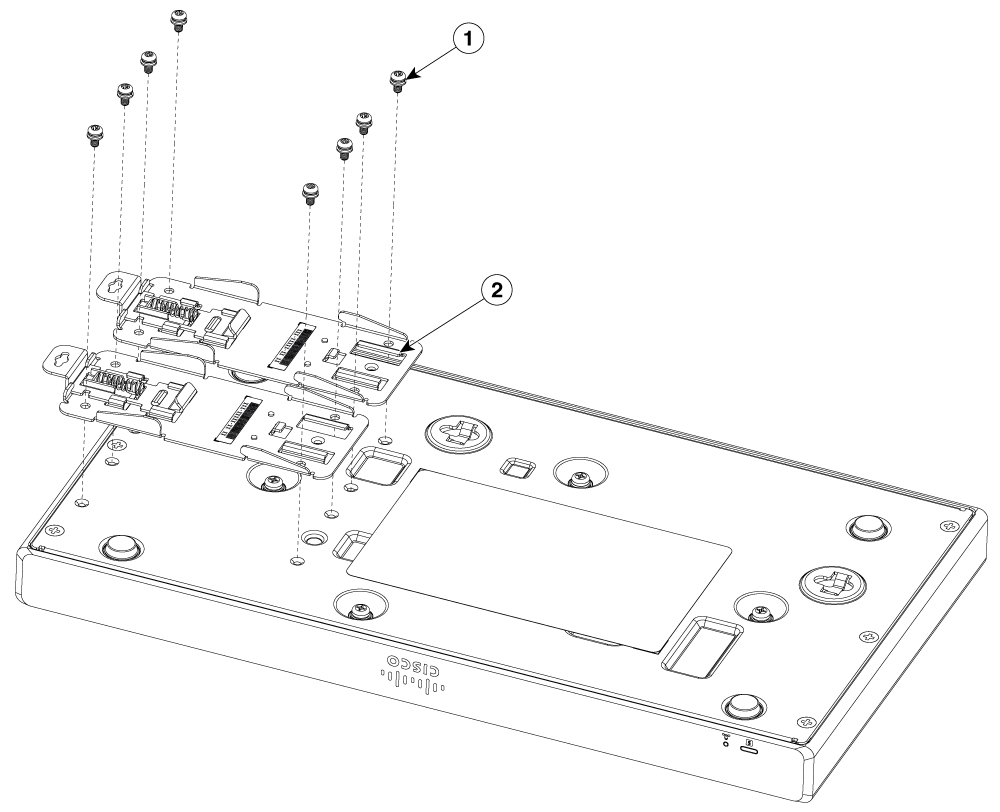
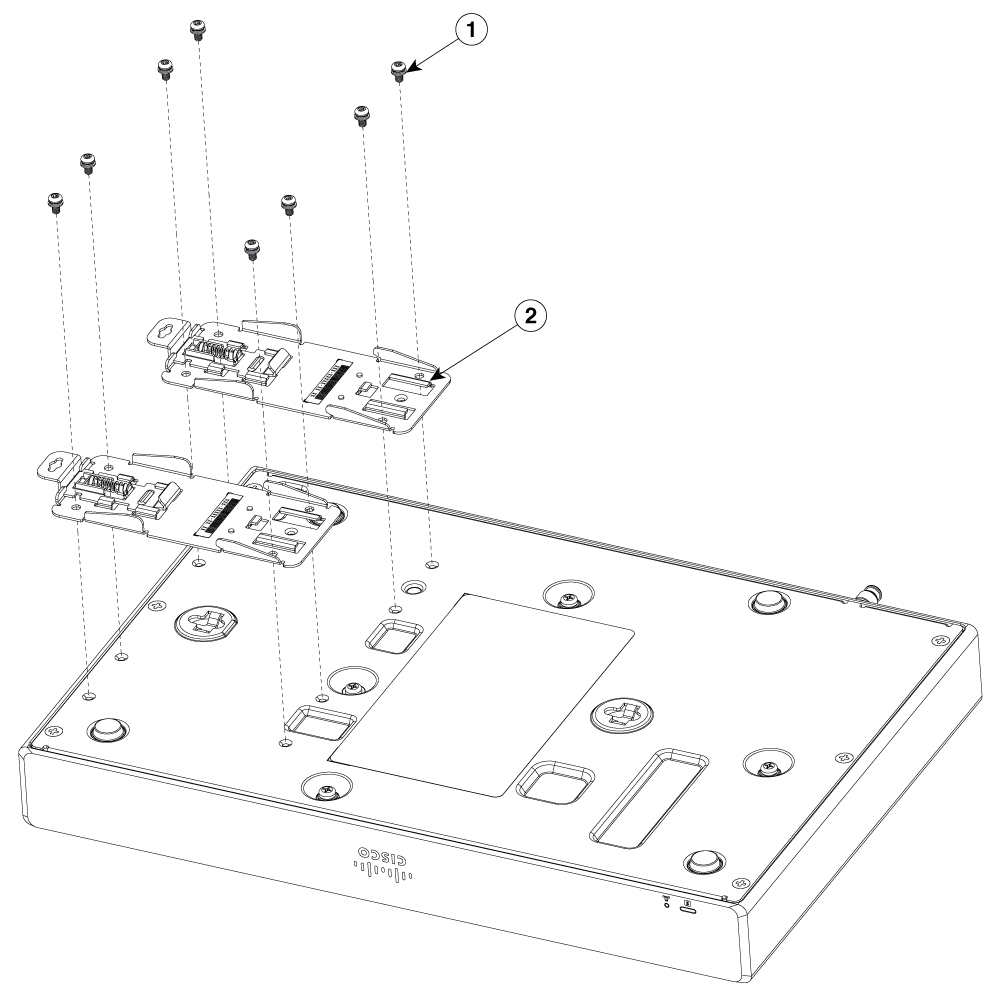
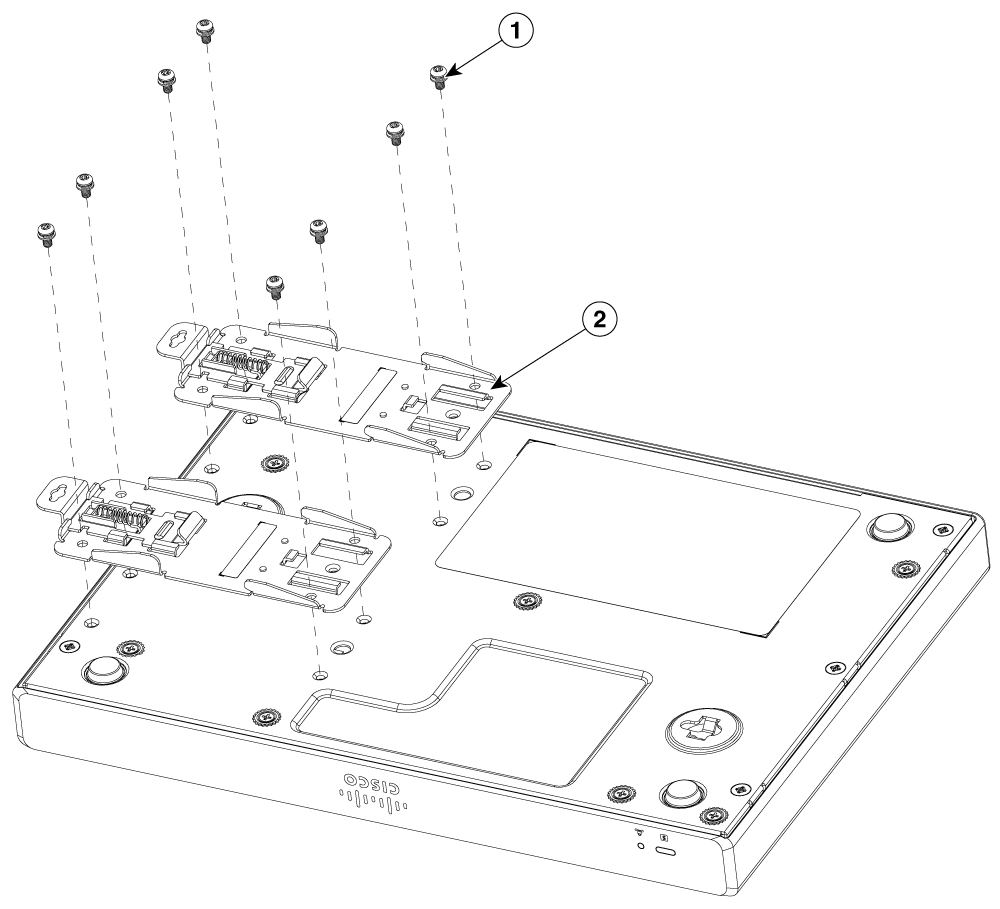
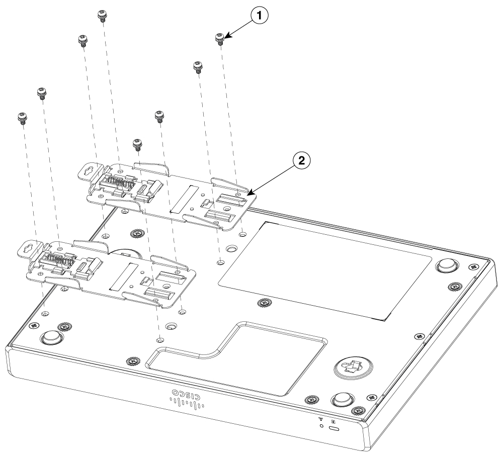
Align the din rail brackets to the holes indicated in the listed figure.To attach the DIN rail brackets to the router chassis, use the PHMS screws and the plastic spacers provided for each bracket.

Example:

Figure 38. DIN rail bracket installation for C8130-G2 and C8131-G2

1

PHMS screws

2

DIN rail brackets

Example:

Figure 39. DIN rail bracket installation for C8140-G2

1

PHMS screws

2

DIN rail brackets

Example:

Figure 40. DIN rail bracket installation for C8151-G2 and C8161-G2

1

PHMS screws

2

DIN rail brackets

Example:

Figure 41. DIN rail bracket installation for C8130-VAI-G2 and C8130-VAP-G2

1

PHMS screws

2

DIN rail brackets

Example:

Figure 42. DIN rail bracket installation for C8151-CVAI-G2 and C8151-CVAP-G2

1

PHMS screws

2

DIN rail brackets

2.

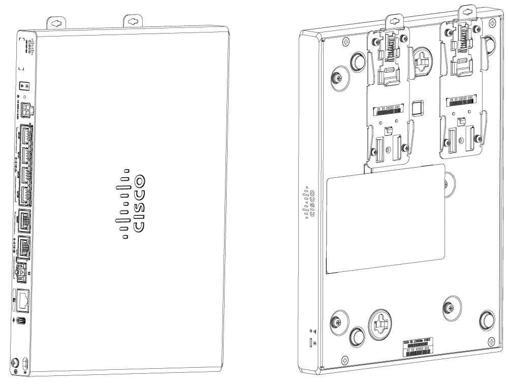
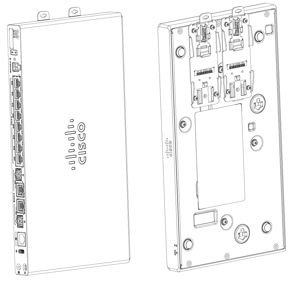
Secure the din rail brackets to the router using the PHMS screws and the plastic spacers provided for each bracket.

Example:

Figure 43. C8130-G2 and C8131-G2 with attached DIN rail brackets
Figure 44. C8140-G2 with attached DIN rail brackets
Figure 45. C8151-G2 and C8161-G2 with attached DIN rail brackets
Figure 46. C8130-VAI-G2 and C8130-VAP-G2 with attached DIN rail brackets
Figure 47. C8151-CVAI-G2 and C8151-CVAP-G2 with attached DIN rail brackets
Note

Do not over-torque the screws. The recommended torque is 8 to 10 inch-lbf (0.9 to 1.1 N-m).

3.

Attach the brackets onto the DIN rail to clamp it together.

Example:

Figure 48. Mounting C8130-G2 and C8131-G2 using DIN rail brackets
Figure 49. Mounting C8140-G2 using DIN rail brackets
Figure 50. Mounting C8151-G2 and C8161-G2 using DIN rail brackets
Figure 51. Mounting C8130-VAI-G2 and C8130-VAP-G2 using DIN rail brackets
Figure 52. Mounting C8151-CVAI-G2 and C8151-CVAP-G2 using DIN rail brackets

Chassis grounding

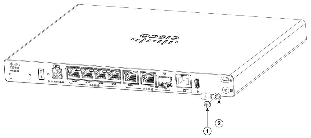
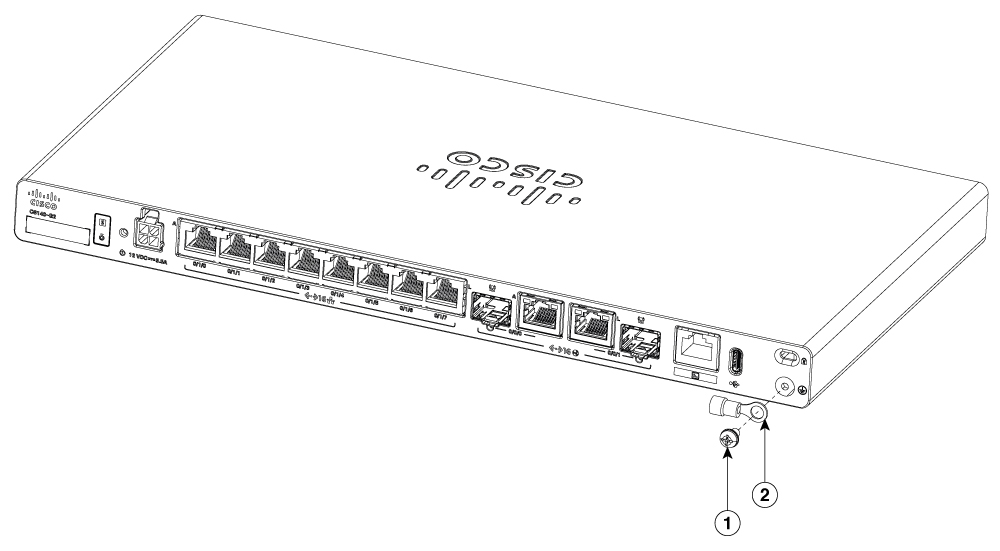
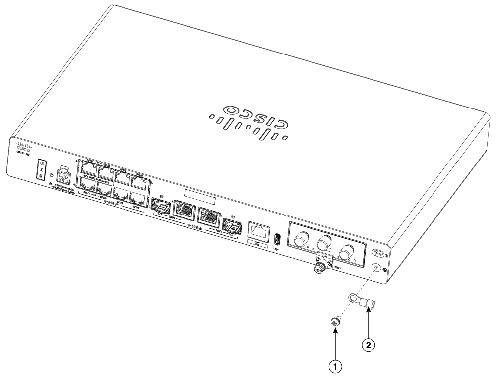
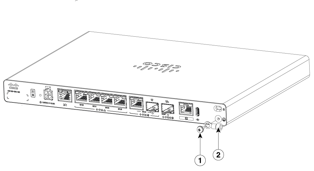
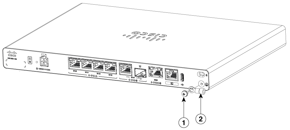
After you set up the router, connect the chassis to a reliable earth ground. The ground wire must be installed in accordance with local electrical safety standards. For grounding the chassis, use a copper wire of size of 14 AWG (2 mm²). These components are provided along with the router:

  1. Ground Lug

  2. UNC 6-32 screws which have a length of about 0.25 inches.

To install the ground connection for your router, perform these steps:

  1. Strip one end of the ground wire to the length approximately 0.75 inch (20 mm) for the ground lug.

  2. Crimp the ground wire to the ground lug using a crimp tool of the appropriate size.

  3. Attach the ground lug to the chassis as shown in the below figures. Tighten the screw; the recommended torque is 8 to 10 inch-lbf (0.9 to 1.1 N-m).

Figure 53. Chassis ground connection - C8130-G2 and C8131-G2

1

Screw (UNC 6-32)

2

Ground lug

Figure 54. Chassis ground connection - C8140-G2

1

Screw (UNC 6-32)

2

Ground lug

Figure 55. Chassis ground connection - C8151-G2 and C8161-G2

1

Screw (UNC 6-32)

2

Ground lug

Figure 56. Chassis ground connection - C8130-VAI-G2 and C8130-VAP-G2

1

Screw (UNC 6-32)

2

Ground lug

Figure 57. Chassis ground connection - C8151-CVAI-G2 and C8151-CVAP-G2

1

Screw (UNC 6-32)

2

Ground lug


Ground connection warnings

Details of ground connection warnings:

Warning

Statement 1101—Connected To Grounded Outlet

In the Scandinavian countries (Denmark, Finland, Iceland, Norway, and Sweden) the appliance must be connected to a grounded outlet.


Optical connection SFP warnings

Details of optical connection warnings:

Warning

Statement 1051—Laser Radiation

Invisible laser radiation may be emitted from disconnected fibers or connectors. Do not stare into beams or view directly with optical instruments.