Hardware Installation Guide for the Cisco 8100 Series Secure Routers

PDF

Install a Pluggable Interface Module

Want to summarize with AI?

Log in

Details installing a pluggable interface module, including antenna insertion, connector specifications for embedded 5G devices, RF band mapping, and micro SIM integration, ensuring comprehensive module setup and connectivity.


Before you begin

Warning

Statement 1255—Laser Compliance Statement

Pluggable optical modules comply with IEC 60825-1 Ed. 3 and 21 CFR 1040.10 and 1040.11 with or without exception for conformance with IEC 60825-1 Ed. 3 as described in Laser Notice No. 56, dated May 8, 2019.

Procedure

1.

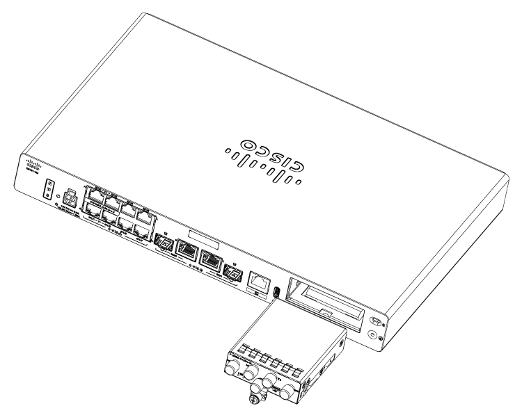
Insert and then gently push the Cellular pluggable into the pluggable slot of C8151-G2 or C8161-G2 until firmly fixed.

Example:

Figure 1. Pluggable Interface Module installation for C8151-G2 and C8161-G2
2.

Tighten the screw, the recommended torque is 10-12 in-lb.

Example:

Figure 2. C8151-G2 and C8161-G2 with attached Pluggable Interface Module
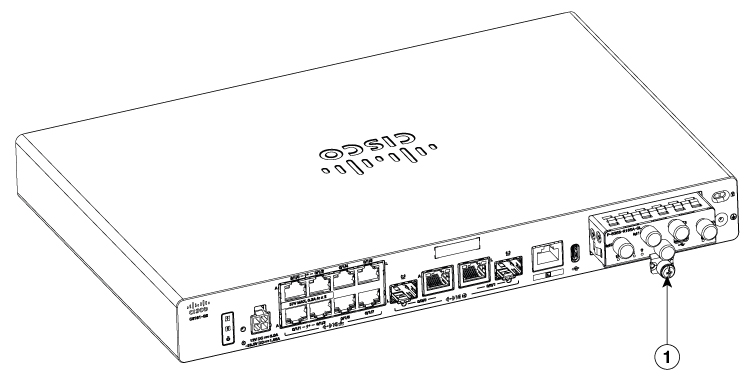
1

Screw

Figure 3. LTE Pluggable Interface Module - P-LTEA7-EAL
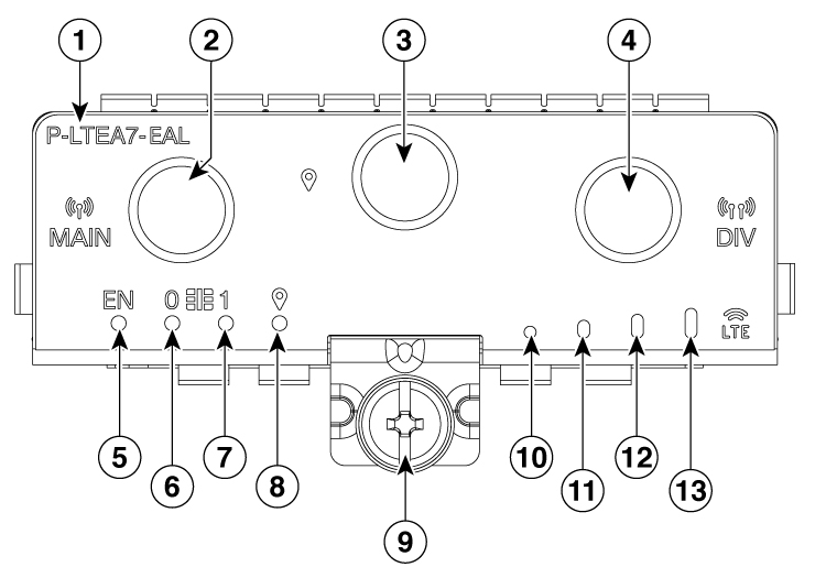
1

Product Identification Number (PID)

2

Main antenna connector (SMA)

3

GPS connector (SMA)

4

Diversity antenna connector (SMA)

5

Enable LED

6

SIM 0 LED

7

SIM 1 LED

8

GPS LED

9

M3.5 thumbscrew

10

RSSI 0

11

RSSI 1

12

RSSI 2

13

RSSI 3

Figure 4. LTE Pluggable Interface Module - P-LTEA7-JP
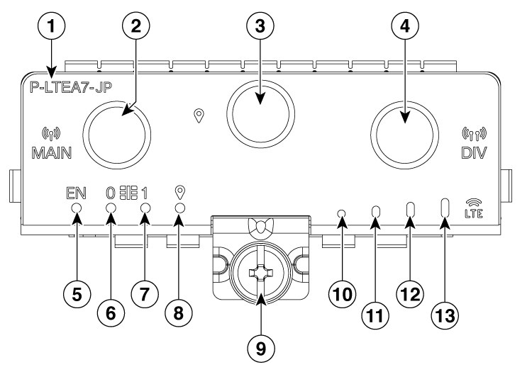
1

Product Identification Number (PID)

2

Main antenna connector (SMA)

3

GPS connector (SMA)

4

Diversity antenna connector (SMA)

5

Enable LED

6

SIM 0 LED

7

SIM 1 LED

8

GPS LED

9

M3.5 thumbscrew

10

RSSI 0

11

RSSI 1

12

RSSI 2

13

RSSI 3

Figure 5. LTE Pluggable Interface Module - P-LTEA7-NA
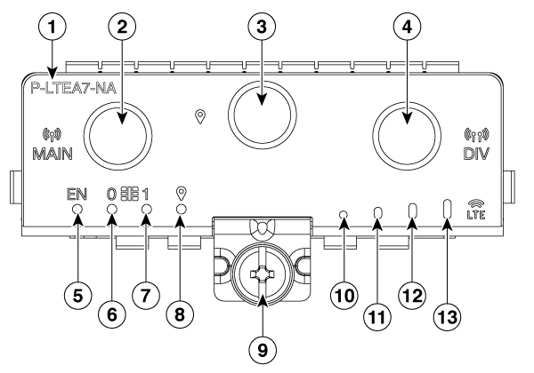
1

PID

2

Main antenna slot (SMA)

3

GPS (SMA)

4

Diversity antenna slot (SMA)

5

Enable LED

6

SIM 0 LED

7

SIM 1 LED

8

GPS LED

9

M3.5 thumbscrew

10

RSSI 0

11

RSSI 1

12

RSSI 2

13

RSSI 3

Figure 6. 5G Pluggable Interface Module - P-5GS6-R16SA-GL
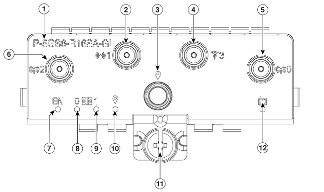
1

PID

2

Main antenna slot 1 (SMA)

3

GPS (SMA)

4

Antenna slot 3 (SMA, reception only)

5

Antenna slot 0 (SMA)

6

Antenna slot 2 (SMA)

7

Enable LED

8

SIM 0 LED

9

SIM 1 LED

10

GPS LED

11

M3.5 thumbscrew

12

Service LED

Insert antenna into the Pluggable Interface Module

To insert the antenna in the Pluggable Interface Module, perform these steps:

Procedure

1.

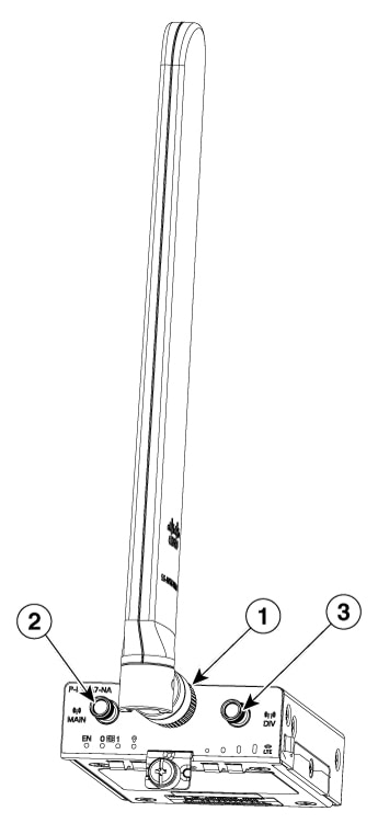
Insert and tighten antennas in the antenna slots as per the sequence mentioned in the figure.

Example:

Figure 7. Attaching the antennas
Note

You need to install antennas as per the sequence to get enough space to tighten antennas in all the antenna slots.

2.

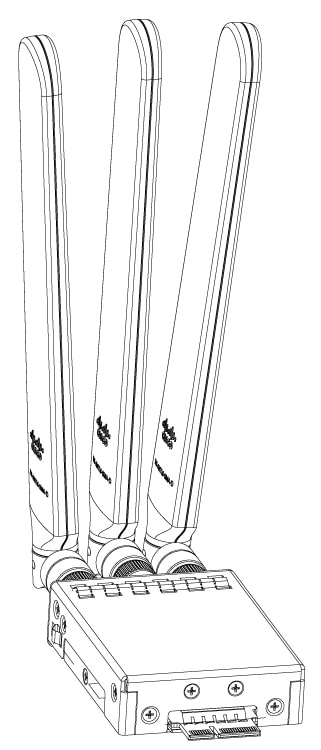
After installing the antennas, adjust the antenna orientation by spacing out each of them equally until they are spread out. This is significant as it helps in getting higher RF performance.

Example:


Antenna connector details for embedded 5G devices

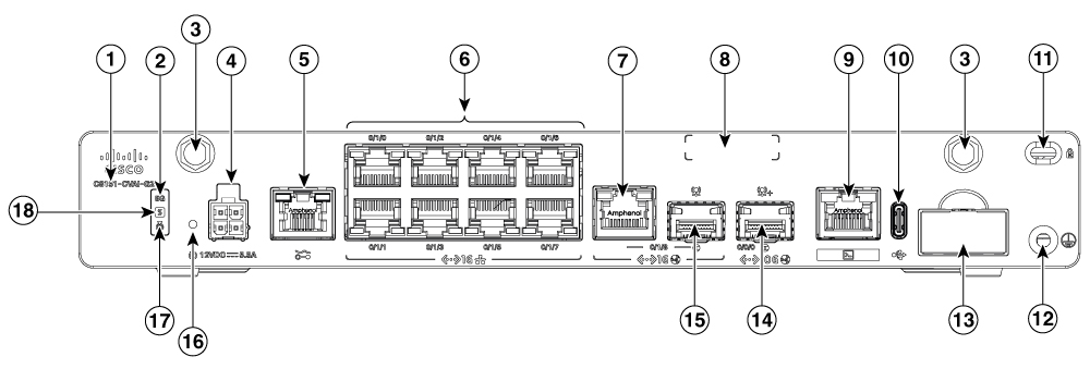
The antenna SMA connector (labeled as #3) enables connection to an external antenna, optimizing 5G performance on the C8151-CVAI-G2 and C8151-CVAP-G2 devices, as shown in the image.

Figure 8. C8151-CVAI-G2 and C8151-CVAP-G2 - Front view

RF band mapping for antenna ports

This table lists the RF band mapping for antenna ports.

Table 1. RF band mapping for antenna ports for P-5GS6-R16SA-GL
Radio Access Technology (RAT)

Bands

Tx antennas

Rx antennas

GNSS antenna

-

-

Default

Alternate Path

ANT0

ANT1

ANT2

ANT3

GPS

5GNR Sub-6G

29

-

-

Y

-

Y

-

-

38, 41

ANT2

ANT0

Y

Y

Y

Y

-

48

ANT3

ANT1

Y

Y

Y

Y

-

75, 76

-

-

Y

Y

Y

Y

-

77, 78

ANT3

ANT1

ANT2

Y

Y

Y

Y

-

79

ANT3

ANT1

Y

Y

Y

Y

-

LB LTE/

5GNR Sub-6G

5, 8, 12, 13, 14, 17, 18, 19, 20, 26, 28, 71

ANT0

-

Y

-

Y

-

-

MB/HB LTE/ 5G NR Sub-6G

1, 2, 3, 4, 7, 25, 30, 39, 40, 66, 70

ANT0

-

Y

Y

Y

Y

-

LTE

29

-

-

Y

-

-

Y

-

34

ANT0

-

Y

-

Y

-

-

46

-

-

Y

-

-

Y

-

32

-

-

Y

Y

Y

Y

-

38

ANT0

-

Y

Y

Y

Y

-

41

ANT0

ANT2

Y

Y

Y

Y

-

42, 43, 48

ANT3

ANT1

Y

Y

Y

Y

-

WCDMA

1, 2, 4, 5, 8, 19

ANT0

-

Y

-

Y

-

-

GNSS

-

-

-

-

-

-

-

L1


Insert Micro-SIM into a Pluggable Interface Module

This section describes how to insert a Micro-SIM card into a Cellular Pluggable Module. To insert the Micro-SIM cards into a Cellular Pluggable Module, follow these instructions:

Procedure

1.

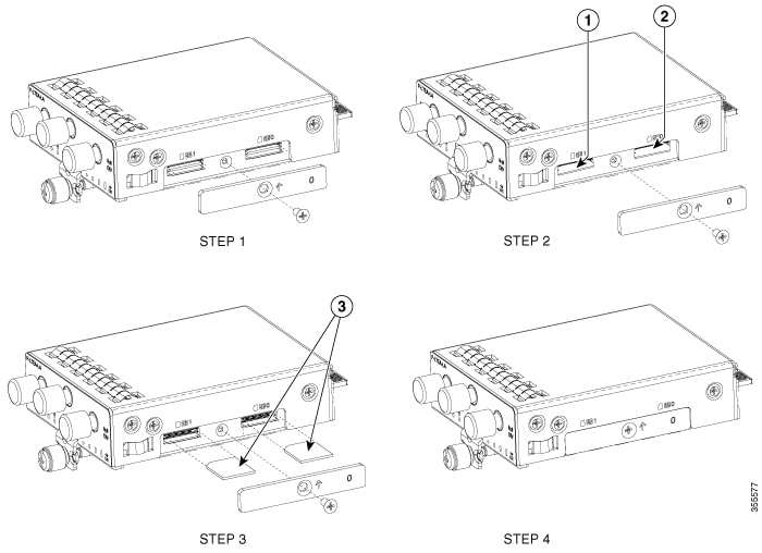
Place the pluggable module on its bottom side, remove the SIM door screw, use a #1 Philips screwdriver for removing the screws, and then carefully remove the Micro-SIM cover from the pluggable module.

Note

Ensure to use the correct tool for removing the Micro-SIM door.

2.

Slot 1 and slot 0 are the Micro-SIM slots.

Caution

Do not touch any part of the exposed PCB circuit area when the Micro-SIM cover is removed.

3.

Install SIM 0 and SIM 1 in their respective slots. SIM 0 or SIM 1 is marked on the pluggable interface module above the Micro-SIM cover. The SIM icons show the correct orientation required to install the SIM into each respective connector (SIM connectors are a push-push type). To install, insert the SIM card in the connector until you feel it click, then let go and the SIM is locked to the connector. To remove the SIM card, depress the SIM in the connector slot again until you feel the same click and let it go; the SIM connector should eject part way out of the connector. The SIM card can then be grabbed and removed. Secure the Micro-SIM cover with a screw, use a number 1 Philips screwdriver to secure the screw on the Micro-SIM cover. The recommended torque is 2.8 - 3.8 inch LBF.

Note

We recommend using industrial-grade SIM cards.

4.

You have now successfully inserted the Micro-SIM cards into the Cellular pluggable module. The marking on the Mirco-SIM door should align with Micro-SIM 0 on the pluggable module with the arrow pointing upward.

Example:

Figure 9. Insert the Micro-SIM cards