Hardware Installation Guide for the Cisco 8100 Series Secure Routers

PDF

Hardware Installation Guide for the Cisco 8100 Series Secure Routers

Connect the power cable

Want to summarize with AI?

Log in

Explains power and data connection procedures, outlining how to connect the power cable, set up console access across major operating systems, connect WAN and LAN interfaces, and follow comprehensive cabling guidelines and precautionary measures.


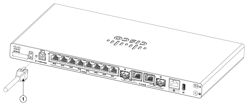
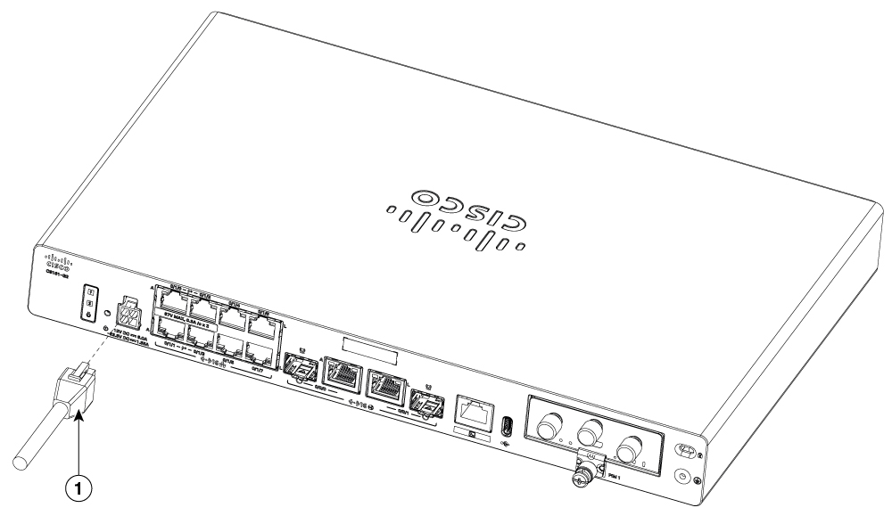
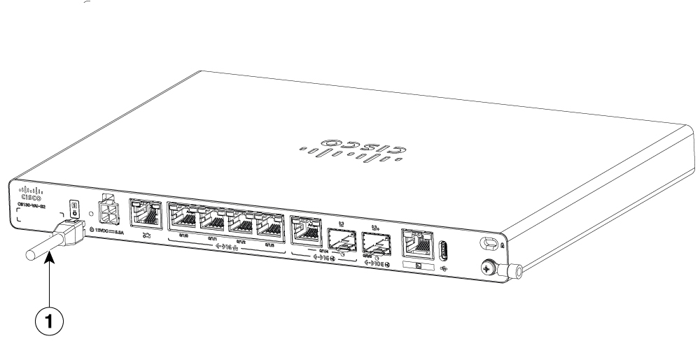
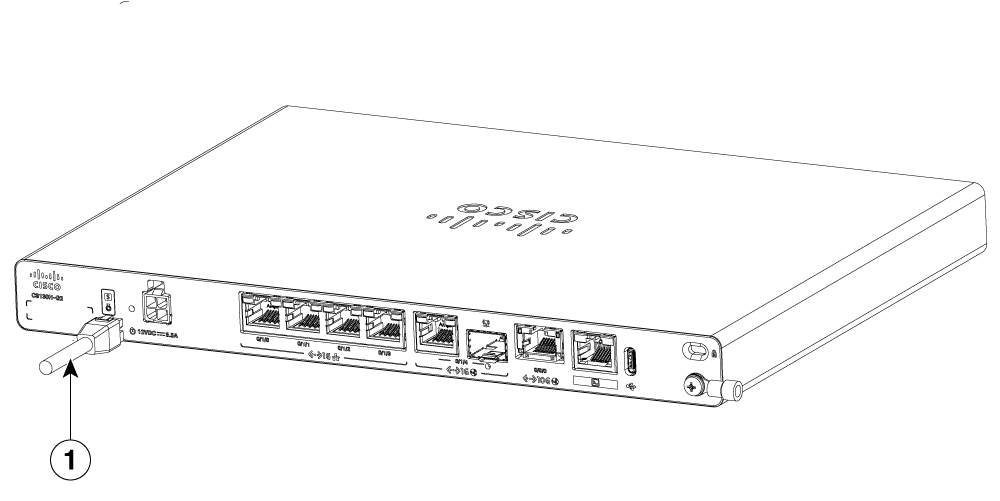
Power supply of the Cisco 8100 Series Secure Routers is an external AC to DC power adapter. The external DC power connector plugs into the router's 4 points power connector.

The router does not have a power button. Refer to the below listed details to power on/off the router:

  • To power on the router – you can locate the power cable and connect it to a power source.

  • To power off the router – unplug the power cord from the back of the router or gently pull the power cable from the router or the wall outlet.
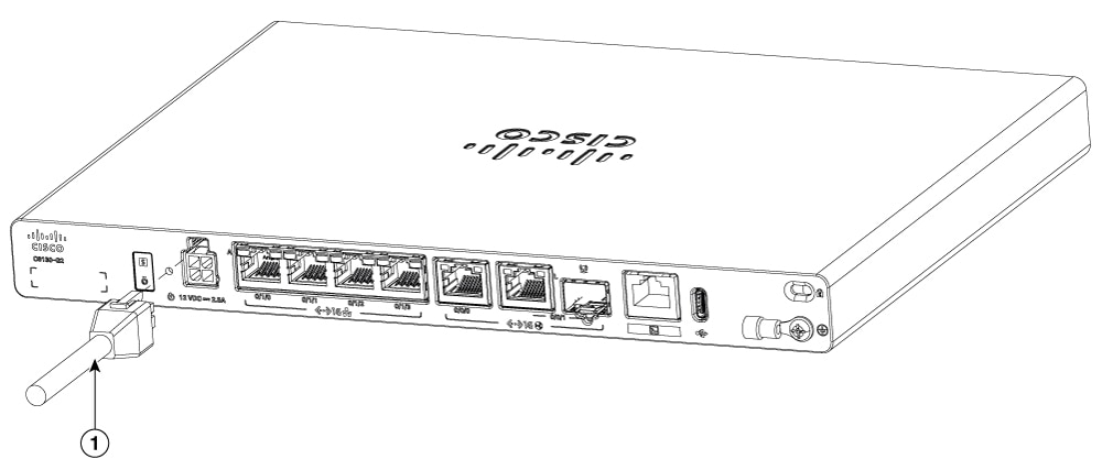
Figure 1. Power cable - C8130-G2 and C8131-G2

1

Power cable

Figure 2. Power cable - C8140-G2

1

Power cable

Figure 3. Power cable - C8151-G2 and C8161-G2

1

Power cable

Figure 4. Power cable - C8130-VAI-G2 and C8130-VAP-G2

1

Power cable

Figure 5. Power cable - C8151-CVAI-G2 and C8151-CVAP-G2

1

Power cable


Connect the router to a console

The Cisco 8100 Series Secure Routers contains a RJ45 console port. This port provides administrative access to the router through a console terminal or a PC.

Use the RJ45 console port on the router to access the Cisco Internetwork Operating System (IOS XE) command line interface (CLI) on the router and perform configuration tasks. A terminal emulation program is required to establish communication between the router and a PC.

To configure the router through the CLI, you must establish a connection between the router console port and either a PC or a terminal.

Use the cables and adapters as listed in this table to establish a local or remote connection.

Table 1. Local and remote connections

Port type

Cable

Action

Serial (RJ45)

RJ45 serial console cable

Connecting to the serial port with terminal emulation program.


Connect to the serial port with Microsoft Windows

This procedure describes how to connect a Microsoft Window USB port to a console port.

Before you begin

To establish a physical connectivity between the router and a PC, you need to install a Microsoft Windows USB.

Procedure

1.

Connect the end of the console cable with the RJ45 connector to the light blue console port on the router.

2.

Connect the end of the cable with the DB-9 connector (or USB Type-A) to the terminal or PC. If your terminal or PC has a console port that does not accommodate a DB-9 connector, you must provide an appropriate adapter for that port.

3.

Start a terminal emulator application to communicate with the router. Configure the software with these parameters:

  • 9600 baud

  • 8 data bits

  • no parity

  • 1 stop bit

  • no flow control


Connect to the console port with Mac OS X

This procedure describes how to connect a Mac OS X system USB port to the console using the built in OS X Terminal utility.

Procedure

1.

Use the Finder to go to Applications > Utilities > Terminal.

2.

Connect the OS X USB port to the router.

3.

Enter the commands to find the OS X USB port number.

Example:


macbook:user$ cd /dev
macbook:user$ ls -ltr /dev/*usb*
crw-rw-rw-  1 root    wheel       9,  66 Apr  1 16:46 tty.usbmodem1a21 DT-macbook:dev user$
4.

Connect to the USB port with the listed command followed by the router USB port speed.

Example:


macbook:user$ screen /dev/tty.usbmodem1a21 9600

To disconnect the OS X USB console from the Terminal window

Enter Ctrl-a followed by Ctrl-\


Connect to the console port with Linux

This procedure shows how to connect a Linux system USB port to the console using the built in Linux terminal utility.

Procedure

1.

Open the Linux terminal window.

2.

Connect the Linux USB port to the router.

3.

Enter the following commands to find the Linux USB port number.

Example:


root@usb-suse# cd /dev
root@usb-suse /dev# ls -ltr *ACM*
crw-r--r--    1 root     root     188,   0 Jan 14 18:02 ttyACM0
root@usb-suse /dev#
4.

Connect to the USB port with the following command followed by the router USB port speed.

Example:


root@usb-suse /dev# screen /dev/ttyACM0 9600
Note

To disconnect the Linux USB console from the terminal window:

Enter Ctrl-a followed by : then quit.


Connect WAN and LAN interfaces

This section describes how to connect WAN and LAN interface cables.


Ports and cabling

This section summarizes typical WAN and LAN connections for Cisco 8100 Series Secure Routers. The connections summarized here are described in detail in the Cisco Modular Access Router Cable Specifications document on cisco.com.

Table 2. WAN and LAN connections

Port

Port Type

Connection

Cable

Ethernet

RJ45

Ethernet hub or Ethernet switch

Category 5 or higher Ethernet

Gigabit Ethernet SFP, optical

LC

1000BASE-SX, -LX, -LH, -ZX, -CWDM

Optical fiber as specified on applicable data sheet

Gigabit Ethernet SFP, copper

RJ45

1000BASE-T

Category 5, 5e, 6 UTP

XGSPON/10GBASE-T

LC

SFP-10G-ONT20-I, SFP-10G-T-X

Optical fiber as specified on applicable data sheet

Note

The SFP slot supports pluggables compliant with 400KHz I2C clock speed (Fast Mode). Pluggables that operate only at 100KHz I2C clock speed (Standard Mode), such as certain v1 GLC-EX-SMD and GLC-ZX-SMD models, are not supported.


Connection procedures and precautions

After you have installed the router chassis, perform these steps to connect the WAN and LAN interfaces:

Procedure

1.

Connect each WAN and LAN cable to the appropriate ports on the chassis.

2.

Position the cables carefully so that you do not strain the connectors.

3.

Organize cables in bundles so that cables do not intertwine.

4.

Inspect the cables to make sure that the routing and bend radius is satisfactory. If necessary, reposition the cables.

5.

Install cable ties in accordance with site requirements.