Dynamic On-Demand Tunnels

Feature history for dynamic on-demand tunnels

Table 1. Feature History Table

Feature Name

Release Number

Description

Dynamic On-Demand Tunnels

Cisco IOS XE Catalyst SD-WAN Release 17.3.1a

Cisco SD-WAN Release 20.3.1

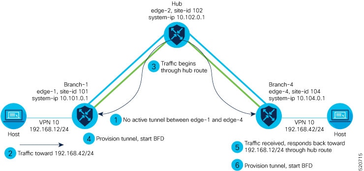
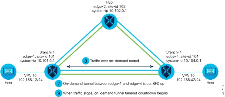
This feature enables you to configure an inactive state for tunnels between edge devices. This configuration reduces performance demands on devices and decreases network traffic.

Dynamic On-Demand Tunnels with Transport Gateways

Cisco IOS XE Catalyst SD-WAN Release 17.12.1a

Cisco Catalyst SD-WAN Manager Release 20.12.1

A transport gateway can serve as the hub between two spoke devices. It provides the backup route that is necessary for spoke-to-spoke on-demand tunnels to operate.

Using a transport gateway as the hub simplifies the process of enabling on-demand tunnels. This method does not require any changes to control policy on Cisco SD-WAN Controllers.

Dynamic on-demand tunnels

A Cisco Catalyst SD-WAN on-demand tunnel is a network feature that:

  • automatically establishes secure tunnels between spoke devices when traffic starts,

  • uses a configurable inactivity timer to remove tunnels after traffic stops, and

  • conserves bandwidth and device performance when inactive.

On-demand tunnels enable efficient, temporary connections that optimize network resource usage.

Cisco Catalyst SD-WAN on-demand tunnels are triggered by device traffic and are removed after a set period of inactivity, ensuring inactive links do not consume bandwidth or affect performance.

How on-demand tunnels work

Summary

When you configure a site to use dynamic tunnels, the on-demand functionality is enabled. In this mode of operation, Cisco Catalyst SD-WAN edge routers do not bring up direct tunnels to other sites that are also enabled with on-demand functionality.

Cisco Catalyst SD-WAN selects one or more edge routers (typically centrally located routers) to act as backup forwarding node(s), providing a secondary path for traffic between two nodes. The backup node(s) are not enabled for on-demand. All on-demand sites form static tunnels with the backup node(s). The backup node(s) provide a static backup route for traffic between two nodes that have on-demand enabled.

The first packet of traffic between two nodes is routed through the static backup path, and triggers the on-demand tunnel to become active between the sites. The backup path continues to forward traffic until the direct path becomes active.

All on-demand sites learn the TLOCs and prefixes of all other on-demand remote sites. The prefixes also have a backup path set up through Cisco Catalyst SD-WAN Controller control policy. So in the control plane, the on-demand tunnel network has the same state as a full-mesh tunnel network, including a backup path.

The control plane downloads to the data plane, routes, with the backup path and remote TLOCs that represent a potential direct path between any two sites, but it does not set up a direct path tunnel to remote TLOCs.

All prefixes learned from remote sites must have a backup path. A less-specific aggregate route from a hub site is not a valid backup path. The specific prefix advertised from the remote branch must also be advertised as a backup from the hub.

If this specific prefix is missing as a backup, the on-demand tunnel setup will fail.

Therefore, the backup path must be a static tunnel that is always UP. This static tunnel should include both the specific prefixes from the remote branch and any necessary aggregate routes to ensure proper tunnel establishment and maintenance.

Traffic from either end of the on-demand tunnel triggers setting up the tunnel. This enables on-demand tunnels to accommodate network address translation (NAT) traversal.

The on-demand tunnel feature introduces two states for the on-demand branch site:

  • Inactive: The on-demand tunnel is not set up with the remote site. There is no active traffic to or from the remote site. Remote site TLOCs are inactive—no bidirectional forwarding detection (BFD) is set up, the prefix is installed with the inactive paths, and the backup path is set as the path to forward any traffic.

  • Active: The on-demand direct site-to-site tunnel is set up to the remote site. There is active traffic to or from the remote site. This state is identical to the case of a typical tunnel, where the remote TLOCs have BFD set up, and the prefix is installed with the direct path tunnel. In this state, tunnel activity is tracked. If there is no traffic for the “idle time” duration (default 10 minutes), the direct site-to-site tunnel is removed and the state changes to Inactive.

Workflow

Figure 1. Process of On-Demand Tunnel Establishment Between Two Edge Routers

The steps below demonstrate what occurs between two edge routers with an on-demand tunnel configured.

  1. There is no active tunnel between the two edge routers. edge-1 and edge-4 are in their inactive states.

  2. The host behind edge-1 initiates traffic toward the host behind edge-4.

  3. edge-1 forwards the traffic through the backup path using the hub or backup node to edge-4.

  4. edge-1 provisions the on-demand tunnel and begins bidirectional forwarding detection (BFD). edge-4 is now in its active state on edge-1.

  5. When edge-4 receives the return traffic for the host behind edge-1, it forwards the traffic through the backup path using the hub or backup node to edge-1.

  6. edge-4 provisions the on-demand tunnel and begins BFD. edge-1 is now in active state on edge-4.

  7. At this point, the on-demand tunnel between edge-1 and edge-4 is up, and BFD is up.

  8. Traffic between the two edge devices takes the direct route through the on-demand tunnel.

  9. Both edge-1 and edge-4 track the traffic activity on the on-demand tunnel in both directions.

    If there is no traffic for the idle timeout duration, the on-demand tunnel is deleted, and the edge-1 and edge-4 devices go back to the inactive state.

How on-demand tunnels work with a transport gateway

Summary

A transport gateway can serve as the hub between two spoke devices, providing the backup route that is necessary for spoke-to-spoke on-demand tunnels to operate. Using a transport gateway as the hub simplifies the process of enabling on-demand tunnels. This method does not require configuring control policy on Cisco SD-WAN Controllers.

Workflow

For information about configuration, see Configure On-Demand Tunnels Using a Transport Gateway.

Prerequisites for on-demand tunnels

There are several prerequisites for using on-demand tunnels:

  • Configure a Centralized Control Policy for On-Demand Tunnels

  • Prerequisites: OMP Settings

  • Prerequisites: Hub Device Traffic Engineering Service

  • Prerequisites: Spoke Device ECMP Limit

  • Prerequisites: OMP Settings

  • Prerequisites: Hub Device Traffic Engineering Service

  • Prerequisites: Spoke Device ECMP Limit

Prerequisites: OMP settings

When on-demand tunnels are enabled, spokes use backup paths through the hub, so a higher path limit is necessary. The direct paths as well as the backup paths need to be advertised. To accommodate this, increase the Cisco Catalyst SD-WAN Controller send-path-limit to advertise all available paths. We recommend to use the maximum possible value.


Note


If there are too many Hub TLOCs configured in the on-demand tunnel control policy, the recommended value for send-path-limit is not enough always. In such cases, the on-demand tunnel feature will not work at all.

Starting from Cisco vManage Release 20.8.1 and Cisco IOS XE Catalyst SD-WAN Release 17.8.1a, the maximum send-path-limit is 32. In Cisco vManage Release 20.7.x and earlier releases, the maximum send-path-limit is 16.


For information about configuring Cisco SD-WAN Controller send-path-limit, see the routing configuration guides on the Cisco Catalyst SD-WAN Configuration Guides page.

Before you begin

The Cisco Catalyst SD-WAN Controller send-path-limit must be more than the default 4.

Procedure


Step 1

Configure the OMP send path limit using a feature template

For a Cisco Catalyst SD-WAN Controller in Managed mode, use this procedure to configure the OMP send path limit.

To confirm that it is in Managed mode, from the Cisco SD-WAN Manager menu, choose Configuration > Control Components. For a Controller row, the Managed By column shows a template name.

  1. From the Cisco SD-WAN Manager menu, choose Configuration > Templates.

  2. Click Feature Templates. In Cisco vManage Release 20.7.x and earlier releases, Feature Templates is titled Feature.

  3. Edit or create an OMP template for device type Controller. In some earlier releases, the device type is called vSmart. Any functioning Cisco Catalyst SD-WAN deployment has at least one vSmart OMP template configured.

  4. In Basic Configuration, set the Number of Paths Advertised per Prefix to 16 (recommended). From Cisco SD-WAN Release 20.8.1, the maximum is 32.

Step 2

Configure the OMP send path limit for an edge device using CLI commands

Use a CLI add-on profile, CLI add-on feature template, or CLI template to execute these CLI commands. By default, CLI templates and the CLI add-on profile execute commands in global configuration mode. For more information about using CLI templates, see CLI Add-On Feature Templates and CLI Templates.

For an edge device, use these commands to configure an OMP send path limit.

  1. Enter OMP configuration mode.

  2. Set the send path limit. We recommend 16.

    From Cisco SD-WAN Release 20.8.1, the maximum is 32.

Example:

sdwan
omp
 send-path-limit 16

Prerequisites: Hub device traffic engineering service

Before you begin

On the hub device, the Traffic Engineering service (service TE) must be enabled.

This ensures that the Cisco Catalyst SD-WAN Overlay Management Protocol (OMP) on the spoke devices accepts the backup path through the hub, which is being added as an intermediate path between the two spoke devices. Without this, the backup path through the hub would be considered invalid and unresolved by the spoke devices.

Procedure


Step 1

Enable the Traffic Engineering Service Using Cisco SD-WAN Manager

  1. In Cisco SD-WAN Manager, open Configuration > Templates

  2. Click Feature Templates.

    In Cisco vManage Release 20.7.x and earlier releases, Feature Templates is titled Feature.

  3. Click Add Template.

  4. Select a platform.

  5. From VPN, select VPN.

  6. Ensure that in Basic Configuration, the VPN field is set to 0.

  7. From Service, click New Service and select TE.

  8. Click Add, and then click Update. The TE service appears in the table of services.

  9. Apply the VPN-0 template to the hub

Step 2

Enable the Traffic Engineering Service, Using CLI Commands (Cisco IOS XE Catalyst SD-WAN Devices)

Use a CLI add-on profile, CLI add-on feature template, or CLI template to execute these CLI commands. By default, CLI templates and the CLI add-on profile execute commands in global configuration mode. For more information about using CLI templates, see CLI Add-On Feature Templates and CLI Templates.

Example:

sdwan
 service TE vrf global
exit

Step 3

Enable the Traffic Engineering Service, Using CLI Commands (Cisco vEdge Devices)

Example:

vpn 0
 service TE
 exit

Prerequisites: Spoke Device ECMP Limit

Before you begin

On spoke devices, the ECMP limit must be more than the default 4. Recommended: 16

When on-demand tunnels are enabled, spoke devices create both direct and backup paths. To accommodate the need for more paths, increase the ECMP limit.

Procedure


Step 1

Configure the ECMP Limit Using a Configuration Group

On the Configuration > Configuration Groups page, choose the SD-WAN solution type.

  1. From the Cisco SD-WAN Manager menu, choose Configuration > Configuration Groups.

  2. Do one of these:

    • Edit a profile directly:

      In the System Profile tab, create (Add New) or edit a System profile.

    • Edit a profile in a configuration group:

      Open a configuration group and edit the System profile.

  3. In the system profile, create or edit an OMP feature.

  4. In the Basic Configuration section, use the ECMP Limit field to configure the equal-cost multi-path (ECMP) limit as 16 (recommended).

Step 2

Configure the ECMP Limit Using a Feature Template

  1. From the Cisco SD-WAN Manager menu, choose Configuration > Templates.

  2. Click Feature Templates.

    In Cisco vManage Release 20.7.x and earlier releases, Feature Templates is titled Feature.

  3. Click Add Template.

  4. Select a device and click Cisco OMP.

  5. In Basic Configuration, set the ECMP Limit field to 16 (recommended).

Step 3

Configure the ECMP Limit Using CLI Commands

Use a CLI add-on profile, CLI add-on feature template, or CLI template to execute these CLI commands. By default, CLI templates and the CLI add-on profile execute commands in global configuration mode. For more information about using CLI templates, see CLI Add-On Feature Templates and CLI Templates.

Example:

sdwan
omp
 no shutdown
 ecmp-limit       16

You can view the current ecmp-limit using the show running-config omp command.


Restrictions for on-demand tunnels

  • PfR statistics collection starts fresh for each on-demand tunnel setup and does not cache statistics for deleted tunnels after idle timeout.

  • Out-of-order (OOO) packets may occur when the router switches traffic from the backup path to the on-demand tunnel; the router forwards packets as received.

  • Unidirectional and multicast flows do not trigger on-demand tunnel setup and continue to use the backup path.

  • Do not configure a data policy that applies a set tloc-list action to an on-demand site TLOC; doing so will result in dropped traffic.

  • If the Pair Wise Key (PWK) IPSEc feature is enabled, on-demand tunnels are not supported.

  • All TLOCs in the system are reset (disabled and then enabled) when you execute on-demand enable or no on-demand enable.

  • When provisioning on-demand tunnels, the edge device provisions tunnels to all TLOCs on the remote edge device; for multi-home sites, you must enable on-demand mode on all systems.

  • The system keeps all edge devices using on-demand tunnels active if service or user traffic exists on any on-demand tunnel in either direction; tunnels can be enabled between two sites only if both are in on-demand mode.

  • You must configure a backup path for all prefixes from on-demand remote sites; the backup path must always be UP. The setup or removal of on-demand tunnels does not affect overlay route (OMP) updates or service/LAN-side route updates (such as OSPF or BGP). If either site is not in on-demand mode, the system sets up static tunnels between the sites.

Configure on-demand tunnels

The following procedures describe how to configure on-demand tunnels using different methods, including using control policy, or a simpler method using a transport gateway as a hub.

Configure on-demand tunnels using control policy

To configure on-demand tunnels using the control policy method, do the following:

Procedure


Step 1

Configure a control policy, as described in Configure a centralized control policy for on-demand tunnels.

Step 2

Enable on-demand tunnels n spoke devices, as described in Enable on-demand tunnels on a spoke device using a template and Enable on-demand tunnels using a CLI template.


Configure a centralized control policy for on-demand tunnels

Before you begin

This procedure configures a centralized control policy on a Cisco Catalyst SD-WAN Controller to enable on-demand tunnels.

  • The Cisco Catalyst SD-WAN Controller centralized control policy must include the tloc-action backup action.

    This ensures that the backup path through the hub for communication between all of the spoke devices.

  • The Cisco Catalyst SD-WAN Controllerr centralized control policy must accept all spoke prefix routes.

  • The Cisco Catalyst SD-WAN Controller centralized control policy must accept TLOCs of all spokes.

    For information about configuring a Cisco Catalyst SD-WAN Controller centralized control policy, see the policies configuration guides on the Cisco Catalyst SD-WAN Configuration Guides page.

  • When configuring on-demand tunnels using a transport gateway, do not use the control policy procedure described here. For information, see Configure On-Demand Tunnels Using a Transport Gateway.

Procedure

Step 1

From the Cisco SD-WAN Manager menu, choose Configuration > Policies.

  1. Select Centralized Policy.

  2. Click Add Policy.

  3. In the left pane, click Site.

  4. Click Next.

  5. Click Add Topology and select Custom Control (Route & TLOC).

  6. Enter a name and description for the topology.

  7. Click Sequence Type.

  8. In the Add Control Policy pop-up window, choose Route.

  9. Click Sequence Rule to create a sequence.

Step 2

Click Match.

  1. Among the match conditions, click Site.

  2. In the Match Conditions area, click the Site List menu and choose a site list.

  3. Click Actions, and then Accept.

Step 3

Among the actions, click TLOC Action.

  1. In the Actions area, click the TLOC Action menu and choose Backup.

  2. Among the actions, click TLOC.

  3. In the Actions area, click the TLOC List menu and choose or create a TLOC list.

  4. Click Save Match and Actions.

Step 4

Click Default Action.

  1. In the Default Action area, click the pencil icon to edit.

  2. Near the Actions label, click Accept.

  3. Click Save Control Policy.

  4. Click Next twice.

  5. In the Topology tab, click New Site/WAN Region List.

  6. Click Outbound Site List and choose a site list that defines the sites at which you are enabling on-demand tunnels.

  7. Adjacent to the site list, click Add.

  8. Enter a name and description for the policy.

  9. Click Save Policy.


Configure centralized control policy for on-demand tunnels using a CLI policy

Before you begin

The Cisco Catalyst SD-WAN Controller must be managed by Cisco SD-WAN Manager.

Procedure

Step 1

From the Cisco SD-WAN Manager menu, choose Configuration > Classic > Policies.

Step 2

Open Centralized Policy.

Step 3

From Custom Options, choose Centralized Policy > CLI Policy.

Step 4

Click Add Policy.

Step 5

Enter the CLI commands for the policy.

Example:
control-policy Dynamic-Tunnel-Control-Policy
    sequence 100
     match route
      site-list Branches
     !
     action accept
      set
       tloc-action backup
       tloc-list Hub-TLOCs
      !
     !
     sequence 200
      match tloc 
     !
     action accept 
    !
  default-action accept
 !
 lists
  site-list Branches
   site-id 200 
   site-id 300
  !
  tloc-list Hub-TLOCs
   tloc 10.0.0.1 color mpls encap ipsec
   tloc 10.0.0.1 color public-internet encap ipsec 
!
!
apply-policy
 site-list Branches
  control-policy Dynamic-Tunnel-Control-Policy out
 !
!

Configure on-demand tunnels using a transport gateway

Before you begin

  • On Cisco SD-WAN Controllers, configure the send path limit, as described in Prerequisites: OMP settings.

  • On spoke devices, configure the ECMP limit, as described in Prerequisites: Spoke Device ECMP Limit.

  • When using a transport gateway as a hub to support on-demand tunnels, there is no need to create or modify a control policy.

    Do not use the procedure described in Configure a Centralized Control Policy for On-Demand Tunnels.

Procedure


Step 1

Enable transport gateway functionality on a router serving as the hub, providing a backup route between spokes, as described in the Transport Gateway section of the Cisco Catalyst SD-WAN Routing Configuration Guide.

Step 2

Enable on-demand tunnels and configure the idle timeout on spoke devices as described in Enable on-demand tunnels on a spoke device using a template.


Enable on-demand tunnels on a spoke device using a configuration group

Before you begin

On the Configuration > Configuration Groups page, choose the SD-WAN solution type.

Procedure

Step 1

From the Cisco SD-WAN Manager menu, choose Configuration > Configuration Groups.

Step 2

Do one of these:

  • Edit a profile directly:

    In the System Profile tab, create (Add New) or edit a System profile.

  • Edit a profile in a configuration group:

    Open a configuration group and edit the System profile.

Step 3

In the System profile, create (Add New) or edit a Basic feature.

Step 4

In the Advanced section, use the On Demand Tunnel control to enable on-demand tunnels.


Enable on-demand tunnels on a spoke device using a template

Before you begin

  • See the Prerequisites for On-Demand Tunnels.

  • Do not enable on-demand on the hub device.

  • On the spoke devices, enable on-demand at the system level. In the case of multi-homed sites, enable on-demand on all systems at the site.

Procedure

Step 1

From the Cisco SD-WAN Manager menu, choose Configuration > Templates

Step 2

Click Feature Templates.

Note


In Cisco vManage Release 20.7.x and earlier releases, Feature Templates is titled Feature.

Step 3

Click Add Template.

Step 4

Select a device.

Step 5

From Basic Information, select Cisco System.

Step 6

Click Advanced.

Step 7

Enable On-demand Tunnel.

Step 8

(optional) Configure the On-demand Tunnel Idle Timeout time. The default idle timeout value is 10 minutes. Range: 1 to 65535 minutes

Step 9

Attach the System feature template to the device template for the spoke device.


Enable on-demand tunnels using a CLI template

For more information about using CLI templates, see CLI Add-On Feature Templates and CLI Templates.

By default, CLI templates execute commands in global configuration mode.

Before you begin

  • See Prerequisites for On-Demand Tunnels.

  • Do not enable on-demand on the hub device

Procedure

On the spoke devices, enable on-demand tunnels at the system level. In the case of multi-homed sites, enable on-demand on all systems in the site.

The default idle timeout value is 10 minutes. Range: 1 to 65535 minutes

Example:
system 
     on-demand enable
     on-demand idle-timeout 10

Monitor the status of on-demand tunnels

The following sections describe procedures for monitoring the status of on-demand tunnels.

View the current status of on-demand tunnels using Cisco SD-WAN Manager

Procedure


Step 1

From the Cisco SD-WAN Manager menu, choose Monitor > Devices.

For Cisco Catalyst SD-WAN Control Components Release 20.6.x and earlier:

From the Cisco SD-WAN Manager menu, choose Monitor > Network.

Step 2

Select a device.

Step 3

Select Real Time.

Step 4

For Device Options, select one of the following:

  • On Demand Local: Displays the status of on-demand tunnels on the specified device.
  • On Demand Remote: Displays the status of on-demand tunnels on the specified device, and on all connected devices.

The output is equivalent to executing the show [sdwan] system on-demand [remote-system] [system-ip ip-address] CLI command. It displays the status of on-demand tunnels.

View a chart of the on-demand tunnel status over time in Cisco SD-WAN Manager

Procedure


Step 1

From the Cisco SD-WAN Manager menu, choose Monitor > Devices.

Cisco Cisco Catalyst SD-WAN Control Components Release 20.6.x and earlier: From the Cisco SD-WAN Manager menu, choose Monitor > Network > > .

Step 2

Select a device.

Step 3

From WAN, choose Tunnel.

Step 4

From the Chart Options drop-down list, select On-Demand Tunnel Status. The chart shows the status of tunnels as ACTIVE or INACTIVE. INACTIVE indicates that an on-demand tunnel is in its inactive mode.


View the route to a destination device

No Active On-Demand Tunnel

Viewing the route between routers A and B can show whether the route is using an on-demand tunnel. On router A, use the traceroute command and enter router B as the destination. The command output shows whether the current route includes a hop at a hub device or whether the route is directly to the destination.

In the following examples, the router IP addresses are as follows:

  • Router A: 10.1.1.1

  • Router B: 10.1.1.2

  • Hub device: 10.100.1.100

In the following example, there is no active on-demand tunnel between routers A and B, so the route includes the hub device. Note that it takes two hops to reach router B.

RouterA#traceroute vrf 1 10.1.1.2 numeric
Type escape sequence to abort.
Tracing the route to 10.1.1.2
VRF info: (vrf in name/id, vrf out name/id)
1 10.100.1.100 10 msec 8 msec 0 msec
2 10.1.1.2 2 msec * 1 msec
RouterA#traceroute vrf 1 10.1.1.2 numeric
Type escape sequence to abort.
Tracing the route to 10.1.1.2
VRF info: (vrf in name/id, vrf out name/id)
1 10.1.1.2 1 msec

In the following example, there is an active on-demand tunnel between routers A and B, so the route from router A and to router B is direct.

View OMP routes

Viewing OMP routes can show the status of on-demand tunnels between two routers. Use the show sdwan omp routes command and view the STATUS column. The following table shows the possible values for this column, depending on whether an on-demand tunnel is active or not between two routers:

Table 2. Status of Routes, with or without an Active On-Demand Tunnel Between Two Routers

On-Demand Tunnel Between Routers A and B

STATUS for OMP Routes Between Routers A and B

STATUS for Backup Routes (through the Hub)

Not active

I, U, IA

(installed, unresolved, and inactive)

C, I, R

(chosen, installed, and resolved)

Active

C, I, R

(chosen, installed, and resolved)

R

(resolved)