Carrier Supporting Carrier

Feature history for carrier supporting carrier

Table 1. Feature history
Feature name Release information Description
Cisco Catalyst SD-WAN Support for Carrier Supporting Carrier Connectivity

Cisco IOS XE Catalyst SD-WAN Release 17.6.1a

Cisco vManage Release 20.6.1

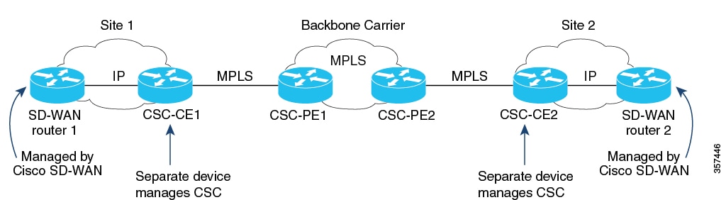
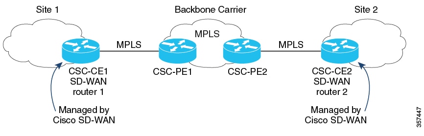
The feature adds support for carrier supporting carrier (CSC) connectivity on Cisco IOS XE Catalyst SD-WAN devices.

CSC enables you to interconnect IP or multiprotocol label switching (MPLS) networks operating at different sites over an MPLS backbone network. Using CSC requires an edge router that supports CSC functionality, called a carrier edge (CE) device, at each site. This feature enables a Cisco IOS XE Catalyst SD-WAN device to serve as a CE device, making it unnecessary to have a separate dedicated CE device at each site managed by Cisco Catalyst SD-WAN.

Carrier supporting carrier

A carrier supporting carrier (CSC) is a hierarchical VPN model that

  • allows organizations to interconnect their IP or MPLS networks located at different sites,

  • operates over an MPLS backbone network, and

  • eliminates the need for organizations to build and maintain their own MPLS backbone.

Components of carrier supporting carrier

  • Backbone carrier: The service provider operates the backbone network. Typically, the backbone carrier network employs multiple segments to segregate the traffic of different customer carriers that share it. The same organization as the customer carriers or a different organization manages the backbone carrier.

  • Customer carrier: An organization that uses the backbone network to route traffic from one site to another. The customer carrier may be part of the organization that operates the backbone network, or may be independent.

  • CSC-CE: The customer edge (CE) device operates within a local site network and connects the site to the backbone carrier using an MPLS connection. It uses the backbone carrier to connect to other sites.

  • CSC-PE: The provider edge (PE) device operates within the backbone carrier network and connects to CSC-CE devices at customer sites using an MPLS connection.

Benefits of carrier supporting carrier

A Cisco IOS XE Catalyst SD-WAN device functions as an customer edge device at a site requiring CSC, eliminating the need for a separate CE router.

Traffic flow configuration between CSC-CE and CSC-PE devices

The traffic flow configuration between CSC-CE and CSC-PE devices determines how service VPN, control, and BFD probe traffic is routed based on available MPLS and internet connections. This configuration optimizes network resources, ensures efficient traffic handling, and supports high availability in service provider networks.

Traffic flow

When a CSC-CE device has only an MPLS connection to its neighboring CSC-PE device, it sends all traffic, including service VPN traffic, control traffic, and Cisco Catalyst SD-WAN bidirectional forwarding detection (BFD) probe traffic, over the MPLS connection.

When a CSC-CE device has both an MPLS connection to the neighboring CSC-PE device and a separate internet connection, it routes traffic as follows:

  • Based on the configured traffic policy, it can send control traffic and BFD probe traffic over either the internet or the MPLS connection.

  • It sends service VPN traffic exclusively over the MPLS connection.

Label switching

When traffic uses an MPLS connection between a CSC device and the backbone carrier, the backbone carrier manages the traffic through label-switched paths and does not store any information about the customer carrier routes.

Edge device functioning as a CSC-CE device

The Cisco IOS XE Catalyst SD-WAN software simplifies carrier supporting carrier network topologies by enabling a single device to perform both SD-WAN edge and CSC-CE functions.

Before Cisco IOS XE Catalyst SD-WAN Release 17.6.1a

In releases earlier than 17.6.1a, each site in a CSC network topology used two separate devices: an edge device managed by Cisco Catalyst SD-WAN and a dedicated CSC-CE device. This is because the Cisco IOS XE Catalyst SD-WAN device could not function as a CSC-CE. See the illustration for the CSC topology before Cisco IOS XE Catalyst SD-WAN Release 17.6.1a.

Figure 1. Carrier supporting carrier with Cisco Catalyst SD-WAN, before Cisco IOS XE Catalyst SD-WAN Release 17.6.1a

From Cisco IOS XE Catalyst SD-WAN Release 17.6.1a

From Cisco IOS XE Catalyst SD-WAN Release 17.6.1a, a Cisco IOS XE Catalyst SD-WAN device can function as a CSC-CE, removing the need for a separate dedicated CSC-CE device. See the illustration for the simplified CSC topology with Cisco IOS XE Catalyst SD-WAN devices providing CSC-CE functionality.

Figure 2. Carrier supporting carrier with Cisco Catalyst SD-WAN, Cisco IOS XE Catalyst SD-WAN Release 17.6.1a and later

Use cases for carrier supporting carrier

Carrier Supporting Carrier (CSC) enables secure, private transport of multiple customer networks over a shared backbone.

Global organizations

Global organizations can use Cisco Catalyst SD-WAN to support CSC with a backbone carrier, enabling multiple, separate divisions of an organization to maintain private traffic while sharing a common backbone carrier.

Service providers

Service providers that implement a CSC topology can benefit from Cisco Catalyst SD-WAN, as it allows carrier edge devices to handle CSC functionality without requiring a separate device.

Configure carrier supporting carrier

Use one of these methods to configure carrier supporting carrier.

Configure carrier supporting carrier using a feature template

Follow these steps to configure a CE device for CSC using a new feature template in Cisco SD-WAN Manager.

Procedure


Step 1

Create a new device template.

  1. From the Cisco SD-WAN Manager menu, choose Configuration > Templates.

  2. Choose Device Templates, and click Create Template.

  3. From the drop-down list, select From Feature Template.

Note


In Cisco vManage Release 20.7.x and earlier releases, Device Templates is titled as Device.

Step 2

Enter device details.

  • In the Device Model field, choose the correct device model.

  • In the Device Role field, select SDWAN Edge.

  • In the Template Name field, enter a name for the template.

Step 3

Configure VPN settings.

  1. In the Transport & Management VPN section, under Cisco VPN 0, choose a template to configure VPN 0.

    For more, see Configure Interfaces in the WAN Transport VPN (VPN 0).

  2. In the Cisco VPN Interface Ethernet field, choose a template to configure the interface.

    For more information, see Configure VPN Ethernet Interface.

Step 4

In the Transport & Management VPN section, click Cisco BGP to add the Cisco BGP field.

For more information, see see Configure BGP Using SD-WAN Manager Templates.

Step 5

In the MPLS Interface section, under Interface Name 1, enter the interface used to connect the device to the backbone carrier.

Step 6

In the Neighbor section, click Advanced Options to configure CSC options.

Table 2. Configure CSC options

Field

Description

Send label

Choose On to enable CSC support.

Explicit null

Choose On if the device uses a loopback WAN interface.

As override

Choose On if CE1 and CE2 use the same autonomous system (AS) number.

Allowas in

Choose On if the two CE sites use the same AS number.

Step 7

Click Save to save the BGP configuration.

Step 8

Click Create to create the feature template.

The Configuration > Templates page displays the available templates.

Step 9

Attach the template to a device.

  1. On the Configuration > Templates page, click Device Templates.

  2. For the new template, click and choose Attach Devices.

  3. Move a device to the Selected Devices column and click Attach.


Configure carrier supporting carrier using CLI

You can use the BGP feature template to configure CSC instead of CLI commands.

Before you begin

Apply a BGP configuration to a Cisco IOS XE Catalyst SD-WAN device before you configure it for CSC-CE functionality.

Follow these steps to configure a CE device for CSC using the CLI.

Procedure


Step 1

Configure CSC-CE1

  1. Map MPLS labels to VRFs.

    The device checks the MPLS label of incoming traffic and uses the IP lookup table of the VRF mapped to that label.For example, if the MPLS label 10 maps to VRF 1, the router uses the IP lookup table of VRF 1 for traffic with label 10.

    device# config-transaction
    device(config)# mpls label mode all-vrfs protocol bgp-vpnv4 per-vrf
    device(config)# mpls label mode all-vrfs protocol bgp-vpnv6 per-vrf
    device(config)# mpls label range min-label max-label static min-static-label max-static-label
  2. Enable MPLS on the interface.

    device(config)# interfaceinterface
    device(config-if)# mpls bgp forwarding
  3. Configure BGP.

    device(config)# router bgp bgp-number
    device(config-router)# neighbor neighbor-ip> allowas-in
  4. Advertise MPLS labels when using a loopback WAN interface.

    device(config-router)# neighbor <neighbor-ip> send-label explicit-null

    Note


    Using send-label explicit-null on non-loopback interfaces does not affect performance.

Step 2

Configure CSC-CE2

  1. Map MPLS labels to VRFs.

    device# config-transaction
    device(config)# mpls label mode all-vrfs protocol bgp-vpnv4 per-vrf
    device(config)# mpls label mode all-vrfs protocol bgp-vpnv6 per-vrf
    device(config)# mpls label range min-label max-label static min-static-label max-static-label
  2. Enable MPLS on the interface.

    device(config)# interface interface
    device(config-if)# mpls bgp forwarding
  3. Configure BGP.

    evice(config)# router bgp bgp-number
    Device(config-router)# neighbor neighbor-ip as-override
    Device(config-router)# neighbor neighbor-ip send-label explicit-null

The following example shows CSC-CE1 and CSC-CE2 configurations with BGP and MPLS:

  • CSC-CE1: 10.1.1.10

  • CSC-CE2: 10.1.1.20

  • CSC-PE1 (neighbor of CSC-CE1): 10.2.2.10

  • CSC-PE2 (neighbor of CSC-CE2): 10.2.2.20

CSC-CE1 Configuration

mpls label mode all-vrfs protocol bgp-vpnv4 per-vrf
mpls label mode all-vrfs protocol bgp-vpnv6 per-vrf
mpls label range 100000 1048575 static 16 99

interface GigabitEthernet2
 no shutdown
 mpls bgp forwarding
 ip address 10.1.1.15 255.255.255.0

router bgp 10
 bgp log-neighbor-changes
 bgp router-id 172.16.255.15
 neighbor 10.1.1.20 remote-as 100
 neighbor 10.1.1.20 fall-over bfd
 address-family ipv4 unicast
  maximum-paths 4
  neighbor 10.1.1.20 activate
  neighbor 10.1.1.20 advertisement-interval 30
  neighbor 10.2.2.10 allowas-in
  neighbor 10.2.2.10 send-label explicit-null
  neighbor 10.1.1.20 send-community both
 exit-address-family
 timers bgp 60 180

CSC-CE2 Configuration

mpls label mode all-vrfs protocol bgp-vpnv4 per-vrf
mpls label mode all-vrfs protocol bgp-vpnv6 per-vrf
mpls label range 100000 1048575 static 16 99

interface GigabitEthernet5
 ip address 10.0.6.11 255.255.255.0
 negotiation auto
 mpls bgp forwarding

router bgp 10
 bgp log-neighbor-changes
 bgp router-id 172.16.255.11
 neighbor 10.1.1.10 remote-as 200
 address-family ipv4 unicast
  neighbor 10.1.1.10 activate
  neighbor 10.1.1.10 advertisement-interval 30
  neighbor 10.2.2.20 as-override
  neighbor 10.2.2.20 send-label explicit-null
  network 10.0.7.0 mask 255.255.255.0
  redistribute connected
  redistribute static
 exit-address-family

Verify device configuration for carrier supporting carrier

To verify if a device is correctly configured to reach the remote CSC-CE device using MPLS-labeled routing.

Procedure


Step 1

Run the following command on the device:

Example:

show ip route remote-csc-ce-device-address

Step 2

Confirm if the output displays a routing entry for the remote site IP address.

Step 3

Check if the output includes one or more routing descriptor blocks that describe the next-hop addresses for the path to the remote CSC-CE device.

Step 4

Ensure that each descriptor block contains an MPLS label.

  • If the device is configured correctly, the output shows:
    Device# show ip route 10.0.1.100
    Routing entry for 10.0.1.0/24
    ...
    Routing Descriptor Blocks:
    * 10.1.1.100, from 10.1.1.100, 00:00:50 ago
    ...
    MPLS label: 26
  • If the device is not configured correctly, the output shows:

    % Subnet not in table