Cisco Catalyst SD-WAN Systems and Interfaces Configuration Guide, Cisco IOS XE Catalyst SD-WAN Release 17.x
Bias-Free Language
The documentation set for this product strives to use bias-free language. For the purposes of this documentation set, bias-free is defined as language that does not imply discrimination based on age, disability, gender, racial identity, ethnic identity, sexual orientation, socioeconomic status, and intersectionality. Exceptions may be present in the documentation due to language that is hardcoded in the user interfaces of the product software, language used based on RFP documentation, or language that is used by a referenced third-party product. Learn more about how Cisco is using Inclusive Language.
This table describes the developments of this feature, by release.
Table 1. Feature History
Feature Name
Release Information
Description
Layer 2 (L2) VPN
Cisco Catalyst SD-WAN Manager Release 20.14.1
Cisco IOS XE Catalyst SD-WAN Release 17.14.1a
The feature adds Layer 2 VPN support on the Cisco Catalyst SD-WAN overlay network.
It allows you to configure Layer 2 point-to-point and point-to-multipoint connections within the Cisco Catalyst SD-WAN fabric.
Layer 2 (L2) VPN Multihoming and Hub-and-Spoke Support
Cisco Catalyst SD-WAN Manager Release 20.15.1
Cisco IOS XE Catalyst SD-WAN Release 17.15.1a
With this feature, you can configure Layer 2 VPN on multiple devices on the same site in an active-standby configuration.
This feature also enables Layer 2 connections using an indirect path, such as a hub, for point-to-multipoint connections within
the Cisco Catalyst SD-WAN fabric.
Layer 2 VPNs within the SD-WAN overlay network
Layer 2 VPN within the Cisco Catalyst SD-WAN overlay network is a network feature that
enables Layer 2 connectivity across the SD-WAN fabric for legacy systems and non-IP applications,
supports point-to-point (P2P) and point-to-multipoint (P2MP) L2VPN services with options for single homing, multihoming, and
topologies including full mesh and hub-and-spoke, and
provides MAC learning through OMP protocol (Control Plane), along with features such as ingress replication for broadcast,
unknown-unicast, and multicast (BUM) traffic.
Starting from Cisco IOS XE Catalyst SD-WAN Release 17.14.1a, the following L2VPN features are supported:
Point-to-point L2VPN Service (P2P)
Point-to-Multipoint L2VPN Service (P2MP)
Single homing
Flood and Learn in WAN and LAN
Ingress replication for Broadcast, Unknown-unicast and Multicast (BUM)
Full mesh topology only
Starting from Cisco IOS XE Catalyst SD-WAN Release 17.15.1a, the following L2VPN features are supported:
Multihoming for P2P and P2MP
Hub-and-spoke topology support for L2VPN services
The MAC learning mode (previously the Flood and Learn in WAN and LAN) is changed to learning through OMP protocol (that is,
Control Plane).
Note
From Cisco IOS XE Catalyst SD-WAN Release 17.18.1a, you can adjust the TCP Maximum Segment Size (MSS) even for a TCP packet encapsulated in an MPLS label. You can set the TCP
MSS per the Path Maximum Transmission Unit (PMTU) with 30 bytes to account for Layer 2 headers, such as Ethernet, VLAN tags
and MPLS headers.
For IPv4, the TCP MSS is set per PMTU with 80 bytes for IPv4 and TCP headers and an additional 30 bytes for Layer 2 headers.
For example, if the PMTU is 1438, the TCP MSS is set as 1328 (1438 - 80 - 30).
For IPv6, the TCP MSS is set per PMTU with 100 bytes for IPv6 and TCP headers and an additional 30 bytes for Layer 2 headers.
For example, if the PMTU is 1438, the TCP MSS is set as 1308 (1438-100-30).
This change helps prevent drop in TCP sessions, improving overall network performance and reliability.
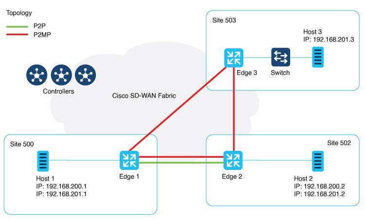
Network Topology for Layer 2 Connections
Figure 1. Topology
This illustration shows three sites and shows P2P (green line) and P2MP (red lines) connections between edge routers at the
sites.
Point-to-Point (P2P): Connects sites 500 and 502 with a dedicated Layer 2 VPN. The L2VPN connection between the two sites
allows Host 1 and Host 2 to interact.
Point-to-Multipoint (P2MP): Connects sites 500, 502, and 503 with Layer 2 VPN. Host 1 communicates with both Host 2 and Host
3 across a Layer 2 multipoint network.
The L2VPN connections use existing Cisco Catalyst SD-WAN tunnels.
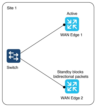
Figure 2. Multihoming
The illustration shows two edge routers on the same site connected to a switch. For an (instance-id + vc), one router is active
and the other is on standby. (instance-id +vc) maps to a bridge domain and a bridge-domain maps to a VLAN (or a VLAN range).
The router on standby blocks bidirectional traffic for that VLAN.
Multihoming supports L2VPN configuration on up to two edge devices on the same site, thereby providing redundancy for L2VPN
service over SD-WAN.
Multihoming allows an active-standby scenario where one device is chosen as active and the other as standby. This provides
automated failover. It determines which of the two edge devices should be active and which one should be on standby. When
the OMP timer expires on the controller, it marks the L2VPN status route as stale, and notifies other edges.
Role determination for an Active and Standby device
The active and standby role between edge devices is automatically determined by with this algorithm: (SDWAN-Instance-ID +
VC-ID) modular 2.
If the modular result is 0, the edge with lower system-ip is selected as the active device. The edge with the higher system-ip
is selected as the standby device.
If the modular result is 1, the edge with higher system-ip is selected as the active device. The edge with the lower system-ip
is selected as the standby device.
Example:
There are two WAN edge devices. WAN edge 1 has a system-ip of 172.16.255.10. WAN edge 2 has a system-ip of 172.16.255.11.
For sdwan-instance-id 100, vc-id 2, WAN edge 1 with the lower system-ip is selected as the active device. WAN edge 2 is the
standby device.
For sdwan-instance-id 100, vc-id 1, WAN edge 2 with the higher system-ip is selected as the active device. WAN edge 1 is the
standby device.
If a failure occurs on the service side of one of the edge devices, the controller is notified about a change to the L2VPN
status route, and other edge routers can switchover traffic to the new active device.
Supported platforms for Layer 2 VPN
All Cisco IOS XE Catalyst SD-WAN devices.
Restrictions for Layer 2 VPN
Supported configuration CLI templates for Layer 2 VPN
Only CLI template or CLI add-on template configuration is supported for Layer 2 VPN.
LAN side interface limitation in single homing and multihoming
For both single homing and multihoming, only one LAN side interface is supported in a bridge-domain.
Point-to-Multipoint (P2MP) requirements for hub and spoke connectivity
P2P configuration between two spokes is not supported. In such cases, use P2MP instead of P2P.
Note
P2P configuration between hub and spoke is supported.
Multihoming support only for dual homing
Starting from Cisco IOS XE Catalyst SD-WAN Release 17.15.1a, multihoming only supports dual homing.
Layer 2 VPN limitations for hub-and-spoke topology
Starting from Cisco IOS XE Catalyst SD-WAN Release 17.15.1a, hub-and-spoke topology is supported for Layer 2 VPN. It is limited by:
No support for point-to-point Layer 2 VPN service between spokes.
Support for up to 6000 spokes and 6000 sites within the same Layer 2 VPN in hub-and-spoke topology, and
Support for only 256 sites within the same Layer 2 VPN in a non-hub-and-spoke design.
Methods to configure Layer 2 VPN using CLI template
Using these procedures, configure a Layer 2 VPN on a Cisco Catalyst SD-WAN overlay network.
The instance ID is a unique identifier for each L2VPN connection, and must not overlap or be shared with any Layer 3 VRFs
in the SD-WAN fabric. For example, you cannot use L2VPN instance 10 and vrf definition 10.
Step 2
Configure a bridge-domain.
bridge-domainbridge-id
Step 3
Configure a Layer 2 interface on a Cisco IOS XE Catalyst SD-WAN device.
A rewrite is used to modify the default VLAN tag. If you have not configured rewrite under service instance, dot1q must be
the same at all sites participating in the Layer 2 network. The rewrite option in a Layer 2 configuration modifies the VLAN
tags of packets as they ingress or egress an interface. To use the rewrite option, you need to configure Ethernet Virtual
Connections (EVCs) on edge routers (Cisco ASR 1000 Series). For more information about configuring an EVC, see Configuring Ethernet Virtual Connections on a Cisco Router.
Configure a point-to-point Layer 2 VPN using CLI template
Before you begin
You can use one L2VPN instance ID for one or more bridge domains. It must be the same at both ends of the circuit.
To identify a particular bridge-domain, use Virtual Circuit (VC) ID. This ID is the identifier of the virtual circuit between
the Cisco IOS XE Catalyst SD-WAN devices.
To create a P2P pseudowire, L2VPN instance ID, and VC ID must be the same on different Cisco IOS XE Catalyst SD-WAN devices.
Remote-site-id is only supported for P2P configuration.
The following configures Site A using Cisco Catalyst 8000V Edge Software to manage traffic through GigabitEthernet5, which
is linked to the Layer 2 network that provides connectivity to Site B.
l2vpn sdwan instance 100 point-to-point

interface GigabitEthernet5
 service instance 100 ethernet
  encapsulation dot1q 2002
  !
bridge-domain 100
 member GigabitEthernet5 service-instance 100
 member sdwan-instance 100 remote-site 502 vc-id 100 single-homing
Configure an edge router at Site B for point-to-point Layer 2 VPN using CLI temple
Site B uses an edge router and Switchport Ethernet interface.
Follow these steps to configure an edge router at Site B for point-to-point Layer 2 VPN.
Procedure
Step 1
Define the L2VPN instance for point-to-point service.
The following configures Switchport GigabitEthernet 0/1/7 at Site B to connect to the interface with a Cisco ISR1100-8P device.
l2vpn sdwan instance 100 point-to-point
vlan 2002
 name L2vpn
interface Vlan2002
 service instance 100 ethernet
  encapsulation dot1q 2002
  no shutdown
  !
interface GigabitEthernet 0/1/7
 switchport access vlan 2002
bridge-domain 100
 member Vlan2002 service-instance 100
 member sdwan-instance 100 remote-site 500 vc-id 100 single-homing
After configuring the point-to-point L2VPN service on both sites, you can integrate these configuration blocks into your CLI
Template or CLI Add-On Feature Template. This template can then be used to deploy the configuration across the relevant devices
in the Cisco Catalyst SD-WAN fabric. Verify the connectivity and functionality of the L2VPN service following the deployment
to confirm that the bridge between site A and site B is operational.
Configure a point-to-multipoint Layer 2 VPN using CLI template
By default, CLI templates execute commands in global config mode.
One L2VPN instance ID can be used by one or more bridge domains. VC ID is used to identify a particular bridge-domain.
L2VPN instance ID and VC ID must be the same on different edge devices.
Follow these steps to configure P2MP Layer 2 VPN over Cisco Catalyst SD-WAN overlay, connecting a local Layer 2 network at
site A to multiple remote sites (B and C). Site A uses Gigabit Ethernet interface to connect to the Layer 2 network for bridging.
The following configures Switchport GigabitEthernet 0/1/7 at Site B to connect to the interface with a Cisco ISR1100-8P device.
l2vpn sdwan instance 100 point-to-point
vlan 2002
 name L2vpn
interface Vlan2002
 service instance 100 ethernet
  encapsulation dot1q 2002
  no shutdown
  !
interface GigabitEthernet 0/1/7
 switchport access vlan 2002
bridge-domain 100
 member Vlan2002 service-instance 100
 member sdwan-instance 100 remote-site 500 vc-id 100 single-homing
After configuring the point-to-point L2VPN service on both sites, you can integrate these configuration blocks into your CLI
Template or CLI Add-On Feature Template. This template can then be used to deploy the configuration across the relevant devices
in the Cisco Catalyst SD-WAN fabric. Verify the connectivity and functionality of the L2VPN service following the deployment
to confirm that the bridge between site A and site B is operational.
Configure an edge router at Site C for point-to-point Layer 2 VPN using CLI template
Before you begin
Repeat the same steps as for branch router C, substituting the specific interface used on site B.
Follow these steps to configure an edge router at Site C for point-to-point Layer 2 VPN.
Procedure
Step 1
Define the L2VPN instance for multipoint service on the branch router:
l2vpn sdwan instanceinstance-idmultipoint
Step 2
Define the VLAN for the L2VPN on the branch router:
vlanvlan-idname L2vpn
Step 3
Configure the VLAN interface on the branch router:
This section provides an example configuration for P2MP L2VPN service within the Cisco Catalyst SD-WAN overlay network, connecting
a local Layer 2 network at site A to multiple remote sites (B and C). Site A uses GigabitEthernet6 interface to connect to
the L2 network for bridging.
Verify the connectivity and functionality of the P2MP L2VPN service and ensure that all sites are correctly bridged.
Site A is using a Cisco Catalyst 8000V edge router, where GigabitEthernet6 is connected to the Layer 2 network that bridges
to site B and site C.
l2vpn sdwan instance 200 multipoint

vlan 2001
 name L2MPvpn

interface Vlan2001
 service instance 200 ethernet
  encapsulation dot1q 2001
  no shutdown
  !
interface GigabitEthernet 0/1/6
 switchport access vlan 2001

bridge-domain 200
 member Vlan2001 service-instance 200
 member sdwan-instance 200 vc-id 200 single-homing
Configure branch router C:
Repeat the same steps as for branch router B, substituting the specific interface used on router 503. In this example, we
have used the GigabitEthernet 0/1/6 interface.
l2vpn sdwan instance 200 multipoint

vlan 2001
 name L2MPvpn

interface Vlan2001
 service instance 200 ethernet
  encapsulation dot1q 2001
  no shutdown
  !
bridge-domain 200
 member Vlan2001 service-instance 200
 member sdwan-instance 200 vc-id 200 single-homing
Configure a Layer 2 VPN Switchport using CLI template
If your device such as Cisco ISR1121-8P or similar has embedded switchports and you want to use one of them for the L2VPN
services, configure a VLAN interface first and then assign that VLAN to your switchport as described in this section.
To support a Layer 2 switchport, configure a service instance in the VLAN interface. In the VLAN interface, a packet always
has the dot1q tag even when the Layer 2 switchport is configured with switchport mode access. Therefore, the dot1q tag is
mandatory in the service instance of the VLAN interface.
This following section provides steps to configure a Layer 2 switchport for P2MP (applicable for devices with embedded switchports).
You can also configure a Layer 2 switchport for P2P by updating the Layer 2 VPN instance command.
Site A is using an edge router, where the Ethernet interface is connected to the Layer 2 network that bridges to Site B and
Site C.
Follow these steps to configure a Layer 2 VPN Switchport using CLI template.
Procedure
Step 1
Define the Layer 2 VPN instance for multipoint service on the branch routers:
l2vpn sdwan instanceinstance-idmultipoint
Step 2
Define the VLAN for the Layer 2 VPN on the branch routers:
vlanvlan-idname l2vpn
Step 3
Configure the Ethernet interface on the routers:
interfaceinterface-name
Step 4
Set the switch port access VLAN and switchport mode to access to accept traffic only from the specified VLAN:
switchport access Vlanvlan-id
Step 5
Configure the VLAN interface on a router and disable the IP address assignment
interfaceinterface-nameno ip addressservice instanceinstance-idethernetencapsulation dot1qvlan-id
Step 6
Define the bridge-domain on the data center router and associate it with the interface and L2VPN instance:
The following configures a Layer 2 VPN Switchport to integrate a multipoint SD-WAN instance and bridge-domain. This configuration
sets up GigabitEthernet0/1/2 as an access port for VLAN 201.
l2vpn sdwan instance 200 multipoint

interface GigabitEthernet0/1/2
 switchport access Vlan 201
 switchport mode access

interface Vlan201
 no ip address
 service instance 200 ethernet
  encapsulation dot1q 201
  !

bridge-domain 201
 member Vlan201 service-instance 200
 member sdwan-instance 200 vc-id 201 single-homing
Methods to verify Layer 2 VPN using CLI
To verify Layer 2 VPN using CLI, use these methods.
To view the remote peer information, system IP, status, and related information, use the show l2vpn sdwan [instanceinstance-id][vc-idvc-id] command.
This is an example for a Cisco IOS XE Catalyst SD-WAN device.
Device# show l2vpn sdwan instance 13 vc-id 13
VC_ID: 13 Bridge-domain: 13
Local l2vpn status: UP
Local Pseudoports: GigabitEthernet7 service instance 13
View L2VPN information learned through OMP route on a Cisco SD-WAN Controller
To view the specific L2-route or path learned in the specific VPN and virtual circuit, use the show sdwan omp l2-routes[vpnvpn-id] [vc-idvc-id] command. If the vpn and vc-id are not included, the command shows Layer 2 routes learned through OMP from all VPNs across the Cisco Catalyst SD-WAN fabric.
This is a sample output from the show omp l2-routes command displaying Layer 2 routes learned through OMP for Cisco SD-WAN Controllers.
To verify information related to bridge domains within the context of Forwarding Table Management Daemon (FTMD), use the show platform software sdwan ftmd bridge-domain command on a device.
This is a sample output from the show platform software sdwan ftmd bridge-domain command that displays information related to bridge domains within the context of Forwarding Table Management Daemon (FTMD).
View Cisco Catalyst SD-WAN Flood List Information and Packet Counters in Data Plane
To verify information related to Cisco Catalyst SD-WAN flood list information, use the show platform hardware qfp active feature bridge-domain datapathbridge-domain-idsdwan-flood-list command.
This is a sample output from the show platform hardware qfp active feature bridge-domain datapathbridge-domain-idsdwan-flood-list command that displays the Cisco Catalyst SD-WAN flood list information.
To verify information related to a QuantumFlow Processor (QFP) hardware module packet counters for a specific bridge domain
within the data path, use the show platform hardware qfp active feature bridge-domain datapathbridge-id command.
This is a sample output from the show platform hardware qfp active feature bridge-domain datapathbridge-id command to display a QFP hardware module packet counters for a specific bridge domain within the data path.
Device# show platform hardware qfp active feature bridge-domain datapath 200
QFP L2BD Bridge Domain information

BD id                  : 200
State enabled          : Yes
Aging timeout (sec)    : 300
Aging active entry     : Yes
Max mac limit          : 65536
Unkwn mac limit flood  : Yes
mac_learn_enabled      : Yes
mac_learn_controled    : No
Unknown unicast olist  : Yes
otv_aed_enabled : No
otv_enabled : No
mcast_snooping_enabled : No
Feature : sdwan
SISF snoop protocols   : None
Sdwan instance id      : 200
Mac learned            : 0
BDI outer vtag         : 00000000
BDI inner vtag         : 00000000

Replication tree info:
  Global replication    : depth encode 0X1000001, (head 0XE4E90000)
  Split-horizon-group 0 : depth encode 00000000, (head 00000000)
  Split-horizon-group 1 : depth encode 00000000, (head 00000000)
Bridge Domain statistics

Total bridged                pkts : 0          bytes: 0
Total unknown unicast        pkts : 0          bytes: 0
Total broadcasted            pkts : 0          bytes: 0
Total to BDI                 pkts : 0          bytes: 0
Total injected               pkts : 0          bytes: 0
Total mac-sec violation drop pkts : 0          bytes: 0
Total mac-sec move drop      pkts : 0          bytes: 0
Total mac-sec unknown drop   pkts : 0          bytes: 0
Total source filter drop     pkts : 0          bytes: 0
Total bfib policy drop       pkts : 0          bytes: 0
Total replication start drop pkts : 0          bytes: 0
Total recycle tail drop      pkts : 0          bytes: 0
Total static MAC move drop   pkts : 0          bytes: 0
Total BD disabled drop       pkts : 0          bytes: 0
Total STP state drop         pkts : 0          bytes: 0
Total UUF suppression drop   pkts : 0          bytes: 0
Total sisf ctrl punt         pkts : 0          bytes: 0
Total sisf ctrl drop         pkts : 0          bytes: 0
Total p2p lan to wan         pkts : 0          bytes: 0
Total p2p wan to lan         pkts : 0          bytes: 0
Monitor configured layer 2 VPN using CLI
This is a sample output from the show l2vpn sdwan all command. The following examples show the configuration and status information for Layer 2 VPN instances within a Cisco Catalyst
SD-WAN overlay network. The output includes details for both point-to-point (P2P) and point-to-multipoint (P2MP) topologies.
Example 1: The example shows the L2VPN SD-WAN instance for instance 100 for point-to-point connectivity.
Device# show l2vpn sdwan all
L2VPN sdwan Instance : 100
VPN Type : point-to-point
  VC_ID: 100 Bridge-domain: 100 UP
    Local l2vpn status: UP
    Local Pseudoports: GigabitEthernet5 service instance 100
    Remote Site: 53
      System IP          status       up/down    color           encap    label  DF
      10.100.31.53       DOWN         00:15:04   public-internet ipsec    1023   N/A
Example 2: The example shows all the Layer 2 VPN SD-WAN instance for instance 200 for point-to-point connectivity.
Device# show l2vpn sdwan all
L2VPN sdwan Instance : 200
VPN Type : multipoint
IP Local-learning    : Disabled
Flooding Suppression : Disabled
  VC_ID: 200 Bridge-domain: 200 UP
    Local l2vpn status: UP
    Local Pseudoports: GigabitEthernet5 service instance 200
    Remote Site: 50
      System IP          status       up/down    color           encap    label  DF
      10.100.31.50       UP           00:04:14   public-internet ipsec    1008   N/A

    Remote Site: 53
      System IP          status       up/down    color           encap    label  DF
      10.100.31.53       UP           00:15:00   public-internet ipsec    1025   N/A
This is a sample output from the show l2vpn sdwan instance instance-id vc-id vc-idpeers command. The following examples show information about a specific Cisco Catalyst SD-WAN Layer 2 VPN instance (instance 200)
and its associated virtual circuit (vc-id 200), including details about its peer connections.
show l2vpn sdwan instanceinstance-idvc-idvc-idpeers
Example 1
Device1# show l2vpn sdwan instance 200 vc-id 200 peers
    Remote Site: 50   MACs Learn: 0
      System IP          status       up/down    color           encap    label  DF
      10.100.31.50       UP           00:19:54   public-internet ipsec    1008   N/A
    Remote Site: 53   MACs Learn: 0
      System IP          status       up/down    color           encap    label  DF
      10.100.31.53       UP           00:30:40   public-internet ipsec    1025   N/A
Example 2
Device# show l2vpn sdwan instance 200 vc-id 200 peers
     Remote Site: 1   MACs Learn: 0
      System IP          status       up/down    color           encap    label  DF
      10.100.31.1        UP           00:30:13   public-internet ipsec    1014   N/A

 Feedback