Cisco Spaces: Captive Portal App

This chapter describes how to create a captive portal using Cisco Spaces.

Create and manage portal

A portal is a user interface that appears when a Wi-Fi user connects to an SSID. You can create the captive portals using Cisco Spaces and enhance them with portal modules provided by Cisco Spaces.

Cisco Spaces also allows you to create your own portals (Enterprise Captive Portals) for onboarding end users who connect to Wi-Fi. For more information on Enterprise Captive Portals, refer to Enterprise Captive Portals.

Prerequisites for creating a portal

  • To specify the locations for which the portal is applicable, you must define the location hierarchy. For more information on defining the location hierarchy, refer to the Defining the Location Hierarchy section.

  • To configure social authentication for the portal, configure your social app and then add it to Cisco Spaces. For more information on configuring for social authentication, refer to the Social Authentication for Portals section.

  • To configure SMS-based authentication for the portal, configure the SMS gateway. For more information on configuring the SMS gateway, refer to the Configure an SMS gateway in Cisco Spaces section.

Bandwidth requirements

For captive portals, we recommend a minimum bandwidth of 30Mbps for good end user experience.

This table shows the response time for loading the captive portal based on the bandwidth.

Table 1.

Bandwidth

Number of users

Response (in seconds)

1 Mbps

1

5.86

2

5.49

3

5.40

4

5.63

5

5.92

2 Mbps

1

5.09

2

5.10

3

5.04

4

5.25

5

5.16

6

5.23

7

5.26

8

5.30

9

5.34

10

5.40

11

5.49

5Mbps

5

4.92

10

4.98

11

5.05

12

5.08

13

5.11

14

5.13

15

5.17

16

5.18

20

5.25

7Mbps

25

5.13

30

5.20

31

5.23

32

5.26

33

5.29

34

5.33

9Mbps

30

4.93

35

4.98

40

5.05

41

5.07

42

5.10

43

5.13

44

5.15

45

5.17

46

5.19

47

5.15

11 Mbps

35

4.68

40

4.91

50

5.05

55

5.16

56

5.18

57

5.20

58

5.24

59

5.28

60

5.25

61

5.30

Sample portals

Cisco Spaces provides sample portals for various authentication types.

  • Email authentication with data capture

  • Inline SMS with password verification & data capture

  • Inline social authentication

  • SMS with password verification & data capture

  • SMS with link verification

  • Email authentication

  • User agreements

These templates are intended as a reference for creating captive portals.

To view and make a copy of the sample portal, perform these steps:

Procedure


Step 1

In the Cisco Spaces dashboard, choose Home.

Step 2

In the window that appears, choose Captive Portal.

Step 3

In the Captive Portal window, choose Portal in the left pane.

The sample portal for various authentication types are displayed at the bottom of the portal list.

Step 4

Click the Make a Copy icon at the far right of the sample portal that you want.

Step 5

In the portal wizard screen that appears, specify a name for the captive portal.

Step 6

If necessary, customize the portal configuration. Save the portal.

Step 7

Save the portal.


Create a portal

Enable secure guest access by creating a customizable portal to control user onboarding and data capture.

When defining a portal, you can also configure the locations for which the portal must be available.

To create a portal, perform these steps:

Procedure


Step 1

In the Cisco Spaces dashboard, choose Home. In the window that appears, choose Captive Portal. In the Captive Portal window that appears, choose Portal in the left pane. Click Create New.

The Portal window appears.
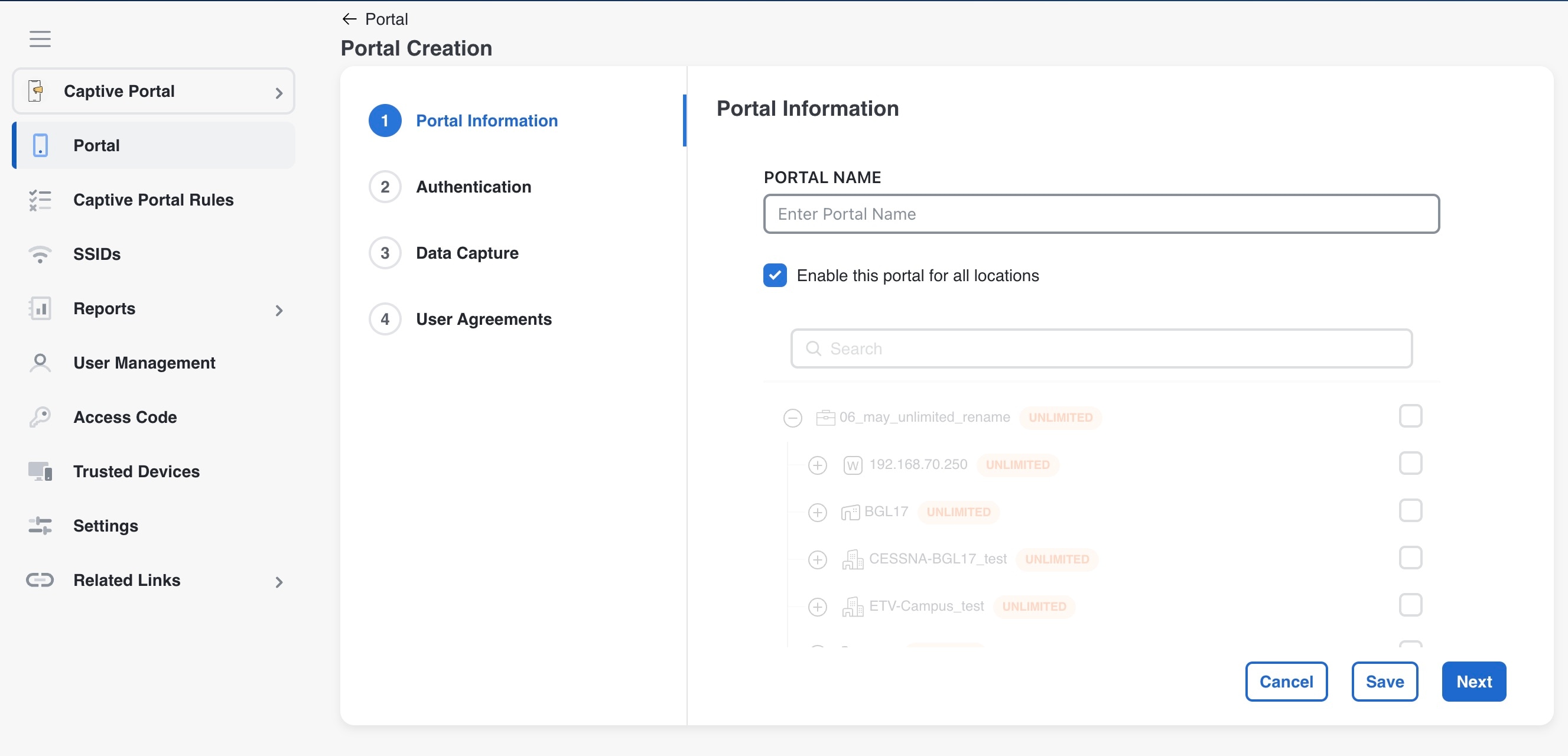
Step 2

In the Portal Name field, enter a name for portal. If you want this portal to be available only for certain locations, uncheck the Enable this portal forall locations check box. Click Next. The Authentication window appears.

Note

 
By default, the Enable this portal for all locations check box is checked so that the portal is available for all the location in the location hierarchy.

Step 3

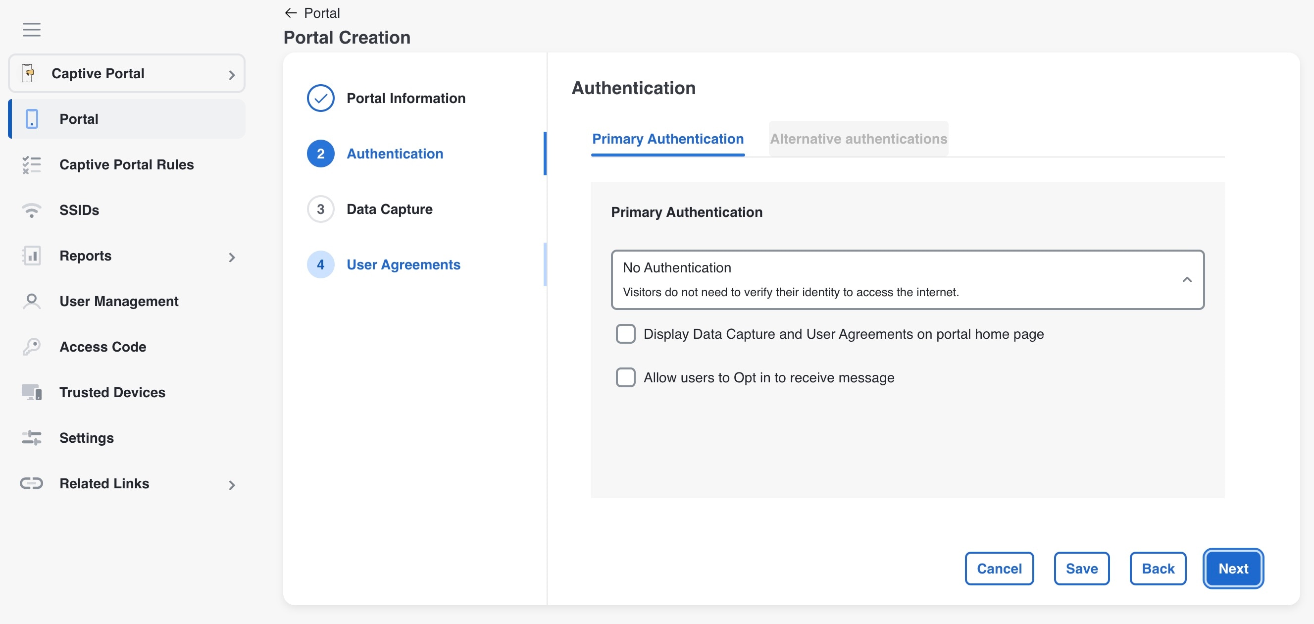
In the Authentication window, select the authentication type that you want apply for the portal. There is a Primary Authentication tab which allows users to select only one authentication method during a session. The Alternate Authentication option allows the user to add multiple authentication methods. After specifying the details for the authentication type, click Next. The Data Capture window appears.

Based on the authentication type selected additional fields appear. For more information on various authentication types, see the Configure authentication for a portal .

Note


The Alternate Authentication window is available only when Primary Authentication is set to options other than No Authentication. Otherwise, the Alternate Authentication window remains hidden.

Note

 
For the Social Sign In authentication, you will be directed to the “User Agreements” screen as there is no Data Capture for Social Sign In. For Social Sign In, skip step 10 to step 12.

Step 4

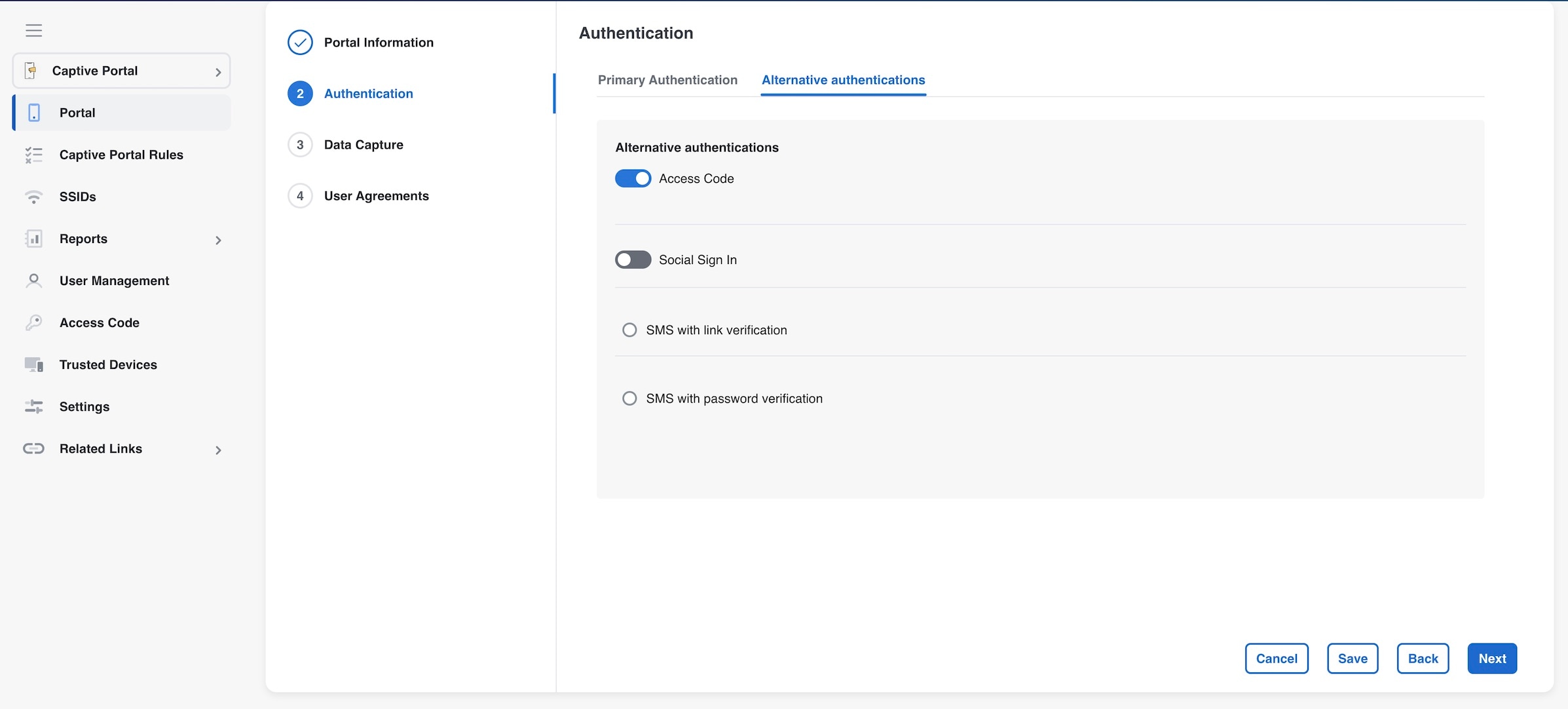
In the Alternate Authentication window, users can select other authentications such as Access Code and Social Sign in. In addition to these two, SMS with link verification and SMS with password verification are also available. Only one of these SMS options can be selected at a time using the radio button support.

Note


For the Social Sign In authentication option, users can choose from three options: Facebook, Twitter, and LinkedIn.

Step 5

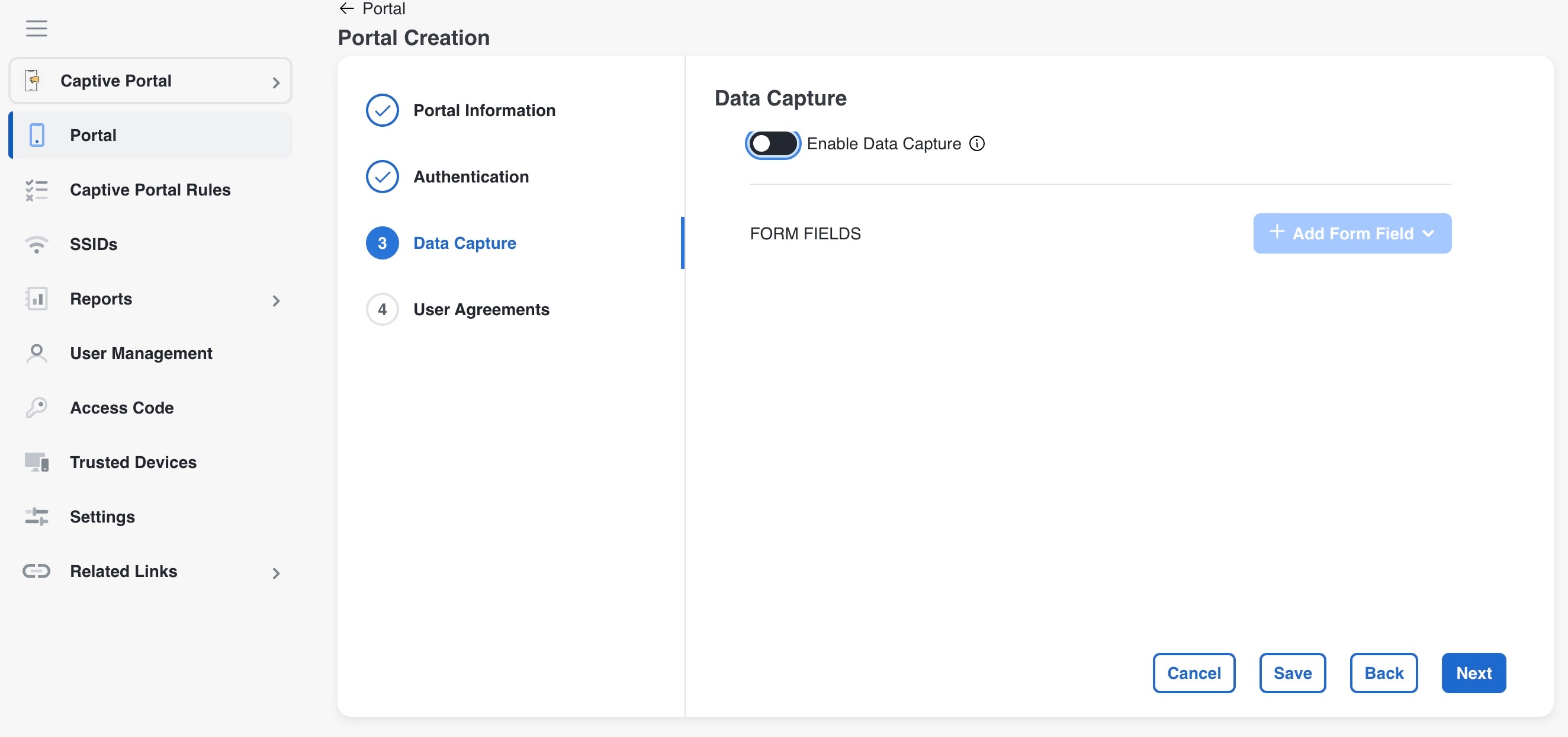
If you want to add Data Capture form for this portal, check the Enable Data Capture check box. Configure the Data Capture form. Add the fields required for the Data Capture form using the +Add Form Field button. For more information on adding fields to the Data Capture form, refer to the Add a data capture form to a portal.
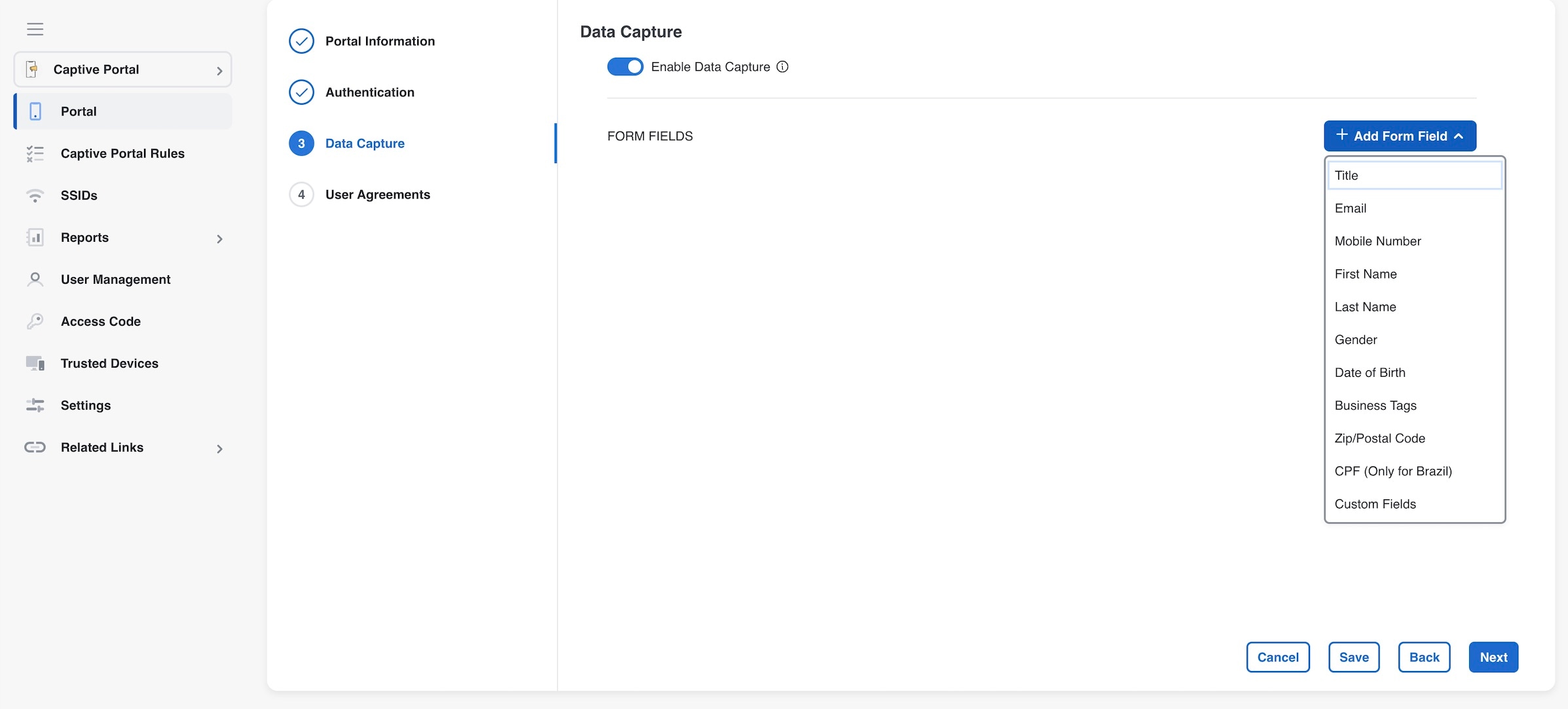
 Click Next.

The User Agreements window appears.

Step 6

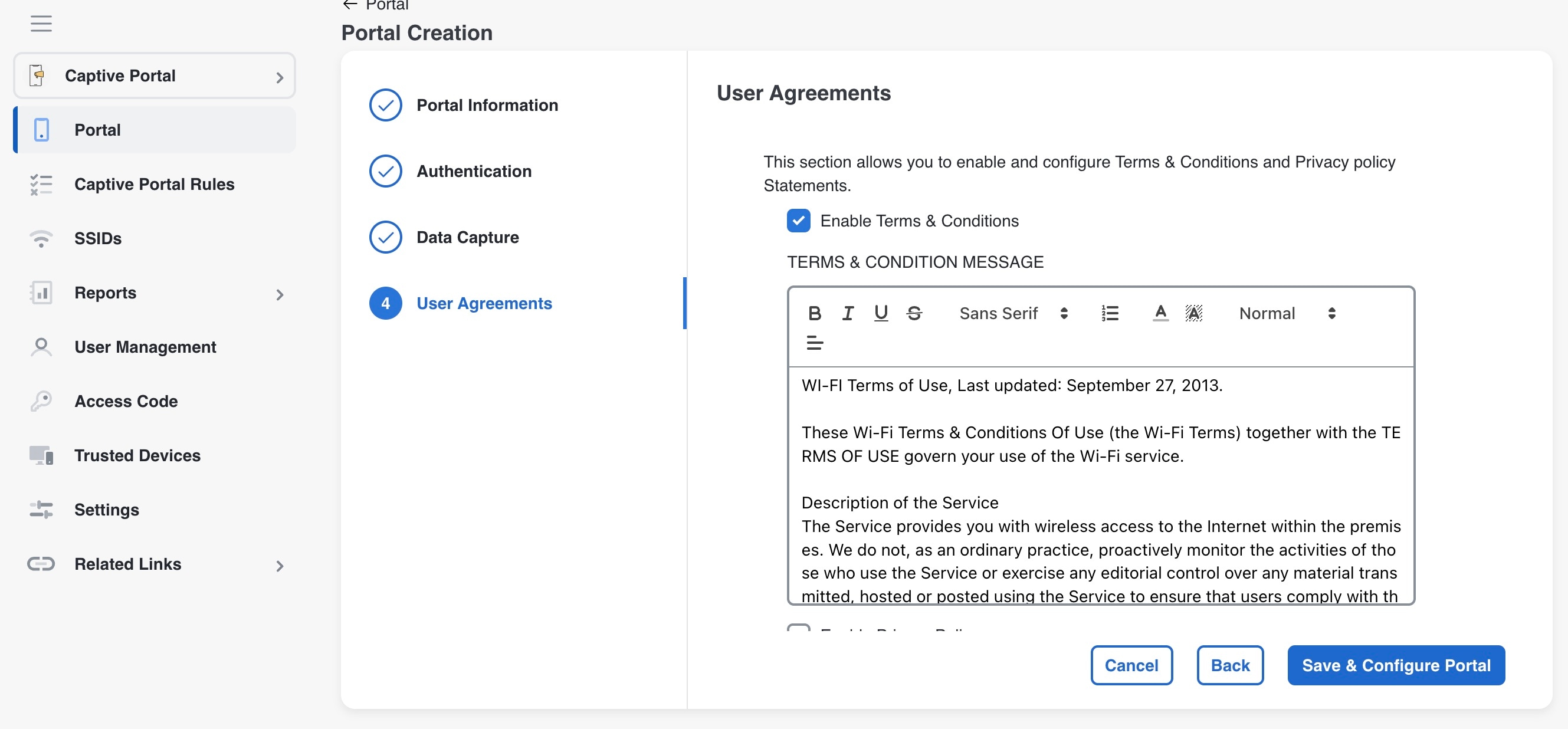
In the Terms & Condition Message field, enter the Terms & Conditions for the portal. If you want to display privacy policy along with the Terms & Conditions, check the Enable Privacy Policy check box, and in the Privacy Policy field that appears, enter the privacy policy.

Note

 
By default, the Enable Terms & Conditions check box is checked. If you do not want to specify any Terms & Conditions, uncheck the Enable Terms & Conditions check box.

If you specify the privacy policy, during customer acquisition, the privacy policy also appears along with the Terms & Conditions.

Step 7

From the How frequently do you want users to accept agreements drop-down list, select the frequency at which the customer must accept the Terms & Conditions to access the internet. In the User Accepts Terms In area, choose how the Terms & Conditions must appear during customer acquisition.

  • 1-Click: Choose this option, if you want display only the Terms & Conditions link. If you select this option, during customer acquisition, the customer can proceed further by clicking the Terms & Conditions button.

  • 2-Click: Choose this option, if you want to display a check box also along with the Terms & Conditions link. If you select this option, during customer acquisition, the customer has to select the check box, and click the Accept Terms and Continue button to proceed further.

Note

 
The 2-Click option is provided in Cisco Spaces to meet the legal requirements of certain countries.

Step 8

If you want to restrict the internet access to the customers below certain age, select the Enable Age gating check box, and then choose the required age gating method from these:

  • Moderate: If you choose this option, during customer acquisition, the customer has to acknowledge that the age is 16 or above to proceed further.

  • Strict: If you choose this option, during customer acquisition, the customer has to specify the month and year of the birth to access the internet. If the customer provides the age as less than 16, an alert message is shown, and the customer cannot proceed further to access the internet. However, the customer will be provided an option to change the age, if required.

Click Save and Configure Portal.

A message Portal saved successfully appears, and the Portal window opens with the portal modules on the left and portal preview on the right.

Step 9

Add features to the portal using the Portal modules. Click Save to save the changes made to each module.

Note

 
When creating the portal, you can save the portal after specifying the name and locations for the portal. The new portal gets listed in the Portals window. You can configure authentication type, Terms & Conditions, Data Capture form, and so on at any time later using the Edit Portal button for that portal.

Note

 
To capture the details such as name, phone number, and so on of the customers connecting to the SSID using the captive portal, ensure that you add a “Data Capture form” in the captive portal. During customer acquisition (runtime), before provisioning the internet, the data capture form is displayed to the customer. The captured customer details are stored in Cisco Spaces.

Note

 
A portal becomes live when you associate it with a Captive Portal Rule, and publish that rule.

Portal modules

These are the portal modules of Cisco Spaces:

  • Header/Branding: Define your page title and brand name in the portal using this module.

    Use the Page Title field to modify the captive portal page title. The updated Page Title is displayed in your Cisco Spaces: Captive Portal app. You can add the brand name as text or a logo image.

  • Welcome Message: Add a welcome message in the portal using this module. You can configure the portal to show different welcome messages for first-time users and repeat users.

  • Notice: Add a notice in the portal using this module. This helps you display notices to the portal users whenever required. You can choose to provide the notice in thicker text, plain text, or text with an image format.

  • Authentication: Based on the authentication type selected when creating the portal, an Authentication module appears for the portal. The name of the module will be based on the authentication type. For example, if you have selected SMS with link verification as authentication type for a portal, the authentication module for that portal will be named as SMS Authentication. The Authentication module provide how to configure the landing page URL for the portal. The Authentication module is not available for the authentication type, No Authentication, if both Data Capture and User Agreements are not enabled.

  • Venue Map: Add a label and icon for the Venue Map using this module. The venue map is uploaded in the portal from your wireless network based on the location.

  • Videos: Add YouTube videos in the portal using this module. You can also add an appropriate caption and icon for the video section in the portal. You can also view the preview of the video when uploading.

  • Feedback: Add the feedback questions in the portal using this module. You can add multiple choice and rating questions. This module also lets you customize the labels for the Submit button, Thank You message, and Post Submission button. You can enable a text box for customers to add comments. You can also specify the e-mail addresses and subject for feedback.

  • Help: Add a help line number that the customer can contact for assistance using this module. You can customize the caption and icon for Help.

  • Get Apps: Add apps to the portal using this module. You can add appropriate caption and icon for each app using this module.

  • Get Internet: Add the external URL to which customer can navigate from the Get Internet section in the portal. To navigate to this URL, the customer has to accept the terms and conditions provided.

  • Promotions and Offers: Add the promotions and offers to display through the portal using this module. You can modify the title of the promotion. For each promotion, you can add appropriate captions and images and specify the URL to the promotion details. Promotions are displayed as carousels.

  • Add Module: Add customized content and menu items to the portal using this module. All the modules mentioned earlier are the default modules provided by Cisco Spaces. You can add additional items to a portal based on your requirements using the Add Module button.

Configure a language for a portal

Enable your portal to display module captions and static content in a language other than English.

In Cisco Spaces, you can configure the language in which the module captions and static content in the portal are to display. To display static content in a language other than English, upload the corresponding text to Cisco Spaces. Cisco Spaces does not support entering content directly in languages other than English. By default, the language is set to English, but you can change this setting.


Note


Cisco Spaces does not provide a content translation feature.

To configure the display language for portal content, complete these steps.

Procedure


Step 1

To show static content, such as messages and country names, in a language other than English, upload the key values in the desired language. For more details on uploading key values for a language, refer to the Upload static content key values for a language.

Step 2

Open the portal where you want to configure the language.

Step 3

Click the Languages icon at the top of the Portal window.

The Add Language window appears.

Step 4

Click Add Language.

Step 5

In the search field, enter the language.

If Cisco Spaces supports this language, the name appears in the drop-down list.

Step 6

Click the Add button next to the language name.

The language gets added to the Added Languages list.

Step 7

Click Add.

A drop-down list now appears next to the Languages icon in the portal, showing the newly added language.

Step 8

From this list, select the language for displaying static portal content.

The captions of the modules are displayed in the chosen language.


Set a default language

Ensure users view the portal in a consistent language of your choosing.

To set a default language, do the following:

Procedure

Step 1

In the portal, click the Languages icon at the top right of the window.

Step 2

In the Add Language window, from the “Default Language” drop-down list, select the default language.

Step 3

Click Add.


Upload static content key values for a language

Enable the portal to present all standard interface messages in a language other than English by uploading a template containing the translated key values.

To set to display the static content in any language other than English, perform these steps:

Procedure

Step 1

In the portal, click the Languages icon at the top right of the window.

Step 2

In the Add Language window, click Download to download and save the template.

Step 3

Open the template.

The template contains keys for various static messages. It also includes the message that appears if your language is English. The column for English has “en” as first row.

Step 4

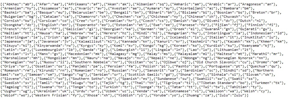
In the column next to the English column, enter the identifier for the language you want to use for the static content.

For example, to display content in Arabic, enter “AR” in the first row.

Step 5

Enter the text for each key in the remaining rows.

Step 6

Save the file.

Step 7

In the Add Language window, click Upload.

Step 8

Click Add.


What to do next

To know how to display the static content in a language, refer to the Configure a language for a portal.

The language code for various languages are shown in this figure.

Figure 1. Language Code

Configure authentication for a portal

To secure your portal from hacking or misuse, you can configure various authentication options for your portal. The customer is granted access only if authentication succeeds.

You can authenticate the internet provisioning through SMS, e-mail, access code, or social networks such as Facebook, Twitter, or LinkedIn. Cisco Spaces supports the SMS gateway of the third party vendors for SMS authentication. You can configure to provide SMS authentication through “SMS with password verification” or “SMS with link verification”. For “SMS with password verification”, you can define a custom verification code for a portal or you can configure to auto-generate the verification code.

During customer acquisition, the authentication process is initiated when the customer click any menu item in the portal. However, you can configure for inline authentication also, so that the Authentication module will be shown in the captive portal. For more information on inline authentication, refer to the Inline authentication.

Cisco Spaces supports these authentication types:

  • SMS with password verification: For this authentication type, validation of mobile number is mandatory. When the customer enters a valid mobile number, an SMS is sent to that mobile number, which contains a link and verification code. The customer can access the internet by providing the verification code in the SMS. The customer is not allowed to proceed further until the verification code is entered. Some use cases for this authentication type are SMS-based engagement campaigns, country specific requirements to verify the users connecting to internet, and so on. To know the authentication steps during customer acquisition, refer to the Steps for SMS with password verification authentication. For more information on configuring the “SMS with password verification”, refer to the Configure a portal for SMS with password verification section.

    SMS with link verification: For this authentication type, validation of mobile number is optional. When the customer provides a valid mobile number, an SMS is sent to that mobile number with verification link. The customer can complete the validation by clicking the verification link in the SMS. However, customer can skip the validation process and proceed further. This authentication type can be used if the validation of the mobile number is not mandatory . To know the authentication steps during customer acquisition, refer to the Steps for SMS with link verification authentication. For more information, refer to the Configure a portal for SMS with link verification section.

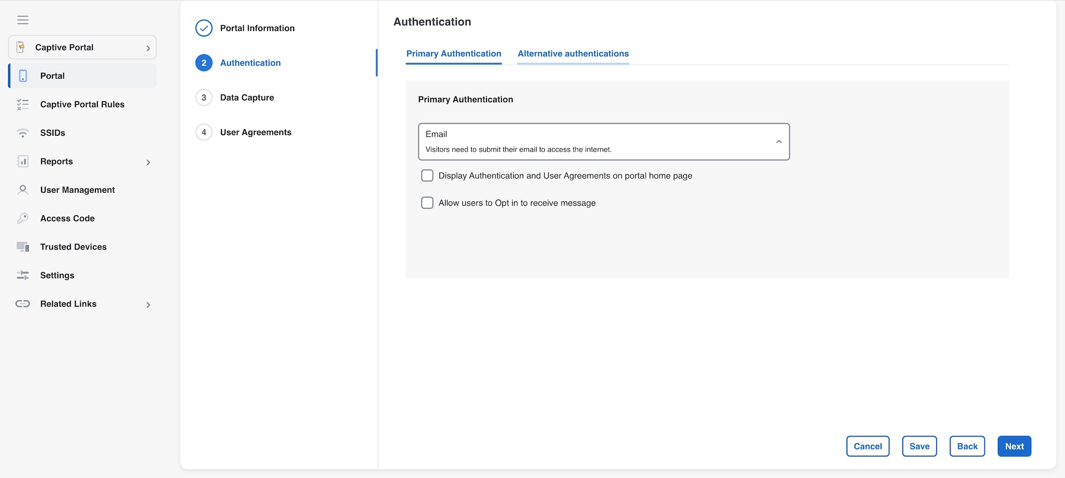
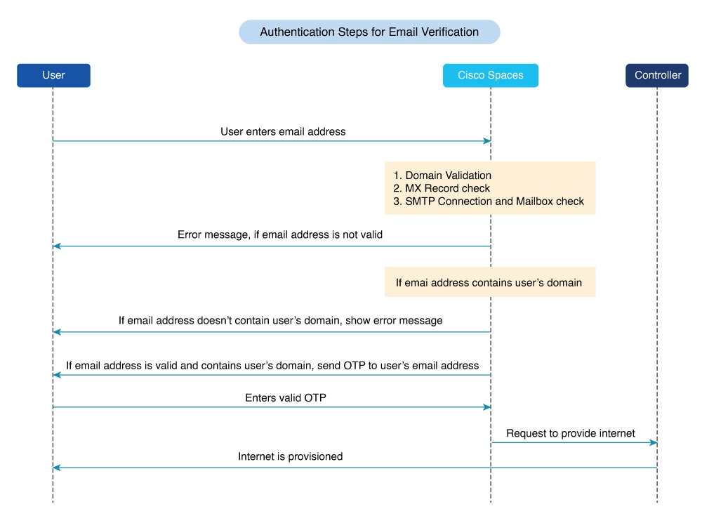
    Email: The customer has to provide a valid e-mail ID to access the internet. To know the authentication steps during customer acquisition, refer to the Steps for E-mail authentication. For more information on configuring e-mail authentication, refer to the Configure a portal for E-mail authentication section.

    Social Sign In: The internet access is provided only if the customer is logged in to a social site configured for authentication. You must configure at least one social site to use this option. To know the authentication steps during customer acquisition, refer to the Steps for social authentication. For more information on configuring the Social Sign In authentication, refer to the Configuring a Portal for Social Sign In Authentication section.

    Access Code: The customer has to provide a valid access code to access the internet. To know the authentication steps during customer acquisition, refer to Steps for access code authentication. For more information on configuring Access code authentication, refer to the Configure a portal for access code authentication section.

    No Authentication: The internet access is provided without any authentication process. To know the authentication steps during customer acquisition, refer to Steps for no authentication with terms and conditions. For more information on configuring a portal for No Authentication, refer to the Configure a portal with no authentication section.


Note


The Opt In option is not available for the "Social Sign In" authentication type. You can configure the Data Capture form for all the authentication types, except “Social Sign In”. For more information on configuring the Data Capture form, refer to the Add a data capture form to a portal. For more information on Opt In feature, refer to the “Opted In Option for Users” section.

Note


For SMS with link verification and SMS with password verification, you can include additional information that needs to be passed to the SMS gateways. For example, if you want to send the SMS in a language other than English to your customers, provision is now available to include that information in the SMS sent to the SMS Gateways.


Configure a portal for SMS with link verification

Enable customers to receive a secure access link via SMS for captive portal authentication, and manage SMS notification opt-in preferences.

To configure a portal for “SMS with link verification”, do these:

Procedure

Step 1

When creating a portal, from the Authentication Type drop-down list, select SMS with Link verification.

Step 2

If you want to configure inline authentication for this portal, and display the “Data Capture form” and “User Agreements” in the home page, check the Display Authentication, Data Capture, and User Agreements on portal home page check box. For more information on inline authentication, refer to the Inline authentication.

Step 3

If you want the customers to provide an option to opt for receiving notifications, check the “Allow users to Opt in to receive message” check box.

Step 4

If the “Allow users to Opt in to receive message” check box is checked, these fields appear:

  • Opt in Message: Enter an opt in message.

  • Default Opt-In Check Box Behavior

    • Checked: Click this option if you want the OptIn check box to be displayed as checked by default, during customer acquisition.

    • Unchecked: Click this option if you want the OptIn check box to be displayed as unchecked by default, during customer acquisition.

Step 5

In the SMS Text field, enter the text message that must appear in the SMS sent to the customer.

Note

 
To display the link through which the customer can access the captive portal, ensure that “{Link}” is not removed when editing the text message.

Step 6

From the Default Country drop-down list, select the country for which this setting is applicable.

Step 7

From the SMS Gateway drop-down list, select the SMS gateway.

The SMS Gateways configured in the Settings option are available for selection. You can also use the Demo Gateway provided by Cisco that is chargeable.

Note

 
For more information on configuring the SMS gateway, refer to the Configure an SMS gateway in Cisco Spaces.

Step 8

Save the changes.


What to do next


Note


Portals with SMS with link verification authentication type will have an authentication module named SMS Authentication. For more information on the Authentication Module, refer to the Authentication module.

Note


If you have not configured the authentication type when creating the portal, you can specify it at any time using the Edit Portal button for that portal in the Portals window.

Configure a portal for SMS with password verification

Set up a portal that authenticates users using SMS messages with password verification.

To configure a portal for “SMS with password verification”, perform these steps:

Procedure

Step 1

When creating a portal, from the Authentication Type drop-down list, select SMS with password verification.

Step 2

If you want to configure inline authentication for this portal, and display user agreements on portal home page, check the Display Authentication and User Agreements on portal home page check box. For more information on inline authentication, refer to the Inline authentication.

Step 3

If you want the customers to provide an option to opt for receiving notifications, check the “Allow users to Opt in to receive message” check box.

Step 4

If the “Allow users to Opt in to receive message” check box is checked, these fields appear:

  • Opt in Message: Enter an opt in message.

  • Default Opt-In Check Box Behavior

    • Checked: Click this option if you want the OptIn check box to be displayed as checked by default, during customer acquisition.

    • Unchecked: Click this option if you want the OptIn check box to be displayed as unchecked by default, during customer acquisition.

Step 5

Click the required Password Type.

  • Auto Generated password: To auto-generate the password for each authentication request. The auto-generated password is sent to the customer.

  • Fixed Password: To define a password for authentication. For all of the customers, this password is sent whenever there is an authentication request. In the “Password” field that appears when you click the “Fixed Password” option, enter the password that is to send to the customers.

Step 6

In the SMS field field, enter the text that must appear in the SMS that is sent to the customer.

Note

 
To display the link through which the customer can access the captive portal, ensure that “{Link}” is not removed when editing the text message. Similarly, to display the password in the message, ensure that the “{Password}” is not removed.

Step 7

From the Default Country drop-down list, select the country for which this setting is applicable.

Step 8

From the SMS Gateway drop-down list, select the SMS Gateway.

The SMS Gateways configured in the Settings option are available for selection. You can also use the Demo Gateway provided by Cisco that is chargeable.

Note

 
The SMS Gateway window appears where you can configure the required SMS gateway. For more information on configuring the SMS gateway, refer to the Configure an SMS gateway in Cisco Spaces.

Step 9

Save the changes.


What to do next


Note


Portals with SMS with password verification authentication type will have an authentication module named SMS Authentication. For more information on the Authentication module, refer to the Authentication module.

Note


If you have not configured the authentication type when creating the portal, you can specify it at any time using the Edit Portal button for that portal in the Portals window.

Configure a portal for social sign in authentication

Allow users to access the internet through a captive portal using social network credentials.

Cisco Spaces supports authentication through these social networks:

  • Facebook

  • Twitter

  • LinkedIn


Note


To authenticate the access to the internet through a social network, you must configure the app for that social network in Cisco Spaces. You can configure the social app in Cisco Spaces through the Settings option. For more information, refer to the Add social apps for social authentication.


To authenticate the access to a portal through social sign in, perform these steps:

Procedure

Step 1

When creating a portal, from the Authentication Type drop-down list, select Social Sign In.

The social networks that are supported by Cisco Spaces for authentication appear along with the configured social apps.

Step 2

If you want to configure inline authentication for this portal, and display user agreements in the portal home page, check the Display Authentication and Users Agreements on portal home page check box. For more information on inline authentication, refer to the Inline authentication.

Step 3

Check the check box adjacent to the social networks through which you want to authenticate access to the internet.

The social networks configured in the Social Apps option under the Settings section will be available for selection. For more information on configuring the Social Apps, refer to the Add social apps for social authentication.

Step 4

Save the changes.


What to do next

  • Portals with Social Sign In authentication type will have an authentication module named Social Authentication. For more information on the Authentication Module, refer to the Authentication module.

  • The +Add button takes you to the Social Apps window where you can configure the customized apps.

  • If you have not configured the authentication type when creating the portal, you can specify it at any time using the Edit Portal button for that portal in the Portals window.

Configure a portal for E-mail authentication

Enable customers to authenticate through email on the portal and optionally opt in to receive notifications.

To configure a portal for e-mail authentication, do these:

Procedure

Step 1

When creating a portal, from the Authentication Type drop-down list, select Email.

Step 2

If you want to configure inline authentication for this portal, check the Display Authentication and User Agreements on portal home page check box. For more information on inline authentication, refer to the Inline authentication.

Step 3

If you want to provide the customer an option to opt for receiving notifications, check the Allow users to Opt in to receive message check box.

Step 4

If the Allow users to Opt in to receive message check box is checked, these fields appear:

  • Opt in Message: Enter an “opt in” message

    .
  • Default Opt-In Check Box Behavior

    • Checked: Click this option if you want the Opt In check box to be displayed as checked by default, during customer acquisition.

    • Unchecked: Click this option if you want the Opt In check box to be displayed as unchecked by default, during customer acquisition.

Step 5

Save the changes.


What to do next


Note


Portals with Email authentication type will have an authentication module named Email. For more information on the Authentication Module, refer to the Authentication module.

Configure a portal for access code authentication

Set up a portal that authenticates users with access codes and allows users to opt in to receive messages, display authentication inline, and present user agreements.

To configure a portal for the Access Code authentication, do these:

Procedure

Step 1

When creating a portal, from the Authentication Type drop-down list, select Access Code.

Step 2

If you want to configure inline authentication for this portal, and display user agreements on portal home page, check the Display Authentication and User Agreements on portal home page check box. For more information on inline authentication, refer to the Inline authentication.

Step 3

If you want the customers to provide an option to opt for receiving notifications, check the Allow users to Opt in to receive message check box.

Step 4

If the Allow users to Opt in to receive message check box is checked, these fields appear:

  • Opt in Message: Enter an opt in message.

  • Default Opt-In Check Box Behavior

    • Checked: Click this option if you want the Opt In check box to be displayed as checked by default, during customer acquisition.

    • Unchecked: Click this option if you want the Opt In check box to be displayed as unchecked by default, during customer acquisition.

Step 5

Save the changes.

You can create access codes and share it with your customers using the Access Code option displayed in the left pane of the Captive Portals app. For more information on creating and sharing the access codes, refer to the Access codes.


What to do next


Note


Portals with Access Code authentication type, provided Data Capture or User Agreements is enabled. For more information on the Authentication module, refer to the Authentication module.

Configure a portal with no authentication

Allow users to access the portal without authentication while providing options for data collection, agreements, and notification preferences.

To configure a portal for No Authentication, perform these steps:

Procedure

Step 1

When creating a portal, from the Authentication Type drop-down list, select No Authentication.

Step 2

If you want to display data capture and user agreements on portal home page, check the Display Data Capture and User Agreements on portal home page check box.

Step 3

If you want the customers to provide an option to opt for receiving notifications, check the Allow users to Opt in to receive message check box.

Step 4

If the Allow users to Opt in to receive message check box is checked, these fields appear:

  • Opt in Message: Enter an “opt in” message.

  • Default Opt-In Check Box Behavior

    • Checked: Click this option if you want the Opt In check box to be displayed as checked by default, during customer acquisition.

    • Unchecked: Click this option if you want the Opt In check box to be displayed as unchecked by default, during customer acquisition.

Step 5

Save the changes.


Inline authentication

A captive portal inline authentication is a user authentication method that

  • displays the authentication module before the user clicks any link on the portal

  • reduces the number of steps required for users to initiate authentication, and

  • supports multiple authentication types, including SMS with verification, email, and social authentication.

To configure inline authentication, select the check box for inline authentication on the Authentication screen.

For the SMS with Link verification and SMS with password verification authentication types, the authentication section includes a field for entering the mobile number and a Connect button. For Email authentication, the authentication section includes a field to enter the email address. For social authentication, the authentication section provides buttons for each social network configured for the portal. Customers can complete authentication by selecting the appropriate social network.

Authentication module

When you select the authentication type for a portal, the system creates an authentication module for that portal based on the selected type.

However, if you select No Authentication or Access Code, and either Data Capture or User Agreements is not enabled, the portal will not have an authentication module.

The authentication module includes a field to specify an alternate landing page for the portal.

Add a data capture form to a portal

To set up a form in the captive portal that collects customer information and business tags for improved user identification and filtering.

If you choose an authentication type other than Social Sign In for the portal, you can add a Data Capture form in the captive portal. You can add fields to the Data Capture form when creating the portal. These fields can capture customer details, such as first name, last name, mobile number, and other information. You can also add business tags based on which you can filter your customers.


Note


The business tags defined in the Data Capture form are accessible in the “Add Tags” option used in rules such as Captive Portal Rule, Engagement Rule, and Profile Rule.

To configure a Data Capture form in a captive portal, perform these steps:

Procedure


Step 1

When creating a portal, after specifying the Terms and Conditions, click Next.

The Data Capture screen appears.

Step 2

Enable the Data Capture check box.

Step 3

Click Add Form Field.

You can add these field elements to the Data Capture form:

  • Title: To specify how to address the customer. For example, Mr, Ms. If you configure this field, during customer acquisition (runtime), the titles, Mr and Ms will be available for selection in the Data Capture form for the customer.

  • Email: To specify the e-mail ID of the customer.

  • Mobile Number: To specify the mobile number of the customer. You can specify a default country for the mobile number so that during customer acquisition, the code for the default country is displayed in the data capture form.

  • First Name and Last Name: To specify the first and last name of the customer.

  • Gender: To specify the gender of the customer.

  • Date of Birth: To specify the date of birth of the customer. If you add the Date of Birth field, you are not allowed to select the Moderate option in the Enable Age Gating area in the User Agreements window.

  • Business Tags: To provide an answer of customer’s choice for the business tag question. These business tags help you in categorizing the customers.

  • Country Specific Fields

    • ZIP/Postal Code: To provide the postal code of your address.

    • CPF: To provide the CPF (This is applicable only for Brazil).

  • Custom Fields: To help the user create their own fields such as Plain Text, Dropdown, Check Box, Radio button and Date Picker.

    • Plain Text and Date Picker: Add the Field Name, Label, and Placeholder.

    • Dropdown, Check Box and Radio Button: Add the Field Name, Label and if required you can make this field mandatory by checking the Make this field mandatory checkbox.

      Note


      Although there are five field types, users can add a maximum of three fields at one time in the portal. These fields can all be the same type or different types, depending on the user's preference.

Note

 
The Email field element is not available for Email authentication as the e-mail information is already collected during authentication. The Mobile Number field element is not available for the SMS with password verification authentication as the customer has to provide the mobile number during authentication.

Step 4

Click the corresponding option to add the fields.

General Fields

  • In the Place Holder field, enter the text that must appear as placeholder for the field.

  • Check the Make this field mandatory check box to make the field mandatory.

Element-Specific Fields

  • For the mobile number field element, choose the default country so that the country code for this country appears in the data capture form during customer acquisition.

  • For the Zip/Postal Code field element, from the Country drop-down list, select the country, so that the data capture form allows the customer to add the postal codes of that particular country. To support the postal codes of more than one country, click Add Country, and add another country.

  • For the Business Tag field element, you must configure these additional fields:

    • In the Name field, enter a name for the business tag.

    • In the Field label field, enter the question that you want to ask the customer.

    • Click +Add Option.

    • In the field that appears, enter an answer that you want to provide to the customers to opt.

    • Similarly, add the remaining answer choices also using the +Add Option.

Note

 
You can delete an added option using the corresponding Delete icon.

Note

 
When the customers access the Data Capture form during authentication process, the answers you specify are available in a drop-down list. They can choose the required value. You can use this value for filtering the customers in the proximity rules.

Step 5

Save the changes.

Note


During customer acquisition, the value entered in the CPF field in the Data Capture form will be converted to the "000.000.000-00" format. The number will be formatted automatically as the user enters the CPF number value. So the captive portal users do not have to add dots or hyphen manually to maintain the required format.


Define a brand name for a portal

Set up branding for a portal so users see your company name or logo and the appropriate page title when they access it.

Cisco Spaces enables you to add your brand name and page title in the portal using the Header/Branding module. You can add the brand name as text or image. For example, you can use your company logo as a brand name.

To define a brand name and page title in the portal, perform these steps:

Procedure


Step 1

Open the portal for which you want to define the brand name.

Step 2

Click the Header/Branding module.

Step 3

In the Page Title field, edit the page title.
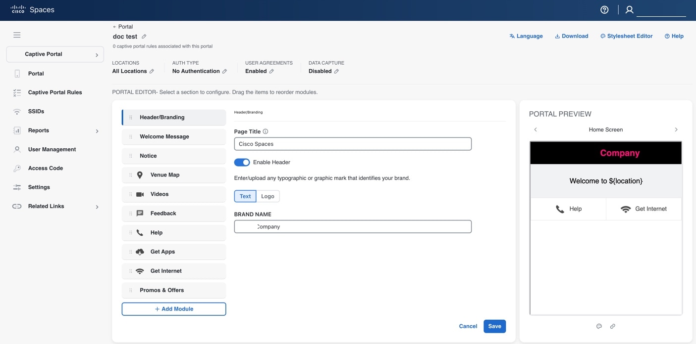
Figure 2. Header/Branding Module

Note

 
  • The page title for existing portals defaults to Cisco Spaces. For all new portals created, the account name serves as the default page title. You can edit the page title.

  • This feature is only available in the Cisco Spaces beta UI.

Step 4

Click Enable Header to view the portal preview.

Step 5

Choose the type of brand.

  1. If you choose Text only, enter the Brand Name in the field that appears.

  2. If you choose Logo, click the Upload button that appears, and upload the logo image.

Step 6

Click Save.

The brand name and page title for the portal are defined.


What to do next


Note


If you are modifying a portal that is already associated with a published captive portal, click the Save & Publish button to immediately publish the changes. The Save & Publish button appears only if the portal is associated with a captive portal rule. For more information on creating a captive portal rule, refer to the Create a captive portal rule to display captive portals .


Add a welcome message to a portal

Enable tailored welcome messages in your portal to increase engagement for new and repeat visitors.

Add a welcome message to your portal using the Welcome module. The welcome message displays when a customer accesses your portal. Configure the portal to display different welcome messages for first-time and repeat users.

To add a welcome message to a portal, perform these steps:

Procedure


Step 1

Open the portal in which you need to add the welcome message.

Step 2

Click the Welcome Message module.

The Welcome Message window appears.

Step 3

In the First time visitor welcome text field, enter the welcome message that must appear when a customer accesses your portal for the first time. You can include the location details using the smart link variables. For more information on smart link, refer to the Smart links and text variables for Captive Portals.

Step 4

To display a different welcome message for repeat users, check the Add a custom message for Repeat Visitors check box. Add a custom message for Repeat Visitors check box. Enter the welcome message for repeat users in the adjacent text box. You can include the name and location details using the smart link variables. The variables 'firstName' and 'lastName' are available only if you configure a Data Capture module in the portal with the fields First Name and Last Name. 'firstName' and 'lastName' are available for authentication types except 'Social Sign In'. For more information on smart link, refer to the Smart links and text variables for Captive Portals.

Step 5

Click Save.

The welcome message is successfully defined for the portal.


What to do next


Note


If the portal is associated with a published captive portal, click Save and Publish button to publish the changes. Save and Publish button appears only when the portal is associated with a captive portal rule. For more information on creating a captive portal rule, refer to the Create a captive portal rule to display captive portals .

Add a notice to a portal

Add a ticker, text, or image notice for portal users to receive important updates and announcements.

The Notice module allows you to provide notices in your portal. This module is useful when you want to pass any important information to your customers. You can add ticker notices, text notices, and images with text notices.

You can configure the date up to which the notice is to be displayed in the portal.

To add notices in a portal from the dashboard, follow these steps:

Procedure


Step 1

Open the portal where you want to add a notice.

Step 2

Click the Notice module.

The Notice window appears.

Step 3

Click the type of notice you want. These options are available:

  • Ticker Text Only: The notice appears in a moving text format. For Ticker Text Only, in the Notice field that appears, enter the notice text.

  • Text Only: The notice appears in the text format. For Text Only, in the Notice field that appears, enter the notice text.

  • Text with Image: The notice appears as a text along with an uploaded image. For Text with Image, do these:

    • In the Notice field, enter the notice text.

    • In the Notice image area, click the Upload button, upload the image to display with the notice.

Step 4

In the Hide After field, choose the date up to which the notice is to display in the portal.

Step 5

Click Save .

The notice is successfully added to the portal.


What to do next


Note


If you are modifying a portal that is already associated with a published captive portal, click the Save and Publish button to immediately publish the changes. The Save and Publish button appears only if the portal is associated with a captive portal rule. For more information on creating a captive portal rule, refer to the Create a captive portal rule to display captive portals .

Provide the venue details in a portal

Enable users to view venue details such as label, icon, and wireless map in a portal.

You can provide the venue details in a portal using the Venue Map module. You can define a label name, upload an icon image, and display a map for the venue using this module.

The default name of the module is Venue Map, but the module name changes when you edit the Label field.

To add the venue details for a portal, perform these steps:

Procedure


Step 1

Open the portal where you want to add venue details.

Step 2

Click the Venue Map module.

The VENUE MAP window appears.

Step 3

In the Label field, enter the venue map label name to display in the portal.

Note

 
The Venuw Map module name gets changed to the name you specify in the Label field.

Step 4

In the Logo area, upload the map icon to appear next to the map label. You can drag or click the Upload button.

Note

 
To remove an icon, click the Delete icon.

Step 5

In the Store Map area, the map for this venue as in the wireless network appears.

Note

 
The map only appears if the portal is associated with a location that has a map defined in the wireless network (CUWN or Meraki). The map for the customer's current location is shown.

Step 6

Click Save.

The venue map is configured for the portal.


What to do next


Note


If you are modifying a portal that is already associated with a published captive portal, click the Save and Publish button to immediately publish the changes. The Save and Publish button appears only if the portal is associated with a captive portal rule. For more information on creating a captive portal rule, refer to the Create a captive portal rule to display captive portals .

Upload videos to a portal

Administrators can add YouTube videos to portal pages for end users.

You can upload the videos to Cisco Spaces portals using the videos module. In this module, you can add a label and an image for the area where the video appears in the portal and specify the YouTube URL of the video.

The default name of the module is videos. The module name changes according to the value you enter in the Label field.


Note


You can show only YouTube videos in your portal.

To upload videos to a portal, perform these steps:

Procedure


Step 1

Open the portal in which you want to upload the video.

Step 2

Click the Videos module.

The VIDEOS window appears.

Step 3

In the Label field, enter the label that appears for the area where the video displays in the portal.

Note

 
The Videos module name changes to the name you specify in the Label field.

Step 4

In the Logo area, upload the video icon adjacent to the video label. You can drag or click the Upload button.

Note

 
You can delete the icon using the Delete icon.

Step 5

In the YouTube URL field, enter the YouTube URL of the video that you want to display in the portal.

Step 6

Click Save.

The video is successfully uploaded to the portal.


What to do next


Note


If you modify a portal that is associated with a published captive portal, click the Save and Publish button to publish your changes. The Save and Publish button is available only if the portal is associated with a captive portal rule. For more information on creating a captive portal rule, refer to the Create a captive portal rule to display captive portals .

Provide a feedback section in a portal

Allow portal customers to submit structured feedback, such as ratings, multiple-choice responses, and text comments, directly within Cisco Spaces.

The Feedback module enables you to collect feedback from your portal customers. This module lets you add multiple questions to the feedback section. You can configure questions with multiple-choice answers or rating-based answers. You can also provide a text box for customers to add comments.

To add a feedback section in a portal, perform these steps:

Procedure


Step 1

Open the portal where you want to add the feedback section. Click the Feedback module.

The FEEDBACK window appears.

Step 2

In the Label field, enter a name to display for the feedback section. In the Icon area, upload an icon image that appears next to the feedback label. You can drag or click the Upload button.

Step 3

In the Question field, enter a question for which you want the answer from the customer. In the Question Image area, upload an image that must appear adjacent to the question using the Upload button.

Step 4

In the Question Type area, select a question type:

  • Rating: The customer answers the question using a rating scale.

  • Multiple Choice: The customer selects from provided choices. If you choose this option, enter answer choices in the Option 1 and Option 2 fields. To add more choices, use the 'Add option' button.

Note

 
You can add additional questions to the feedback section using the 'Add question' button.

Step 5

In the Submit Button Label field, enter the name for the submit button, using which the customer must submit the answer. In the Thank You/Success message field, enter the message shown to customers after they submit their answer.

Step 6

In the Post Submission button label field, enter the name for the button that appears after submission. This button takes the customer to the Cisco Spaces dashboard. If you want to provide a text box for the customer to enter the comments, select the Add a text box for additional comments from end user? check box.

Step 7

In the Email to field, enter the destination email address for feedback.

Step 8

In the Email from field, enter the From e-mail address to display to the receiver of the e-mail for the feedback e-mails.

Step 9

In the Email Subject field, enter the subject line for feedback emails. Click Save.

The feedback section is successfully created in the portal.


What to do next


Note


If you are modifying a portal that is linked to a published captive portal, click the Save and Publish button to to apply your changes immediately. The Save and Publish button appears only if the portal uses a captive portal rule. For more information on creating a captive portal rule, refer to the Create a captive portal rule to display captive portals.

Add a help option to a portal

Enable users to quickly access help and support within your Cisco Spaces portal.

You can add a helpline in your Cisco Spaces portal using the Help module. Customers can use this helpline to contact you if they need assistance. In this module, you can add a label and image for the area where the helpline appears in the portal. You can also specify the contact number for assistance.

The default name of the module is Help. The module name updates based on the value you enter in the Label field.

To add a Help option to a portal, perform the steps:

Procedure


Step 1

Open the portal in which you need to add a help option.

Step 2

Click the Help module.

The HELP window appears.

Step 3

In the Label field, enter the label that must appear for the area where the helpline appears in the portal.

Note

 
The Help module name gets changed to the name you specify in the Label field.

Step 4

In the Icon area, upload the help icon that must appear adjacent to the help label. You can drag or click the Upload button.

Note

 
You can delete the icon using the Delete icon.

Step 5

In the Contact field, enter the help line number.

Step 6

Click Save .

The help option is successfully defined for the portal.


What to do next


Note


If you are modifying a portal that is already associated with a published captive portal, click the Save and Publish button to immediately publish the changes. The Save and Publish button appears only if the portal is associated with a captive portal rule. For more information on creating a captive portal rule, refer to the Create a captive portal rule to display captive portals .

Add apps to a portal

Add applications for users to access through your Cisco Spaces portal.

You can add applications to your Cisco Spaces portal using the Apps module, which supports apps from both the iOS App Store and Google Play Store. Within the Apps module, you can add a label and image for the section where the applications are displayed in the portal.

By default, the module is named Get Apps. If you modify the Button Label field, the module name updates accordingly.

To add an app to a portal, perform these steps:

Procedure


Step 1

Open the portal you want to modify.

Step 2

Click the Get Apps module.

The GET APPS window appears.

Step 3

In the Label field, enter the label to be displayed in the portal for the application area.

Note

 
The Get Apps module name gets changed to the name you specify in the Label field.

Step 4

In the Icon area, you can drag or click the Upload button to add the app icon that will appear next to the app label.

Note

 
You can delete the icon using the Delete icon.

Step 5

Click Add an App.

Step 6

In the Add App area, do these:

  1. From the Platform drop-down list, select the app platform.

  2. In the App Store URL field, enter the URL of the app store from which you want to add app.

  3. In the App URL Schema field, enter the URL schema for your app that you receive when you install an app on your device.

  4. To provide a different URL for the desktops and laptops, check the Show this URL for Desktops and Laptops check box.

  5. If you have checked the Show this URL for Desktops and Laptops check box, enter the URL for desktops and laptops.

    Note

     
    To add more apps, use the Add an app button.

Step 7

Click Save.

The app is successfully added to the portal.


What to do next


Note


If you are modifying a portal that is already associated with a published captive portal, click the Save and Publish button to immediately publish the changes. The Save and Publish button appears only if the portal is associated with a captive portal rule. For more information on creating a captive portal rule, refer to the Create a captive portal rule to display captive portals.

Provide access to the internet from a portal

Allow users to access the internet from a portal through a labeled link.

You can provide access to the internet using the Get Internet module. You can add an external URL to a portal using the Get Internet module. In this module, you can add a label and image for the area where the internet link appears in the portal.

The default name of the module is Get Internet. The module name changes according to the value you enter in the Button Label field.


Note


If inline authentication is configured for the captive portal, the Get Internet module is not shown during customer acquisition, even if it is configured. For more information on inline authentication, refer to the Inline authentication.

To provide access to the internet from a portal, perform these steps:

Procedure


Step 1

Open the portal where you want to add a link to the internet.

Step 2

Click the Get Internet module.

The GET INTERNET window appears.

Step 3

In the Label field, enter the text to display for the internet link in the portal.

Note

 
The Get Internet module name changes to the value specified in the Label field.

Step 4

You can drag or click the Upload button to upload the icon that must appear adjacent to the internet link.

Note

 
You can delete the image using the Delete icon.

Step 5

To change the landing page, ensure that the Change Landing page URL check box is checked.

Step 6

In the Launch Page field, enter the URL for internet access from the portal.

Step 7

Click Save.

An option to access the internet is successfully configured in the portal.


What to do next


Note


If the portal is already associated with a published captive portal, click Save and Publish to update the changes immediately. The Save and Publish button is visible only if the portal has an associated captive portal rule. For more information on creating a captive portal rule, refer to the Create a captive portal rule to display captive portals .

Add promotions and offers to a portal

Enable users to add, label, and link promotions and offers within their portal to drive customer engagement.

The Promos & Offers module enables you to add promotions and offers for customers in your portal. You can add various promotion items to your portal and link them to specific promotion URLs. The module enables you to add a label, icon, and web URL for each promotion.


Note


The promotions are displayed as carousels.

To add promotions and offers to a portal, perform these steps:

Procedure


Step 1

Open the portal in which you want to add the promotions and offers module.

Step 2

Click the Promos & Offers module.

The PROMOS & OFFERS window appears.

Step 3

In the Label field, enter the label that must appear for the area in which the promotions and offers appear.

Step 4

Click Add a Promotion.

Step 5

In the Promo Name field, enter a name for the promotion link.

Step 6

In the Promo Image area, you can drag or click the Upload button to upload the icon that must appear adjacent to the promotion link.

Step 7

In the Link Promo to URL field, enter the URL that links to the promotion web page.

Step 8

Click Save.

The promotions and offers link is successfully added to the portal.


What to do next


Note


You can add more than one promotion to your portal using the Add a Promotion button.

Note


If you are modifying a portal that is already associated with a published captive portal, click the Save and Publish button to immediately publish the changes. The Save and Publish button appears only if the portal is associated with a captive portal rule. For more information on creating a captive portal rule, refer to the Create a captive portal rule to display captive portals .

Delete a promotion and an offer for a portal

Permanently delete a promotion or offer from a specific portal to keep content up-to-date.

Cisco Spaces enables you to remove a promotion from a portal after the required time line.

To delete a promotion from your portal, perform these steps.

Procedure


Step 1

Open the portal from which you want to delete the promotion.

Step 2

Click the Promos & Offers module.

The PROMOS & OFFERS window appears with the promotions added to that portal.

Step 3

Click the Delete icon that appears at the top right of the promotion that you want to delete.


Add custom content and menu items to a portal

Users can tailor the portal by adding content blocks and navigation menu items to meet organizational or user requirements.

The “Add Module” module enables you to add custom content and menu items in your portal according to your requirements. You can add multiple menu items to your portal. Each menu item can be linked to a different web page. The module enables you to add a label, icon, and web URL for each menu item. You can also enable a Back button if the linked web page is compatible.

To add a customized menu item to a portal, perform these steps:

Procedure


Step 1

Open the portal where you want to add a custom menu item.

Step 2

Click Add Module.

Step 3

Choose one of these options:

  • Custom Content: include additional customized text in the portal.

  • Menu Item: add menu items that link to a web page in the portal.

The custom module is added to the portal module list and its page opens. The fields that appear for the custom module depend on the custom module type.

Step 4

For “Custom Content”, provide these details for the custom module:

  • In the HTML Module Name field, enter a name for the module.

  • In the Rich field, add the content.

Step 5

For Menu Item field, enter these details for the custom module.

  1. In the Label field, enter the label that appears for the custom menu item.

    Note

     
    The Menu Item module name changes to the name you specify in the Label field.
  2. In the Icon area, upload the icon that appears next to the menu item using the Upload button.

    Note

     
    To delete the icon, click the Delete icon.
  3. In the Link to URL field, enter the URL that the menu item links to.

    Note

     
    You can enhance your URL using the smart link option. Click the Add Variable drop-down list to view the variables that you can add. For more information on creating a smart link, refer to the Smart links and text variables for Captive Portals

Step 6

To enable a back button in the linked web page, check the Enable Back button check box.

Step 7

Click Save .

The customized content or menu item is successfully added to the portal.


What to do next


Note


The menu items added appear as text in the preview of the portal, but appear as links in the runtime.

Note


If you are modifying a portal that is already associated with a published captive portal, click the Save and Publish button to immediately publish the changes. The Save and Publish button appears only if the portal is associated with a captive portal rule. For more information on creating a captive portal rule, refer to the Create a captive portal rule to display captive portals .

Export a portal

Create a ZIP archive of an existing portal to easily save or share portal configurations.

Cisco Spaces enables you to export a portal created using the portal modules.

To export a portal, perform these steps:

Procedure


Step 1

Open the portal that you want to export.

Step 2

Click the Eport Portal icon at the top of the Portal window.

The Export Portal dialog box appears.

Step 3

Click Download.

Step 4

In the window that appears, choose any of these options:

  1. To open the exported file directly, select Open.

  2. To save the portal file on your computer, select Save File.

    The portal zip file is saved in the Downloads folder on your computer.

    Note

     
    The portal is exported in the zip format.

Edit the portal style sheet

Update the style sheet (CSS) of a portal to modify font properties and the visual layout as needed.

The Style Sheet Editor option in Cisco Spaces enables you to update the style sheet of a portal. This helps you change the font properties and appearance of your portal.

To edit a portal style sheet, perform these steps:

Procedure


Step 1

Open the portal whose style sheet you want to edit.

Step 2

Click Stylesheet Editor at the top of the Portal window.

Step 3

In the CSS Editor tab, make necessary changes in the style sheet.

Step 4

Click Save.


What to do next

You can upload the style sheet from an external source such as CSS designed for another portal.

You can also download the style sheet to make necessary updates, and then upload the edited style sheet. For example, if you want a CSS designer to edit the portal, you can download the style sheet using the Download CSS button. After making changes to the style sheet, you can upload it to Cisco Spaces by clicking the Upload CSS button.

Add asset to the style sheet

Improve the appearance of your portal by incorporating images and fonts into your style sheet.

To improve the outlook of your portal, you can add assets such as images and fonts to the Stylesheet Editor of your portal. You can add image files such as jpeg, png, and tif. After uploading the assets, edit your style sheet to use them in your portal.

To add assets to a portal style sheet, perform these steps:

Procedure

Step 1

Open the portal of which you want to edit the style sheet.

Step 2

Click Stylesheet Editor.

Step 3

Click the Asset Library tab.

Step 4

Drag and drop the asset file, or upload it using the Choose File button.

Note


The maximum file size supported per attachment is 15 MB when you upload a new asset in the Asset Library of Captive Portals.

The file gets added to the assets list.


What to do next

You can copy the URL of an asset using the Copy Asset url button displayed for an asset at the bottom of the asset. To add this asset in your portal, add the URL in the style sheet in the appropriate location.

You can delete an asset using the delete icon displayed for the asset in the assets list.

Import a portal

Import and enhance a portal in Cisco Spaces, making it available to all or selected locations.

Cisco Spaces enables you to import a portal from an external path. For example, if you want to enhance a portal using an external application, you can export the portal using the Export Portal icon, make necessary enhancements, and import the portal file to Cisco Spaces using the Import Portal option.

To import a portal, perform these steps:

Procedure


Step 1

In the Cisco Spaces dashboard, choose Home.

Step 2

In the window that appears, click Captive Portal.

Step 3

In the Captive Portal window, choose Portal in the left pane.

The Captive Portal window appears.

Step 4

Click Import Portal at the top-right of the window.

Step 5

In the Import Portal window that appears, do these:

  1. In the Portal Name field, enter a file name for the portal.

  2. Drag and drop the portal file into the window, or click the Choose file button, and choose the file that you want to import.

  3. If you want this portal to be available for all the locations, check the Add all locations to this portal check box. If you want the portal available only for selected locations, uncheck the Add all locations to this portal check box, and select the locations for which the portal must be available.

    The selected locations appear on the right side of the window.

Step 6

Click Import.


Delete a portal

Remove portals from Cisco Spaces that are unnecessary or obsolete to streamline management and reduce clutter.

To delete a portal, perform these steps:

Procedure


Step 1

In the Cisco Spaces dashboard, choose Home.

Step 2

In the window that appears, click Captive Portal.

Step 3

In the Captive Portal window, choose Portal in the left pane.

The Captive Portal window appears with the list of available portals in Cisco Spaces.

Step 4

Click the Delete icon at the far right of the portal you want to delete.

Step 5

In the Delete Portals window that appears, click Yes.

The portal gets deleted from Cisco Spaces.

Note

 
You can delete multiple portals simultaneously by selecting the check boxes adjacent to the portals that you want to delete, and clicking the Delete button that appears at the bottom of the window.

Note

 
You cannot delete a portal that is associated with a captive portal rule.

Edit a portal

Update the settings or contents of a captive portal and publish them for users.

To edit a portal, perform these steps:

Procedure


Step 1

In the Cisco Spaces dashboard, choose Home.

Step 2

In the window that appears, click Captive Portal.

Step 3

In the Captive Portal window, choose Portal in the left pane.

The Captive Portal window appears with the list of available portals in Cisco Spaces.

Step 4

Click the Edit icon that appears at the far right of the portal that you want to edit.

Step 5

Make necessary changes and save the changes made for each module.

Step 6

To publish the changes, click the Save and Publish button for the portal.


Edit the locations for a portal

Assign or update the locations associated with a captive portal, ensuring portal availability in the desired areas of your organization.

To edit the locations for a portal, perform these steps:

Procedure


Step 1

In the Cisco Spaces dashboard, choose Home.

Step 2

In the window that appears, click Captive Portal.

Step 3

In the Captive Portal window, choose Portal in the left pane.

Step 4

In the Captive Portal window that appears, check the check box for the portal for which you want to edit the locations.

Step 5

Click Add Locations that appears at the top of the window.

Step 6

In the Add Locations to Portals window that appears, select the locations for the portal, and click Save Changes.

Step 7

To publish the changes, click the Save and Publish button for the portal.


E-mail a portal preview URL

To share a preview URL of a portal with another person, send it via e-mail.

You can e-mail the preview URL of a portal for the receiver to preview the portal.

To e-mail the preview URL of a portal, perform these steps:

Procedure


Step 1

Open the portal whose preview URL you want to e-mail.

The portal appears.

Step 2

Click the Link icon in the Portal Preview area at the far right of the window.

Step 3

In the Email Portal URL field, enter the recipient's e-mail address for the portal preview URL.

Step 4

Click Send.

A message confirms that the URL was sent to the specified e-mail address.


Preview a portal using QR code

Enable users to quickly access and preview a portal on their mobile devices by scanning a QR code.

Cisco Spaces allows you to preview a portal by scanning its QR code. To use this feature, install a QR code reader app on your mobile device.

To scan the QR code of a portal, perform these steps:

Procedure


Step 1

Open the portal whose QR code you want to scan.

Step 2

Click the Link icon in the Portal Preview area at the far right of the window.

Step 3

Open the QR code reader app on your mobile.

Step 4

In the portal, point your mobile device at the area labeled Scan with QR code reader on your mobile device.

The mobile device scans the QR code and displays a message asking whether to open the URL.

Step 5

Click Ok .

The portal is opened in your mobile screen.


Preview a portal

Enable you to preview each module and screen of a captive portal before deployment.

Cisco Spaces enables you to to preview each module and screen of a captive portal before deployment. Cisco Spaces enables you to preview each module in the captive portal separately. The default preview is of the Captive Portal home screen. The preview of authentication module simulates the customer acquisition (runtime) flow. Module previews appear as carousels.

To preview a captive portal, perform these steps:

Procedure


Step 1

Open the portal of which you want to view the preview.

The preview of the portal home screen appears in the Portal Preview area.

Step 2

Click the right arrow to navigate to the next screen.


Preview the portal in various devices

Visualize how a captive portal appears to users across different device types and modules.

Cisco Spaces lets you view how the captive portal appears on different devices. You can preview the portals for mobile, tablets, and laptops. Cisco Spaces lets you preview each module of the captive portal individually. By default, the preview displays the Captive Portal home screen.

To preview a captive portal for a device, perform these steps:

Procedure


Step 1

Open the portal of which you want to view the preview in various devices.

The preview of the portal home screen appears, and the devices are displayed on the right side of the portal.

The CSS Editor window appears, showing the device preview in the right pane.

Step 2

Do any of these:

  1. To view the mobile portal preview, click the mobile tab.

  2. To view the tablet portal preview, click the tablet tab.

  3. To view the laptop portal preview, click the laptop tab.

    The captive portal home page preview for the selected device appears.

Step 3

To preview a particular module in the captive portal, select the module from the adjacent drop-down list.

Note

 
In the preview window, click the corresponding tabs to view the preview for other devices. You can also scan the QR code, email the portal URL, and change the orientation from the preview window.

Display, hide or reorder the modules in a captive portal

Portal administrators can display or hide a module in the portal. To do this, use the ON/OFF toggle switch at the top left of the module. To reorder the modules, drag and drop the modules to the required location. The preview section reflects the changes.

Captive portal rule

A captive portal rule is a WLAN management feature that

  • enables you to configure how the captive portal is displayed and how internet access is provisioned for customers connecting to specific SSIDs, and

  • allows selection among different access modes such as Show Captive Portal, Direct Internet Access, or Deny Internet Access.

  • Show Captive Portal: When a customer who meets the rule filters connects to the configured SSID, a captive portal appears. The customer can access the internet by selecting any menu item in the portal after completing the required authentication steps. You can configure different captive portals to suit customers based on their location, visit frequency, associated tags, visit duration, and other criteria. You can restrict internet access duration for each session and specify the bandwidth for the captive portal rule.

  • Direct Internet Access: When a customer meeting the rule criteria connects to the configured SSID, internet access is provided immediately without authentication. The captive portal does not appear in this scenario.

  • Deny Internet Access: When a customer who meets the rule criteria tries to connect to the SSID, the connection cannot be established because internet access is denied.

In addition, the Captive Portal rule enables you to do these:

  • Create tags or modify existing tags based on rule filtering.

  • Send the details of customers signed in to the captive portal to an external API.

In a Captive Portal rule, you can configure the actions to be performed, when the conditions defined are met. You can filter the customers for the rule based on various parameters such as locations, tags, number and duration of visits of the customers, app status, and so on.

This chapter describes how to create the captive portal rules.

Prerequisites for creating a captive portal rule

  • To specify the locations for which the captive portal rule is applicable, you must define the location hierarchy. For more information on defining the location hierarchy, refer to the Overview of Location Hierarchy section.

  • With the CMX On Prem option, add all required APs to Cisco CMX.

  • To specify the SSID for which you want to display the captive portal, you must import the SSIDs created in your wireless network system to Cisco Spaces.

  • To display a captive portal based on the captive portal rule, you must create the portal. For more information on creating the captive portal, refer to the Create and manage portal.

  • To specify the tags for which the rule is applicable, you must define the tags. For more information on creating the tags, refer to the Creating or Modifying Tags Using a Location Personas App section.

  • To send to an external API the details such as first name, last name, and so on of the customers who have signed into the captive portal, you must configure the Data Capture form in the captive portal. Without the Data Capture form, only the information such as device MAC address will be sent to the external API. For more information on configuring a data capture form, refer to the Add a data capture form to a portal.

  • RADIUS authentication is highly recommended for captive portals. RADIUS authentication is mandatory for Seamlessly Provision Internet, Deny Internet, and allowing users to define Session Duration and Bandwidth. Configure your wireless network to manage internet provisioning and RADIUS authentication.

Create a captive portal rule to display captive portals

Enable administrators to define rules in Cisco Spaces that control captive portal behavior, allocate internet access, and trigger actions for specific user and location conditions.

Before creating a captive portal rule, ensure that all the prerequisites are met. To learn about the prerequisites for creating a captive portal rule, refer to the Prerequisites for creating a captive portal rule.

You can filter the customers to whom you want to apply the rule based on their location, opt-in status, tag membership, whether they are first-time or repeat users, and the number of visits made by the customer. You can filter the locations to which the rule applies based on either the locations themselves or their associated metadata. You can also apply the rule based on the number of visits made by the customer to the specified locations during the specified time. You can also configure the rule to apply only during specific times within a given period and only on certain days of the week.

The Captive Portal Rule also allows you to configure direct internet access when the filtered customers connect to your SSID. In this case, the captive portal is not displayed, but the customer will get access to the internet. You can configure the Captive Portal Rule to deny internet access to the filtered customers.

With a Captive Portal Rule, you can create new tags or modify existing tags for the filtered customers. The Captive Portal Rule also allows you send the details of the customers, connected to the SSID configured for the rule, to an external API.


Note


If Cisco Wireless Controller is connected through Cisco CMX, ensure that all the required APs are added to the Cisco CMX for the Captive Portal rules to function. After you define the location hierarchy and add new APs to Cisco CMX, they are automatically displayed in the location hierarchy.

To create a captive portal rule to show a portal, perform these steps:

Procedure


Step 1

In the Cisco Spaces dashboard, click the Captive Portal app.

Step 2

In the Captive Portal window that appears, click Captive Portal Rule in the left pane of the dashboard.

Step 3

Click Create New Rule on the far right of the window. In the Rule Name field, enter a name for the captive portal rule.

Step 4

In the Sense area, perform these steps:

  1. From the drop-down list after When a user is on WiFi, select WiFi.

  2. From the drop-down list after and connected to, select the SSID for which you want to apply the rule.

    Note

     
    SSIDs are available for selection only if they have been imported or configured. If the required SSID is not imported or configured, you can import or configure it using the Configure SSID button listed in the drop-down list. When you select the Configure SSID button, you are redirected to the Import/Configure SSID window.

Step 5

In the Locations area, specify the locations where you want to apply the rule.

You can configure the rule for the entire location hierarchy or for one or more locations, such as a group, floor, or zone. You can add the locations of both Meraki and CUWN in a Captive Portal rule. For details on creating the location hierarchy, see the Defining the Location Hierarchy section.

You can again filter the locations based on the metadata defined for the selected location, or its parent or child locations. For more information on configuring the metadata for the locations, refer to the Defining or Editing Metadata for a Location section. You can either apply the rule for the locations with a particular metadata or exclude the locations with a particular metadata. For more information on filtering the locations, refer to the Filter by location.

Step 6

In the IDENTIFY area, specify the type of customers for whom you want to apply the rule.

Note

 
You can filter the customers for whom you want to apply the rule based on the on-boarding status of the customer, whether the customer is an opted in or not opted in user, the tags the customers belong to, and the number of visits made by the customer. You can apply all these filters or any of them based on your requirement.

To specify the customers to whom the Captive Portal rule applies, complete these steps:

  1. To filter customers based on their onboarding status, check the Filter by Onboarding Status box. To filter by onboarded customers (those who have completed authentication), select the Onboarded Visitor option. If you want to filter the customers who have not on-boarded (the customers who have not completed the authentication process) for the rule, click the Not Onboarded Visitor radio button.

  2. To filter customers based on opt-in status, check the Filter by Opt-In Status check box, and specify to include opted-in or not opted-in users. For more information on opted in users, see the "Opted In Option for Users” section on page 6-5.

  3. If you want to filter the customers based on tags, check the Filter by Tags check box.

    Note

     
    You can filter the tags in two different ways. You can specify either the tags to include in the rule or those to exclude from it. You can choose the best filtering method based on your requirement. For example, if you want to apply the rule for the customers in all the tags expect for one tag, it is easy to opt the exclude option, and mention that particular tag for which you do not want to apply the rule.
    • To include the tags so that the rule is applied to the customers in the selected tags, use the Add Tags button for Include.

    • To exclude specific tags from the rule, use the Add Tags button for Exclude.

    For more information on using the tag filter, refer to the Filtering by Tag section.

  4. If you want to filter the customers based on the number of visits made by the customer in the selected locations, check the Filter by Previous Visits check box.

    Click the Add Locations button. In the Choose Locations window, specify the locations of which the customer visit needs to consider for filtering. In the following fields, mention the number of visits and duration for filtering. For more information on the visits and duration that you can configure, refer the Previous Visit Criteria section.

Step 7

In the Schedule area, specify the period for which you want to apply the rule.

  1. Check the Set a date range for the rule check box, and in the fields that appear, specify the start date and end date for the period for which you want to apply the captive portal rule.

  2. Check the Set a time range for the rule check box, and in the fields that appear, specify the time range for which you want to apply the captive portal rule.

  3. If you want to apply the rule only on particular days, check the Filter by days of the week check box, and from the list of days that appears, click the days on which you want to apply the rule.

Step 8

In the Actions area, configure the actions to be performed when the preceding conditions are met:

  1. To manage internet provisioning for customers filtered by the rule, choose from these options:

    • Show Captive Portal: Select this option to display a captive portal when customers filtered by the Captive Portal rule connect to the configured SSID. From the Select Captive Portal drop-down list, select the captive portal to display when the rule's conditions are met.

    Note

     
    The portals that you have created for the chosen locations are available for selection. If you have not created the required portal, you can create it using the Create Portal button that is available in the Select Captive Portal drop-down list. When you select the Create Portal button, you are redirected to the Create Portal window. For more information on creating a portal, refer to the Create a portal.
    • If you want to limit the period for which internet is to be provided for a session, check the Session Duration check box, and in the field that appears enter the session duration. You can specify the session duration in minutes, hours, or days.

    • If you want to restrict the bandwidth for the internet provided for the customers based on this captive portal rule, check the Bandwidth check box, and in the bandwidth bar that appears, specify the bandwidth. You can define the bandwidth within a range of 1 kbps and 1 tbps.

    Note

     
    The session duration defined here overrides the session expiry configuration in your wireless network such as Cisco Wireless Controller or Meraki. This option allows you to set a longer session duration for a captive portal than the default in your wireless network.
    • Seamlessly Provision Internet: Select this option to provide customers with internet access immediately after connecting to your SSID. In this case, the customer does not have to complete any authentication steps. To use this option, you must do certain configurations in your wireless network such as Cisco Wireless Controller or Meraki as mentioned in the Prerequisites for creating a captive portal rule. The data that is to be entered for this option depends on your wireless network.

      • In the Rule/Policy Name field, enter the name used in your wireless network. You must specify the same name that you have defined in the Wireless Network.

    Note

     
    This field is not required for the Cisco Wireless Controller or Cisco 9800 Series Wireless Controllers.
    • To specify the session duration, check the Session Duration check box, and in the Enter Session Duration field, mention the duration for which the you want to provide the internet access for each connection.

    • To specify the bandwidth, check the Bandwidth the Limit check box, and specify the bandwidth using the bandwidth bar that appears. You can specify a maximum bandwidth of 1 tbps.

      You can also use the Show Manual Configuration option to manually enter the bandwidth allowed for a Captive Portal Rule. Thisoption enables you to configure the exact bandwidth you want to set rather than the predefined values. You can specify the bandwidth in KBPS, MBPS, GBPS, or TBPS.

    Note

     
    The bandwidth field is not required for Meraki as the bandwidth configured in Cisco Meraki will be considered.
    • Deny Internet: Select this option to deny internet access to customers filtered by the rule when they attempt to connect to your SSID. In this case, the customers are not allowed to connect to the SSID.

  2. To create a tag for customers filtered by this Captive Portal Rule, or to add or remove filtered customers from an existing rule, click the Add Tags button. For more information on using the tag filter, see the Filtering by Tag” section.

  3. To send details (such as first name, last name, and mobile number) of customers who have signed up for the captive portal configured for this rule to an external API, check the Trigger API check box and complete the necessary API configurations. For more information on API configurations, refer to Trigger API Configuration.

    Note

     
    The summary of the rule is shown on the right side of the window.

Step 9

Click Save and Publish.

The rule gets published and listed in the Captive Portal Rules window.

Note

 
If you do not want to publish the rule now, you can click the Save button. To publish the rule later, open it and click the Save and Publish button. You can also publish the rule by clicking the Make Rule Live icon at the far right of the rule in the Captive Portal Rules window.

Use case: captive portal rule

Display targeted offers to visitors in XYZ's supermarkets and mobile stores by customizing captive portal rules based on location and store type.

XYZ is a business group engaged in various businesses, including mobile stores and supermarkets. XYZ has five mobile stores and four supermarkets at various locations in New York. The SSID name of XYZ in New York is XYZID. XYZ wants to show a captive portal C1, that displays the offers available for various items in the supermarket, when the customers connect to XYZID from XYZ’s supermarkets. Similarly, a captive portal, C2, must be shown to customers who connect to XYZID from XYZ’s mobile stores. The captive portal must be shown to users who have not opted in

Locations with super markets: L1, L2,L3,L4, L5

Locations with mobile stores: L7, L8, L9, L10

To achieve the preceding scenario, perform these steps:

Procedure


Step 1

In the Cisco Wireless Controller, define the mode for APs, create the ACLs, and create the SSID, XYZID. Log in to Cisco Spaces and add XYZID to Cisco Spaces using the Import SSID option.

Step 2

Create the location hierarchy for XYZ. In the location hierarchy, all the supermarkets and mobile store of XYZ in New York must be defined as locations under the location, New York. Add a location metadata for the locations L1, L2, L3, L4, and L5 with key as StoreType and value as SM. Add a location metadata for the locations L7, L8, L9, and L10 with key as StoreType and value as MS. For more information on defining the location metadata, refer to the Defining or Editing Metadata for a Location section.

Step 3

Create portal C1 for supermarket and portal C2 for mobile stores. For more information on creating the portals, refer to the Create a portal. In the Cisco Spaces dashboard, choose Home.

Step 4

In the window that appears, choose Captive Portal. In the Captive Portal window, choose Captive Portal Rule in the left pane. Click Create New Rule.

Step 5

In the RULE NAME enter the name, R1, for the captive portal rule. From the When a user is on drop-down list, select WiFi, and from the add Connected to drop-down list, select XYZID.

Step 6

In the Locations area, perform these steps:

  1. Click the Add Locations button, and in the Choose Locations window that appears, select the location for New York, and click Ok.

  2. Check the Filter by metadata check box, and click the Add Metadata button for Filter.

  3. In the Choose Location Metadata window, choose the key, StoreType, and choose the value SM.

    Note

     
    As the location metadata StoreType is defined for the locations that are under the location New york, it is available for selection in the Choose Location Metadata window.

Step 7

In the Identify area, check the Filter by Opt-In Status check box, and choose Only for not opted-in Visitor. In the Schedule area, check the Set a date range for the rule check box, and specify the start date as today’s date and end date as last date of this year.

Step 8

In the Actions area, choose Show Captive Portal, and from the Select Captive Portal drop-down list, select C1. Click Save and Publish.

The rule gets published.

Step 9

Similarly, create another rule, R2, for the Mobile Group, with the location metadata key as StoreType and value as MS, and the captive portal, C2.

Now, when a customer visits XYZ’s super market and connects to XYZID, C1 is shown. When the same customer connects to XYZID from XYZ’s mobile store, C2 is shown.


SSIDs

A Service Set Identifier (SSID) is a wireless network identifier that

  • enables users to connect their devices to a specific wireless network

  • allows businesses to distinguish and manage multiple networks at various locations, and

  • serves as the basis for assigning different captive portals within Cisco Spaces.

The SSID refers to the wireless network ID that your customers use to access the internet. You may have multiple SSIDs for your business locations. Cisco Spaces allows you to display different captive portals for the same SSID or for various SSIDs in your business locations, based on your requirements.

The SSIDs are defined in the Wireless Network System, such as the Cisco Wireless Controller for Cisco Unified Wireless Network. To display captive portals for an SSID, you must import the SSID to Cisco Spaces.

The imported SSIDs appear in grid view. Each Meraki SSID have a Detail link, which you can use to configure the SSID in Meraki. If necessary, you can delete an imported SSID for a wireless network from the grid.

The Configure Manually link for an SSID takes you to the manual configuration instructions for the corresponding wireless network. For example, the Configure Manually link for Meraki SSIDs leads to the configuration instructions for Cisco Meraki.

Cisco Spaces enables you to delete the SSIDs even if they are not removed from the wireless network, such as Cisco Meraki. This feature allows you to delete unwanted SSIDs when there is a delay in network synchronization.

Prerequisites for importing or configuring the SSIDs

To import or configure SSIDs to Cisco Spaces, complete these steps:

Import the SSIDs from a wireless network

Before importing an SSID, ensure that the prerequisites are met. For more information on the prerequisites to import an SSID, refer to the Prerequisites for importing or configuring the SSIDs.


Note


To create a captive portal rule for an SSID, you must import that SSID from the CUWN or Meraki.

Import the SSIDs for Cisco wireless controller or Cisco Catalyst 9800 series wireless controller (GUI)


Note


  • For the Cisco AireOS series wireless controller or the Cisco Catalyst 9800 series wireless controller, manually add SSIDs to Cisco Spaces.

  • For the Cisco AireOS series wireless controller or the Cisco Catalyst 9800 series wireless controller with CMX, SSIDs are configured in the Cisco wireless controller, not in Cisco CMX.

  • The SSID name specified in Cisco Spaces must match the SSID name configured in the controller. View the SSID name in the controller dashboard.

  • The Cisco Spaces cloud RADIUS server supports only PAP for web RADIUS authentication. CHAP is not supported. Configure PAP as the web RADIUS authentication method on the Cisco wireless controller to prevent client authentication failure.


To manually import the SSIDs to Cisco Cisco Spaces, perform these steps:

Procedure


Step 1

In the Cisco Spaces dashboard, choose Home.

Step 2

In the Visitor Onboarding & Experiences area under the Spaces App tab, click Captive Portal.

Step 3

In the Captive Portal window that appears, choose SSIDs in the left pane.

Step 4

Click Import/Configure SSID.

Step 5

In the Import/Configure SSID window that appears, select CUWN (CMX/WLC) from the Wireless Network drop-down list.

Step 6

In the SSID field, enter the name of the SSID you want to import, and click Add.

The imported SSID appears in the SSIDs window.


What to do next


Note


As Cisco Spaces needs to synchronize with the controller to load the imported SSIDs, you may need to refresh the window to view the imported SSIDs.

Import the SSIDs for Cisco Meraki (GUI)

Import SSIDs from a Cisco Meraki network into Cisco Spaces to enable Captive Portal functionality and allow further configuration.

To create the Captive Portal rules for an SSID of Meraki, you must import that SSID from the Meraki network. After importing the SSIDs, in the Meraki dashboard, you must configure the SSID for working with Cisco Spaces.


Note


You can import SSIDs only for locations that are imported to the location hierarchy.

To import the SSIDs, perform these steps:

Procedure


Step 1

In the Cisco Spaces dashboard, choose Home.

Step 2

In the Visitor Onboarding & Experiences area under the Spaces App tab, click Captive Portal.

Step 3

In the Captive Portal window that appears, choose SSIDs in the left pane. Click Import/Configure SSID.

Step 4

In the Import/Configure window that appears, select Meraki from the Wireless Network drop-down list.

Step 5

From the Organization drop-down list, select the organization of which you want to import the SSID.

The SSIDs enabled in Meraki for the selected organization are available for selection.

Step 6

Check the check box for the SSID that you want to import, and click Import.

The imported SSID appears on the SSIDs window.

Step 7

In the grid for that SSID, click the Detail link.

Step 8

In the window that appears, click Activate to update the Cisco Spaces configuration for the SSID in Meraki.

The SSID Configuration Sync window appears with the SSID updates that need to be configured in Meraki.

Step 9

Click Update.

Note

 
You can also manually configure the SSIDs in Meraki. For instructions on manually configuring the SSIDs in Meraki, refer to the Manually Configuring SSIDs for Cisco Meraki section.

What to do next


Note


As Cisco Spaces needs to synchronize with the Meraki network to load the imported SSIDs, you may have to refresh the window to view the imported SSIDs.

Reports

A report is a data summary feature that

  • provides insights into captive portal usage over customizable periods

  • displays information across multiple locations, and

  • can be filtered to focus on specific locations and time frames.

Cisco Spaces provides these captive portal reports:

By default, the report includes data for all locations from the past year. You can filter the report by location and time period.

To view the report, click Reports on the left pane of the Captive Portal window.

Device onboarding

A device onboarding is a reporting feature that

  • identifies and records each unique device connecting to your SSIDs

  • provides customer-specific device counts even when multiple devices connect from the same customer, and

  • enables tracking of promotion and offer engagement within the onboarding report.

In the Device Onboarding report, the Promos & Offers Performance section includes promo views count. This feature enables you to track the number of view for a specific promotion along with the number of clicks.

Onboarding journey

This section displays the count of unique devices for the selected location and period.

  • Connected to SSID: The total number of unique devices that have connected to your SSIDs from the selected location during the time period specified.

  • Shown Captive Portal: The total number of unique devices that have connected to your SSIDs, and had the captive portal load successfully from the selected location during the time period specified.

  • Provisioned Internet: The total number of unique devices that were provisioned with internet access from the selected location during the specified period. Metrics for all locations, starting from the deployment date of Cisco Spaces are shown at the top of the report for Total Unique Devices Provisioned Internet.

Daily trends for new and returning devices by SSID

This section displays the daily trend of new and returning unique devices that have connected to your SSIDs from the selected location during the specified time period.

  • New Devices: The total number of new unique devices that have connected to your SSIDs from the selected location during the specified time period. The percentage of new unique devices out of the total number of devices is also shown.

  • Returning Devices: The total number of unique devices that have connected to your SSIDs from the selected location more than once during the specified period is provided. The percentage of unique returning devices out of the total number of unique devices connected is also shown.

The graph represents the unique new versus returning devices connected from the selected location on each day of the specified period. The X-axis of the graph represents the days in the selected period, and the Y-axis represents the number of unique devices. The color indicators for new and returning unique devices are displayed at the top of the graph.

Customer acquisition

This report presents insights about unique customers who were recently acquired from the selected location during a specific period. It also describes the personal and demographic data collected from these customers.


Note


If a new customer connects to your location using multiple devices but uses the same personal identity (such as a mobile number, email address, or social ID), count the customer only once.

Customer acquisition

A customer acquisition is a metric that

  • tracks the total number of unique new customers identified through personal identifiers

  • excludes customers authenticated with No Authentication or Access Code, and

  • provides percentages to show acquisition rates relative to new device connections.

  • New Devices Connected to SSID: The total number of unique new devices that have connected to your SSIDs from the selected location during the specified time period. The percentage of new unique devices out of the total number of devices is also shown.

  • News Customers Identified: The total number of unique new customers acquired through any personal identifier, such as mobile number, email, or social ID, from the selected location during the specified period. The percentage of new unique devices, compared to the total number of devices, is also shown. These metrics for all locations, starting from the installation date of Cisco Spaces, appear at the top of this report under Customers Identified.

  • Customers Opted In: The total number of unique new customers acquired who have opted in for subscription from the selected location during the specified period. The percentage of opted-in unique new customers acquired out of the total number of unique new customers acquired is also shown. For more information on opted-in users, refer to the Opted In Option for Users section.

  • Completed Data Capture: The total number of unique new customers acquired through any personal identifier, such as mobile number, email, or social ID, who have completed the data capture form from the specified location during the specified period. The percentage of unique new customers acquired who have completed data capture, compared to the total number of unique new customers acquired, is also shown.

Daily customer acquisition

This section displays a bar graph that shows the count of unique new devices connected to your SSIDs and unique new customers acquired through any of personal identifiers such as mobile number, e-mail, or social ID, from the selected location during the specified period. It also shows the daily count of unique new customers acquired who have opted-in for subscription and completed the data capture. The X-axis shows the days in the selected period, and the Y-axis shows the count. The top of the graph shows the color indicators. Move your mouse over the graph to view the count for a particular day.


Note


This report will not count the customers who are acquired through the authentication types, No Authentication and Access Code.


Captured data

This section displays the number of email addresses, phone numbers, names, gender details, and other information captured from the selected location during the specified period.

  • Phone Number: This is the total number of unique phone numbers captured from the specified location during the specified period.

  • Emails: This is the total number of unique email addresses captured from the specified location during the specified period.

  • Social ID: This is the total number of unique social IDs captured through social authentication from the specified location during the specified period.

  • Names: This is the total number of customers or devices for which names (first and last names) are captured from the specified location during the specified period.

  • Gender: This is the total number of customers or devices for which gender is captured from the specified location during the specified period.

Customer demographic profile attributes

This section displays the profile details such as country, gender, and language captured newly from the selected location during the specified period.

Countries: The panel displays a pie chart with the percentage of customers from each country, based on all customers for whom country data is collected. The total number of countries is displayed at the center of the pie chart. The countries with the highest number of customers are shown along with the customer counts. To view all countries with at least one customer, click the Show All button. Country names are determined by the country code of phone numbers provided during the authentication process.

Languages: The panel displays a pie chart with the percentage of customers who used each language, based on the total number of customers whose language data is available. The most frequently used languages are displayed below the pie chart with their customer counts. To view all languages used by at least one customer, click the Show All button. The language count is determined by the language selected by the customer in the captive portal.

Gender: The panel displays a pie chart showing the percentage of customers who selected male, female, or gender not specified out of all customers. The total percentage of customers who provided gender details appears at the center of the pie chart. The counts for male, female, and unknown gender customers are displayed at the bottom of the pie chart.

User management

Grant appropriate portal access and management rights to new users by assigning them relevant roles and location access.

The User Management option allows you to invite Captive Portal users with the user roles, Creative User or AccessCodeManager. Only users with read and write permission on the Captive Portals app can invite others through the User Management option.

  • Creative User: This user can create, view, and edit the captive portals in the locations for which access rights are provided. This user does not have access to any other features of Cisco Spaces. This role is intended for captive portal designers.

  • AccessCodeManager: This user can create access codes and manage the access codes for the location for which access rights are provided. This user will have access only to the Captive Portals app. This role is intended for access code managers.

The roles are listed on the Roles tab. You cannot edit the roles from the Roles tab.

To define an Access Code Manager or Creative User, perform these steps:

Procedure


Step 1

In the Cisco Spaces dashboard, choose Home.

Step 2

Click Captive Portals.

Step 3

In the window that appears, click User Management in the left pane.

Note


The User Management option is available in the Cisco Spaces dashboard only for users with read and write permissions on Captive Portals app.

Step 4

Click Invite User.

Step 5

In the Invite User window, enter the email address of the user you want to invite, and click Next.

Step 6

From the Role drop-down list, select Creative User or AccessCodeManager.

Step 7

Click Location.

Step 8

In the Location Hierarchy area, check the check boxes for the locations you want to provide access to this user. Click Done.

Step 9

Click Send Invitation.

An invitation is sent to the user. The user’s name is listed in the Users tab. You can search for a user by using the Find Users field.


Access codes

An access code is an authentication method that

  • allows Cisco Spaces users to manage internet provisioning for different business locations

  • controls user access and session attributes such as duration and bandwidth limits, and

  • enables secure sharing of internet services with customers by requiring authentication with a location-specific code.

Create access codes

You can create access codes for different locations and control internet access for each location using these codes. This section explains how to create and manage access codes using Cisco Spaces.

To use this feature, configure access code authentication for your captive portals. For more information about configuring access code authentication for captive portals, refer to the Configure a portal for access code authentication.

You can also create a single-use access code. Choose Access Code > Create Access Code to create a new single-use access code. For more information, refer to the Create a Single-Use Access Code.

Access code configuration requirements

  • Only Cisco Spaces users with Account Admin or Access Code Manager rights can create or manage the access code.

  • Only Cisco Spaces Account Admin users can invite others as Access Code Managers. The Access Code option is available in the Cisco Spaces dashboard only for an Account Admin or Access Code Manager account.

  • The Session Duration and Bandwidth Limit configured at the access code level are used by the captive portal. During authentication, these values are sent to the controller and override any default settings for session duration and bandwidth.

Access codes and internet provisioning

Cisco Spaces allows you to share your access codes with your customers. You can specify the validity period for an access code. You can configure an access code to have a single code value, or set the code value to change weekly or monthly. You can manually specify code values for an access code, or choose to have them auto-generated. You can define the time for which the customers can access the internet using an access code.

Cisco Spaces also enables you to set the download and upload bandwidth limits for access codes when users access the internet with a specific access code.

You can define multiple access codes for a single location. For example, to provide high-speed internet only to platinum members, create an access code with maximum bandwidth and another with limited bandwidth. Share the access codes based on customer type.

To know the steps for access code authentication, refer to the Steps for access code authentication.

Effective access code management

To maintain the security and functionality of your internet provisioning, follow these guidelines:

  • Grant access code creation and management rights only to users with account admin or access code manager roles.

  • Invite users to become Access Code Managers through a Cisco Spaces Account Admin user only.

  • Session duration and bandwidth limits set at the access code level take precedence over default controller settings during authentication.

Create a shared access code

Create and manage a shared access code for guest internet access at a specific location using Cisco Spaces.

To create an access code, perform these steps:

Procedure


Step 1

In the Cisco Spaces dashboard, click Captive Portals.

Step 2

In the left pane of the window that is displayed, click Access Code.

Note


The Access Code option is available in the Cisco Spaces dashboard only if you are a Cisco Spaces Account Admin or Access Code Manager user. For more information on creating a Cisco Spaces user, refer to the Invite a Cisco Spaces User.

Step 3

From the Location drop-down list, select the location for which you want to define the access code.

Step 4

Click Create Access Code.

Step 5

In the Create Access Code window, click Shared Access Code tab.

Step 6

In the Shared Access Code tab, choose the type of access code that you want to create. The options are:

  • Fixed: The code value remains the same till the time the access code is valid.

  • Weekly: The code value for the access code changes every week.

  • Monthly: The code value for the access code changes every month.

The remaining fields that appear depends on the access code type that you have selected.

If you choose the access code type as Fixed, enter these details:

  1. In the Access Code Name field, enter a name for the access code.

  2. If you want to define your own code values for the access code, check the Set your own access code? check box.

  3. In the Access Code field that appears, enter the code value.

  4. Specify the time for which the customer could access the internet using the access code by adjusting the Limit session by time bar. This time is for a single session.

  5. If you want to define a validity period for the access code, check the Define a validity period for this access code check box. Specify the start date and end date by clicking the respective buttons.

  6. If you want to limit the bandwidth when the customer accesses the internet using this access code, check the Limit bandwidth check box.

  7. Specify the maximum bandwidth that must be provided to the customer when accessing the internet using this access code by adjusting the Bandwidth Limit bar.

  8. Click the Show More link, and specify the upload and download limits.

  9. From the Number of times access code can be used drop-down list, select the maximum number of times a customer can access the internet using this access code.

If you choose the access code type as Weekly, enter these details:

  1. In the Access Code Name field, enter a name for the access code.

  2. Specify how to generate the access code.

    • If you want to specify your own code values for all the weeks, check the Upload access codes from the csv file check box. You can download the access code template by clicking the link in the message box. After entering all the code values for all the required weeks in the template, you can upload the template as a csv file using the Upload button.

    • If you want to generate the code values for all the weeks automatically, specify the period for which this access code is valid in weeks by adjusting the “Access Code Validity time period” bar.

    Note


    The Access Code Validity time period bar is available only if you have not selected the Upload access codes from the csv file check box. If you have selected the Upload access codes from csv File check box, the validity period is considered based on the number of code values entered in the csv file. For example, if you define three code values in the csv file, then the access code is valid for three weeks. The code values mentioned in the csv file are considered sequentially for each week.

  3. Specify the time for which the customer could access the internet using the access code by adjusting the Limit session by time bar. This time is for a single session.

  4. Click the Start Date button, and specify the date from which the access code is valid.

  5. If you want to limit the bandwidth when the customer accesses the internet using this access code, check the Limit bandwidth check box.

  6. In the Bandwidth limit bar that appears, specify the maximum bandwidth that must be provided to the customer when accessing the internet using this access code by adjusting the bar.

  7. Click the Show More link and specify the upload and download limits.

  8. From the Number of times access code can be used drop-down list, select the maximum number of times a customer can access the internet using this access code.

If you choose Monthly, enter the details:

  1. In the Access Code Name field, enter a name for the access code.

  2. Specify how to generate the access code.

    • If you want to specify your own code values for all the months, check the Upload access codes from the csv file check box. You can download the access code template by clicking the link in the message box. After entering all the code values for all the required months in the template, you can upload the template as a csv file using the Upload button.

    • If you want to generate the code values for all the months automatically, specify the period for which this access code is valid in months by adjusting the Access Code Validity time period bar.

    Note


    The Access Code Validity time period bar is available only if you have not checked the Upload access codes from the csv file check box. If you have checked the Upload access codes from the csv file check box, the validity period is considered based on the number of code values entered in the csv file. For example, if you define three code values in the csv file, then the access code is valid for three months. The code values mentioned in the csv file are considered sequentially for each month.

  3. Specify the time for which the customer could access the internet using the access code by adjusting the Limit session by time bar. This time is for a single session.

  4. Click the Start Date button, and specify the date from which the access code is valid.

  5. If you want to limit the bandwidth when the customer accesses the internet using this access code, select the Limit bandwidth check box.

  6. In the Bandwidth limit bar that appears, specify the maximum bandwidth that must be provided to the customer when accessing the internet using this access code by adjusting the bar.

  7. Click the Show More link, and specify the upload and download limits.

  8. From the Number of times access code can be used drop-down list, select the maximum number of times a customer can access the internet using this access code.

Step 7

Click Create.


Create a Single-Use Access Code

Allow temporary access by generating single-use access codes for users at selected network locations.

In the Create Access Code window, choose the Single Use Access Code option to create access codes for one-time use.

To create predefined templates for selected locations, check the Enable Access Code Template check box available in Settings > Access Code Templates.

When this option is enabled, first select the template (available for the location) and then create single use access codes.


Note


There’s no change in the current access code creation process if the Enable Access Code Template check box is disabled in the Settingspanel of the Cisco Spaces: Captive Portal app.


To create a single-use access code, perform these steps:

Procedure


Step 1

In the Cisco Spaces dashboard, click Captive Portals.

Step 2

In the left pane of the window that is displayed, click Access Code.

Note


The Access Code option is available in the Cisco Spaces dashboard only if you are a user with Cisco Spaces Account Admin or Access Code Manager privileges. For more information about creating a Cisco Spaces user, refer to the Invite a Cisco Spaces User.

Step 3

From the Location drop-down list, select the location for which you want to define the access code.

Step 4

Click Create Access Code.

Step 5

If an Access Code Template is available for the selected location, you must choose a template.

  1. In the Choose a template area, select the access code template to create new set of access codes.

  2. Click Next.

  3. In the Generate Access Code area, do these:

    • Access code name: Enter the name for the new single-use access code.

    • Choose Location: Select the network location for which the template is created from the drop-down list.

    • # of Access Codes per creation: Enter the number of access codes to be created.

    • Define a validity period for this access code: Check the check box and enter these dates, using the calendar, to set a validity period for the access code:

      • Start Date

      • End Date

Step 6

If an Access Code Template is not available for the selected location, perform these:

  1. In the Create Access Code window, click Single Use Access Code.

  2. In the Single Use Access Code tab, do these:

    • Access code name: Enter the name for the new single-use access code.

    • Access code type: To select the access code type, click either the Numeric or the Alphanumeric radio button.

    • # of Access Code: Enter the number of access codes that you want to create. The default value is one.

    • # of Characters: Enter the number of characters required in the access code. A single-use access code must include a minimum of three characters.

    • Limit session by time: Use the slider bar to set the session limit time. The valid range is from 30 minutes to three months.

    • Define a validity period for this access code: Enter these dates, using the calendar, to set a validity period for the access code:

      • Start Date

      • End Date

    • Limit bandwidth: Check the check box to limit the bandwidth to one Mbps.

Step 7

Click Create.

  • The generated access code is for one-time use only. If the access code is previously used, these error message is displayed:

    invalid access code

  • The status of the new access code is shown as Available in the View Access Codes window. After the access code is used, the status changes to Used.

  • Click Edit to edit the start and end dates and click Update to save the changes. For more information, refer to theEdit an access code.


Create access code template

Streamline access code generation using predefined, customizable templates, ensuring easier, faster, and secure access code creation for specific locations.

Access code templates help in easier and faster generation of customized access codes for network or building locations.

Check the Enable Access Code Template check box in the Settings > Access Code Templates tab to enable the access code template feature for a selected network or building location.

When you enable the access code template feature, you can create a new access code template and then create single-use access codes based on the selected template.


Note


The feature only applies to single-use access codes and can be configured based on maximum limits.

If a template is not created for a specific location, the traditional method of creating access codes would be used.


Procedure


Step 1

In Cisco Spaces dashboard, click the Menu icon and choose Home > SMART VENUES > Captive Portals app tile.

Optionally, from the Dashboard drop-down list (left navigation pane of the Cisco Spaces Home window), select Captive Portals.

The Portal window is displayed. In the left navigation pane, you can view the available tabs for Captive Portals app.

Step 2

In the left navigation pane, click Settings.

The Settings window is displayed with four tabs: SMS Gateway, Social Apps, Access Code Templates and Trusted Devices Templates.

Step 3

Click Access Code Templates.

Step 4

To enable the settings to create access code template, check the Enable Access Code Template check box.

The Create Template option is displayed. When enabled, access codes can be generated exclusively through predefined templates, ensuring a standardized and secure process. This is applicable only while creating single-use access codes.

Step 5

To create predefined templates for selected locations, click Create Template.

The Create Access Code Template window is displayed.

Step 6

To create a new template for generating single-use access codes, do these:

  • Template Name: Enter the name for the new single-use access code template.

  • Choose Location: Select the network location for which the template is created from the drop-down list.

  • Access Code Type: To select the access code type, click either the Numeric or the Alphanumeric radio button.

  • # of Characters: Enter the number of access codes that you want to create.

  • Limit session by time: Use the slider bar to set the session limit time. The valid range is from 30 minutes to three months.

  • Limit bandwidth: Check the check box to limit the bandwidth to 1 Mbps.

  • Define a validity period for this access code: Check the check box and enter these dates, using the calendar, to set a validity period for the access code:

    • Start Date

    • End Date

  • Define a validity period for this access code.

  • Allow bulk access code creation: Check the check box and enter the access code limit to allow bulk creation.

Step 7

Click Create.

The new template created is displayed in the Active Template area.


What to do next

You can navigate to the Access Code window, choose a template and proceed to create single-use access codes.

View an access code

Identify active and expired access codes for a chosen location, including relevant details.

You can view all the access codes for a location of which the validity period has not yet expired.

To view the access codes defined for a location in the Cisco Spaces, perform these steps:

Procedure


Step 1

In the Cisco Spaces dashboard, click Captive Portals.

Step 2

In the left pane of the window that is displayed, click Access Code.

Note


The Access Code option is available in the Cisco Spaces dashboard only if you are a Cisco Spaces Account Admin or Access Code Manager user.

Step 3

In the Access Code window that appears, from the drop-down list, select the location for which you want to view the access codes.

The access codes defined for the location appears.

For the location selected, the total number of access codes available, the total number of expired access codes, and number of active and inactive access codes among them are displayed.

In addition, these details of the access codes defined for the location are displayed:

  • Status: Whether the access code name is active or not.

  • Name: The name of the access code.

  • Code: The code value for the access code name at the time of viewing the access code. The code value changes if it is set to change weekly or monthly.

  • Type: The access code type. The access code type can be fixed, or that changes weekly or monthly.

  • Expiry Date: The period for which the access code is valid.

  • Actions: The actions such as edit, share, and delete that you can perform for an access code.


Edit an access code

Allow administrators to modify access codes for captive portals at a designated location.

To edit an access code, perform these steps:

Procedure


Step 1

In the Cisco Spaces dashboard, click Captive Portals.

Step 2

In the left pane of the window that is displayed, click Access Code.

Note


The Access Code option is available in the Cisco Spaces dashboard only if you are a Cisco Spaces Account Admin or Access Code Manager user.

Step 3

In the Access Code window that appears, select the location for which you want to edit the access code.

The access codes defined for that location appear.

Step 4

In the Active Access Codes area, for the access code that you want to edit, click the Edit button.

Step 5

Make necessary changes, and click Update.


Share an access code

Provide a customer with access by sharing a Cisco Spaces access code associated with a specified location.

Cisco Spaces enables you to share access codes with your customers.

To share an access code, perform these steps:

Procedure


Step 1

In the Cisco Spaces dashboard, click Captive Portals.

Step 2

In the left pane of the window that is displayed, click Access Code.

Note


The Access Code option is available in the Cisco Spaces dashboard only if you are a Cisco Spaces Account Admin or Access Code Manager user.

Step 3

In the Access Code window that appears, select the location for which you want to share the access code.

The access codes defined for that location appear.

Step 4

In the Active Access Codes area, for the access code that you want to share, click the Share button.

Step 5

In the Share Access Code window that appears, enter the e-mail ID of the person to whom you want to share the access code, and click Invite.


Delete an access code

Remove unwanted or expired access codes associated with a location in Cisco Spaces.

To delete an access code, perform these steps:

Procedure


Step 1

In the Cisco Spaces dashboard, click Captive Portals.

Step 2

In the left pane of the window that is displayed, click Access Code.

Note


The Access Code option is available in the Cisco Spaces dashboard only if you are a Cisco Spaces Account Admin or Access Code Manager user.

Step 3

In the Access Code window that appears, select the location for which you want to delete the access code.

The access codes defined for that location appear.

Step 4

In the Active Access Codes area, for the access code that you want to delete, click the Delete button.

Step 5

In the Delete window that appears, click Yes to confirm the deletion.

Note


You can delete multiple access codes simultaneously. A check box appears for each access code so that you can select multiple access codes at a time, and delete them simultaneously. You can also delete the expired access codes.


Deactivate an access code

Disable the access code for a location to restrict portal access in Cisco Spaces.

To deactivate an access code, perform these steps:

Procedure


Step 1

In the Cisco Spaces dashboard, click Captive Portals.

Step 2

In the left pane of the window that is displayed, click Access Code.

Note


The Access Code option is available in the Cisco Spaces dashboard only if you are a Cisco Spaces Account Admin or Access Code Manager user.

Step 3

In the Access Code window that appears, select the location for which you want to deactivate the access code.

The access codes defined for that location appear.

Step 4

Swap the “Status” toggle switch for the access code that you want to deactivate.

If deactivated, the status button turns grey.


Reactivate an access code

Enable a previously deactivated access code for user authentication in Cisco Spaces, provided the code’s validity period has not expired.

By default, an access code is in the active mode when it is created. Once you deactivate it, you can activate it whenever required, provided the validity period for the access code is not expired.

To reactivate an access code, perform these steps:

Procedure


Step 1

In the Cisco Spaces dashboard, click Captive Portals.

Step 2

In the left pane of the window that is displayed, click Access Code.

Note


The Access Code option is available in the Cisco Spaces dashboard only if you are a Cisco Spaces Account Admin or Access Code Manager user.

Step 3

In the Access Code window that appears, select the location for which you want to activate the access code.

The access codes defined for that location appear.

Step 4

Swap the “Status “toggle switch for the access code that you want to activate.

If activated, the status button turns green.


Export access codes

Export active access codes for a given location in Cisco Spaces as a downloadable PDF or CSV file.

Cisco Spaces enables you to export access codes created for a location to a .csv file or as a PDF.

To export the access codes defined for a location in the Cisco Spaces, perform these steps:

Procedure


Step 1

In the Cisco Spaces dashboard, click Captive Portals.

Step 2

In the left pane of the window that is displayed, click Access Code.

Note


The Access Code option is available in the Cisco Spaces dashboard only if you are a Cisco Spaces Account Admin or Access Code Manager user.

Step 3

In the Access Code window that appears, from the drop-down list, select the location for which you want to export the access codes.

For the location selected, the total number of access codes available, total number of expired access codes, and number of active and inactive access codes among them are displayed.

Step 4

Do any of these based on the format required:

  • To export the access codes as a PDF file, choose Export > Export as PDF.

  • To export the access codes as a .csv file, choose Export > Export as CSV.

Step 5

In the window that appears, click OK to save the file.

The access codes get downloaded to the Downloads folder in your computer in the format specified.

Note


Only the access codes that are active get exported.


Filter access codes to export

Export only the access codes you need, based on location and filter criteria, in your preferred file format.

To filter the access codes to be exported, perform these steps:

Procedure


Step 1

In the Access Code window, from the drop-down list, select the location for which you want to export the access codes.

Step 2

Click Filter.

  • All Access Codes: Exports all the access codes created for the selected location, including active and expired.

  • Filter by: Exports the access codes based on the filter applied. You can filter access codes that expire during the current week, current month, or within a particular date range. You can also filter access codes that expired during the current week, current month, or within a particular date range. You can include both expired and active access codes at the same time by using Expires in and Expired options.

Step 3

Click Apply.

The filtered access code gets displayed in the Filtered Access Codes window.

Step 4

Do any these based on the format required:

  • To export the access codes as a PDF file, choose Export > Export as PDF.

  • To export the access codes as a .csv file, choose Export > Export as CSV.

Step 5

In the window that appears, click OK to save the file.

The access codes get downloaded to the Downloads folder in your computer in the format specified.


Trusted devices

An Access Code Manager is a feature that

  • enables administrators to trust list and onboard devices directly through the dashboard,

  • automates enforcement of onboarding templates and authentication profiles via the Cisco Spaces Radius engine, and

  • streamlines device access provisioning, monitoring, and management at scale.

The Cisco Spaces dashboard improves onboarding and management of trusted devices through the Access Code Manager feature. Administrators trust list devices directly from the dashboard, eliminating the need for manual controller configuration or logging into multiple systems. The dashboard supports devices that don’t use captive portal browsers, enabling secure onboarding and allowing administrators to set session duration and bandwidth limits with configurable templates.

This ensures that onboarding templates and authentication profiles created in the dashboard are automatically interpreted and enforced by the Cisco Spaces Radius engine, maintaining consistency across your environment. You can monitor device onboarding status and policy application in real-time, allowing quick validation and troubleshooting when needed.

Template management

Template management becomes streamlined as administrators create, update, and retire reusable templates, assign them by location or SSID, and maintain device associations with built-in safeguards. You provision or revoke device access as needed, aligning with guest stays or operational policies. Enhanced MAC Address validation and centralized audit features strengthen network security.

These updates make device onboarding and management more efficient and secure, supporting operational needs at scale across your Cisco Spaces deployment.

Summary section

The Trusted Devices window displays the summary of the devices such as number of devices added, active, and expired.

Devices section

Templates are required to add devices as trusted. If there are no templates created, navigate to Settings > Trusted Devices Templates and proceed to create a new template.

If templates are already available, click +New Devices to add new devices as trusted devices.

The Devices section includes two options: Expired Devices and Active Devices. If all devices are in expired status, the Active Devices option is toggled as +New Devices. Use the Search field to search for device details.

Figure 3. Trusted Devices

Click Expired Devices to view the Expired Devices section and the details of the expired devices. You can view:

  • Label

  • Template

  • MAC Address

  • Valid Till

  • Added By

  • Actions

Click Export to export the device details in CSV format.


Note


To use this feature, configure a Layer 2 captive portal and integrate RADIUS with the controller.


Create a template

Enable devices to bypass the Captive Portal workflow, useful for devices not supporting captive portals.

Create a trusted device template to define which devices are exempt from captive portal restrictions.

Procedure


Step 1

In Cisco Spaces dashboard, click the Menu icon and choose Home > SMART VENUES > Captive Portals app tile.

Optionally, from the Dashboard drop-down list (left navigation pane of the Cisco Spaces Home window), select Captive Portals.

The Portal window is displayed. In the left navigation pane, you can view the available tabs for Captive Portals app.

Step 2

In the left navigation pane, click Settings.

The SETTINGS window is displayed with three tabs: SMS Gateway, Social Apps, Access Code Templates, and Trusted Devices Templates.

Step 3

Click Trusted Devices Templates.

Step 4

To create a template, click Create Template.

The Create Template window is displayed.

Figure 4. Create template

Step 5

On the Create Template window, enter these parameters:

  • Template Name: Enter the name of the new template.

  • Choose Location: From the Choose Location drop-down list, select the location.

  • Choose SSID: From the Choose SSID drop-down list, select the SSID.

  • Limit Validity: To set the validity limit, check the Limit Validity check box and use the slide bar to limit the validity. The validity range is between 30 minutes and two months (approx. 60 days).

  • Limit Bandwidth: To set the bandwidth, check the Limit Bandwidth check box and use the slide bar to limit the bandwidth. The bandwidth is between 50 kilobits per second (kbps) and unlimited.

Step 6

Click Create.


The new template is successfully created and displayed in Settings > Trusted Device Templates tab.

What to do next

You can select the template and add devices.

Add the devices

Add trusted devices to the Captive Portal for device management.

Use this task to add new devices to Captive Portal by their MAC address.

Before you begin

Ensure you have the MAC addresses for all devices to be added.

Procedure


Step 1

In Cisco Spaces dashboard, click the Menu icon and choose Home > SMART VENUES > Captive Portals app tile.

Optionally, from the Dashboard drop-down list (left navigation pane of the Cisco Spaces Home window), select Captive Portals.

The Portal window is displayed. In the left navigation pane, you can view the available tabs for Captive Portals app.

Step 2

In the left navigation pane, click Trusted Devices.

Step 3

In the Trusted Devices window, click +New Devices.

Figure 5. Add devices

Step 4

Choose a template and click Next.

Step 5

In the Device Details section, enter the MAC address of the device and provide a label description. The device MAC address is mandatory.

Figure 6. Add device details

Step 6

Click Next to add the new trusted device.

The success message is displayed indicating that the new trusted device is saved successfully.

The new trusted device details are displayed in the Trusted Devices window under the Devices section.

What to do next

You can proceed to add multiple trusted devices or edit the existing device details. Use the Edit (pencil icon) to update the device details or Delete (trash icon) to delete the device.

Settings

The Settings window in the Cisco Spaces: Captive Portal app includes these tabs:

  • SMS Gateway: Configure the SMS Gateway so you can engage with users via SMS. This configuration is required if you use SMS authentication.

    Default gateways are available for a fee. If you already have an SMS gateway, you can integrate it with Cisco Spaces: Captive Portal.

  • Social Apps: Add the social media apps.

  • Access Code Template: Enable and create templates and associate devices.

  • Trusted Devivces: Use the Access Code Manager feature to onboard and manage trusted devices.

Configure an SMS gateway in Cisco Spaces

Set up an SMS gateway in Cisco Spaces to allow secure SMS notifications and portal authentication.

To send SMS notifications and manage portal authentication through SMS, configure SMS gateways. Cisco Spaces lets you use SMS gateways from third-party vendors. To configure an SMS gateway in Cisco Spaces, perform these steps:

Procedure


Step 1

In the Cisco Spaces dashboard, choose Home .

Step 2

In the window that appears, click Captive Portal.

Step 3

In the Captive Portal window that appears, click Settings in the left pane.

Step 4

In the Settings window, choose SMS.

Step 5

Click Add SMS gateway.

Step 6

From the SMS Gateway Type drop-down list, select the SMS Gateway type that you want to use. Additional fields appear based on the SMS Gateway type selected.

Cisco Spaces supports these SMS Gateway types:

  • REASON8 & SMPP

  • WATERFALL & MGAGE

  • TWILIO & PANACEA MOBILE

  • DATAMETRIX & TROPO

  • NYY & TRU

  • PHIZZLE & AWS_SNS

  • PROXIMUS & TELENOR

Step 7

In the additional fields that appear based on the SMS Gateway type selected, specify the required values.

Step 8

Click Save.

Note

 
The SMS gateways that you create appear in the SMS Gateway drop-down list for the “SMS with password verification” and “SMS with link verification” authentication options in the portal. You can also select these SMS gateways when configuring SMS notifications in the Engagement Rule.

Manage captive portal rules

You can pause a captive portal rule and make it live again when required. You can modify or delete a captive portal rule as needed. You can also view captive portal rules configured for a location.

Pause a captive portal rule
Temporarily suspend captive portal rules to restrict user access or adjust portal settings as needed.

To pause a captive portal rule, perform these steps:

Procedure

Step 1

In the Cisco Spaces dashboard, choose Home.

Step 2

In the My Apps area, choose Captive Portal.

Step 3

In the Captive Portal window, choose Captive Portal Rule.

The captive portal rules created get listed.

Step 4

Check the check box for the captive portal rule that you want to pause.

Step 5

Click the Pause button that appears at the bottom of the window.

Step 6

In the window that appears, click Pause Rule to confirm the pause.

The captive portal rule is paused.


What to do next


Note


To pause multiple captive portal rules, select the check boxes next to each rule you want to pause, then click the Pause button at the bottom of the window.
Restart a captive portal rule
Resume one or more paused captive portal rules in the Cisco Spaces dashboard.

To restart a captive portal rule that is paused, perform these steps:

Procedure

Step 1

In the Cisco Spaces dashboard, choose Home.

Step 2

In the My Apps area, choose Captive Portal.

Step 3

In the Captive Portal window, choose Captive Portal Rule.

The captive portal rules created get listed.

Step 4

Check the check box for the captive portal rule that you want to restart.

Click the Make Live button that appears at the bottom of the window.


What to do next


Note


To restart multiple captive portal rules, select the check boxes next to the captive portal rules you want to restart. Then, click Make Live at the bottom of the window.
Modify a captive portal rule
Update the configuration of a captive portal rule to match your current requirements.

To modify a captive portal rule, perform these steps:

Procedure

Step 1

In the Cisco Spaces dashboard, choose Home.

Step 2

In the My Apps area, choose Captive Portal.

Step 3

In the Captive Portal window, choose Captive Portal Rule.

The captive portal rules created get listed.

Step 4

Click the Edit Rule icon for the captive portal rule that you want to modify.

Step 5

Make necessary changes.

Step 6

To save the changes, click Save or to publish the changes, click Save and Publish.

Note

 
Only the Save and Publish buttons are available for a live rule. Clicking the Save and Publish button publishes the rule with any changes applied.

Delete a captive portal rule
Delete unwanted captive portal rules from Cisco Spaces to maintain an updated access control list.

To delete a captive portal rule, perform these steps:

Procedure

Step 1

In the Cisco Spaces dashboard, choose Home.

Step 2

In the My Apps area, choose Captive Portal.

Step 3

In the Captive Portal window, choose Captive Portal Rule.

The captive portal rules created get listed.

Step 4

Click the Delete Rule icon that appears at the far right of the captive portal rule that you want to delete.


View the captive portal rules for a location
Check which captive portal rules are currently set for a specific location in Cisco Spaces.

To view a captive portal rule for a location such as group, building, floor, and so on, perform these steps:

Procedure

Step 1

In the Cisco Spaces dashboard, choose Location Hierarchy.

The Location Hierarchy window appears with the location hierarchy.

Step 2

Click the location for which you want to view the captive portal rule.

Step 3

Click the Proximity Rules tab.

Step 4

Click the Captive Portal Rule tab.

The captive portal rules for the location gets listed.


What to do next


Note


The Proximity Rules link for a location is enabled only if at least one proximity rule exists for that location.
Filter by location
Enable precise rule application by filtering locations and using metadata to refine selection.

For the Cisco Spaces Rules such as Captive Portal Rule, Engagement Rule, Location Personas Rule, and Density Rule, you can filter locations where you want to apply a rule. You can also filter locations by the metadata defined for the selected locations.

To specify the locations in which you want to apply the rule, perform these steps:

Procedure

Step 1

Click the Add Locations button.

Step 2

In the Choose Locations window that appears, select the locations for which you want to apply the rule.

Step 3

Click Done.

You can filter the locations using the metadata defined for those locations. Only the metadata for the selected locations and their parent or child locations will be available for selection.


Trigger API configurations

To configure notifications or customer details to be sent to an external API using Cisco Spaces rules, perform these steps:

  • From the Method drop-down list, select the method for triggering the API.


Note


You can include data such as the customer's first name, last name, and other details in the notification message or the customer details sent to the API. Add the appropriate smart link variables to the API URI or method parameters to achieve this.
  • GET: Use this method to send notifications or customer details to the API. If you select this method, additional fields allow you to specify the request parameters, such as the customer's first name, last name, mobile number, and other relevant information. You can add request parameter keys defined in your API and assign values to them using variables. The value can be a hard-coded value or a variable. When you click the Value field, the variables that you can add get listed. For more information on variables, refer to the Smart links and text variables for Captive Portals. You can add more “get parameters” using the Add button.

  • POST FORM: To send notification or customer details to the API using the POST FORM method. If you choose this method, additional fields appear where you can mention the form parameters to include additional details such as first name, last name, mobile number, and so on of the customer. You can add the form parameter keys defined in your API, and mention the values for them. The value can be a hard-coded value or a variable. When you click the “Value” field, the variables that you can add get listed. For more information on variables, refer to the Smart links and text variables for Captive Portals. You can add more form parameters using the Add button.

  • POST JSON: To send notification or customer details to the API using the POST JSON method. If you choose this method, a text box appears where you can mention the JSON data that is to send to the API. You can mention the JSON values for various JSON fields defined in your API. The value can be a hard-coded value or a variable. To add a variable as JSON, click the “JSON Data” text box. The variables get listed. Select the variable that you want to add. For more information on variables, refer to the Smart links and text variables for Captive Portals.

  • POST BODY: To send notification or customer details to the API using the POST BODY method. If you choose this method, an additional field appears where you can mention the content that must be sent to the API. You can add variables in the content. To add a variable as BODY, click the “Post Body Data” text box. The variables get listed.

    • In the URI field, enter the URI for the API. You can include additional details of the customers in the notification or customer data sent to the API using the smart links. Click the “URI” field to view the variables that you can add. For more information on variables, refer to the Smart links and text variables for Captive Portals.


    Note


    You can define custom variables for the methods, GET, POST FORM, POST BODY, and POST JSON. When you click on a variable field for a method, a Add Custom Variable button is displayed along with the pre-defined variables. For the POST BODY method, currently there is no custom variable support for POST BODY DATA field. However, the URI field will not have custom variable support.

Note


Only those data that you have configured to capture using the Data Capture form in the portal are included.

Social authentication for portals

To enable social authentication for the portals, perform these steps:

Configure the apps for social authentication

This section describes how to configure apps for social authentication using various networking sites.

Facebook
Allow users to authenticate via Facebook when accessing Cisco Spaces services.

To configure the Facebook app for the social-authentication, perform these steps:

Procedure

Step 1

Go to developers.facebook.com.

Step 2

From the My Apps drop-down list, select the app that you want configure in Cisco Spaces for social-authentication.

Step 3

Click Settings.

Step 4

In the App Domains field, based on the region, enter the appropriate value from the list below:

  • For US, enter splash.dnaspaces.io.

  • For EU, enter splash.dnaspaces.eu.

Step 5

In the User Data Deletion field, enter the appropriate Data Deletion Callback URL, based on the region, from the list below:

  • For US, enter https://splash.dnaspaces.io/p/<CustomerAccountName>/fb_revoke.

  • For EU, enter https://splash.dnaspaces.eu/p/<CustomerAccountName>/fb_revoke.

Step 6

In the Facebook Login Settings tab, in the Valid OAuth Redirect URIs field, based on the region, enter the appropriate value from the list below:


Twitter
Allow users to sign in to Cisco Spaces using Twitter credentials by setting up the Twitter developer app with the required permissions and callback URLs.

To configure the Twitter app for the social-authentication, perform these steps:

Procedure

Step 1

Log in to https://developer.twitter.com/en/apps.

Step 2

Click the app that you want to configure in Cisco Spaces for social-authentication.

Step 3

Click the Settings tab.

Step 4

In the Callback URL field, enter the callback URL.

  • Global Redirect URL: https://splash.dnaspaces.io/p/twitter_auth

  • Redirect URL for EU: https: //splash.dnaspaces.eu/p/twitter_auth

Step 5

Uncheck the Enable Callback Locking check box.

Step 6

Check the Allow this application to be used to Sign in with Twitter check box.

Step 7

To get information from Twitter, in the Permissions tab, do these:

  • In the Access Permissions area, select the Read and write radio button.

  • In the Additional Permissions area, check Request email address from users.


LinkedIn app
Enable LinkedIn-based social authentication in your application by configuring required permissions and redirect URLs in LinkedIn Developer settings.
Procedure

Step 1

Log in to https://www.linkedin.com/developers/.

Step 2

Click My Apps.

Step 3

Click the app that you want to configure for the social-authentication.

Step 4

Click Authentication.

Step 5

In the Default Application Permissions area, select the r_basicprofile and r-emailaddress check boxes.

Step 6

In the Authorized Redirect URLs field, enter the redirect URL, and click Add.

  • Global Redirect URL: https://splash.dnaspaces.io/p/linkedin_auth

  • Redirect URL for EU: https: // splash.dnaspaces.eu/p/linkedin_auth

Step 7

In the Settings tab, configure the domain splash.dnaspaces.io.

For the EU region, the domain is splash.dnaspaces.eu.


Add social apps for social authentication

Enable customers to sign in to Cisco Spaces portals using their social network accounts.

To manage authentication to the portals through the social network sites, you need to configure the corresponding social app in Cisco Spaces. For example, to authenticate access for customers signed in to Facebook, configure the Facebook app in Cisco Spaces. You can add the apps of these social network sites to Cisco Spaces:

  • Facebook

  • Twitter

  • LinkedIn

To configure the social apps in Cisco Spaces, perform these steps:

Procedure

Step 1

In the Cisco Spaces dashboard, choose Home.

Step 2

In the window that appears, click Captive Portal.

Step 3

In the Captive Portal window that appears, click Settings in the left pane.

Step 4

In the Settings window, choose Social Apps.

Step 5

Click the Add button corresponding to the social networking site for which you want to configure the app.

The fields for configuring the app appear.

Step 6

Enter the app name, app ID, and app secret key in the respective fields.

Step 7

Click Save.


Certified device list for portals

This table lists the devices and operating systems that are tested and certified for the portals.

Table 2.

Device

OS Version

Browser/ Captive Network Assistant (CNA) (where site loads and works fine)

Mobile Device

Moto G2

6.0

CNA and Google Chrome

Sony Experia SP

4.3

Google Chrome

Samsung S2

4.1.2

Google Chrome

Samsung Galaxy S5

6.0.1

Google Chrome

Samsung S6

6.0.1

Google Chrome

Micromax

5.0 and 4.4.4

Google Chrome

Google Nexus 6

6.0.1

CNA and Google Chrome

Moto X Play

6.0.1

Google Chrome

iPhone 4s

7.1.2

CNA Safari

iPhone 5s

9.3.5 and 9.3.4

CNA, Safari

iPhone 6

9.3.4

CNA, Safari

iPhone 6s

9.3.4

CNA, Safari

iPhone 6 Plus

9.3.2

CNA, Safari

Huwaei Honur

6.0.1 and 6.0

Google Chrome

Huwaei P8

5.0.1

Google Chrome

Microsoft Lumia 950

Windows 10

CNA and Native Browser

Nokia Lumia 1320

Windiows 8.1

CNA and Native Browser

iPads/Tablets

Samsung Galaxy Tab2

4.1.2

Google Chrome

Samsung Galaxy Tab 3 Neo

4.2.2

Google Chrome

iPad Mini

8.3

CNA and Safari

iPad 2

9.3.2

CNA and Safari

Laptops/Desktops

Windows Lap HP ProBook

Windows 7

Chrome/ Firefox/IE

Windows Lap Lenovo

Windows 10

Chrome/ Firefox/IE

Macbook Pro 13-inch

Mac OS X EI Capitan 10.11.6

CNA

Macbook Pro 13-inch Retina display

Mac OS X EI Capitan 10.11.6

CNA

Cisco Spaces Captive Portal behavior

The captive portal behavior for various devices is as follows:

Apple iOS 7.x to 11.x

When a customer connects to an SSID configured with the captive portal URL, the Captive Network Assistant (CNA) window appears. The CNA loads and displays the content for the portal.

When the customer click any menu or link in the portal, a Log In screen appears with the content based on the authentication type configured for the portal. For more information on configuring authentication for the portal, refer to the Configure authentication for a portal. The customer must follow authentication steps, which may include accepting terms and conditions, verifying with SMS, verifying with email, or using social authentication. For more information about authentication steps for different authentication types, refer to the Authentication steps for customers. After completing the required authentication steps, Cisco Spaces sends a request to the wireless network (CUWN, Meraki) to provision internet for that particular device. After successful provisioning of internet, the CNA window is dismissed, and Mobile Safari opens. The web page for the menu or link that the customer clicked earlier appears in Mobile Safari.


Note


For iOS 11.0 to 11.3, after internet provisioning, the CNA window does not close automatically. A message is displayed that asks the customer to close the CNA window by clicking the Done button.

If CNA is bypassed, and you access any URL not in the allowed list (Access Control List or Walled Garden Range) using Mobile Safari or Chrome, you are redirected to the configured captive portal URL. The browser loads and displays the content for the captive portal. When the customer clicks any menu or link in the portal, the Log In screen appears. The customer must complete the authentication steps to provision the internet.


Note


After the internet is provisioned, the customer can navigate through any of the menus or links in the portal without any more authentications.

Note


If an error occurs during internet provisioning, the captive portal reappears.

Note


If you configure the authentication module as an inline module in the captive portal, you can begin authentication without clicking any link. For more information on configuring the Authentication module as an inline module, refer to the Inline authentication.

Android 5.x and later (using CNA)

When the customer connects to an SSID configured with a captive portal URL, an option to 'Sign in to {SSID name}' appears in the notification area. When users click the notification, devices with Android 5.x or later launch the CNA window. The CNA loads the content from the portal URL and displays the portal. When the customer clicks any menu or link in the portal, a Log In screen appears showing content based on the authentication type configured for the portal. For more information on configuring the authentication for portal, refer to the Configure authentication for a portal. The customer must follow the authentication steps, which may include accepting terms and conditions, SMS verification, email verification, or social authentication. For more information on the authentication steps for various authentication types, refer to the Authentication steps for customers. After completing the required authentication steps, Cisco Spaces sends a request to the wireless network (CUWN, Meraki) to provision internet for the device. After internet is provisioned successfully, the CNA window closes.

Alternatively, the customer can ignore the notification and continue using the native browser or Chrome. When the customer accesses any URL that is not in the allowed list (Access Control List or Walled Garden Range), the customer is redirected to the configured captive portal URL. The browser loads and displays the content for the captive portal. When the customer clicks any menu or link in the portal, the Log In screen appears. The customer must complete the authentication steps described earlier to provision internet access. After internet is provisioned, the web page for the menu or link the customer clicked appears.


Note


After internet is provisioned, the customer can navigate any menus or links in the portal without further authentication.

Note


If an error occurs during internet provisioning, the captive portal reappears.

Note


If you configure the authentication module as an inline module in the captive portal, you can initiate the authentication process without clicking any link. For more information on configuring the Authentication module as an inline module, refer to the Inline authentication.

Android 4.x and earlier

When the customer connects to an SSID configured with a captive portal URL, an option to 'Sign in to {SSID name}' appears in the notification area. When the notification is clicked, devices with Android 4.x or earlier launch the default browser. The browser tries to load a device-generated URL. Because this URL is not in the allowed list (Access Control List or Walled Garden Range), the customer is redirected to the captive portal. When the customer clicks any menu or link in the portal, a Log In screen appears with content based on the authentication type configured for the portal. For more information on configuring the authentication for portal, refer to the Configure authentication for a portal. The customer must complete authentication steps, which may include accepting terms and conditions, completing SMS verification, email verification, or social authentication. For more information on the authentication steps for various authentication types, refer to the Authentication steps for customers. After the customer completes authentication, Cisco Spaces sends a request to the wireless network (CUWN, Meraki) to provide internet access to that device. After internet access is successfully provided, the web page for the menu or link that the customer clicked earlier appears in the same browser.


Note


After internet access is provisioned, the customer can navigate any menu or link in the portal without further authentication.

Note


If an error occurs during internet provisioning, the captive portal reappears.

Note


f you configure the authentication module as an inline module in the captive portal, you can initiate authentication without clicking any link in the portal. For more information on configuring the Authentication module as an inline module, refer to the Inline authentication.

Windows phone

When the customer connects to an SSID configured with a captive portal URL, the Captive Network Assistant (CNA) appears. The CNA loads and displays the content for the captive portal URL. When the customer clicks any menu or link in the portal, a Log In screen appears showing content based on the authentication type configured for the portal. For more information about configuring authentication for the portal, refer to the Configure authentication for a portal. The customer must complete authentication steps, such as accepting terms and conditions, SMS verification, email verification, or social authentication. For more information on the authentication steps for various authentication types, refer to the Authentication steps for customers. After the required authentication steps are completed,Cisco Spaces sends a request to the wireless network (CUWN or Meraki) to provision internet access for that device. After the internet is successfully provisioned, the CNA window closes.


Note


If an error occurs during internet provisioning, the captive portal reappears.

Note


If you configure the authentication module as an inline module in the captive portal, you can initiate authentication without clicking any link in the portal. For details about configuring the authentication module as an inline module, refer to the Inline authentication.

Windows PCs and laptops

After connecting to an SSID configured with a captive portal URL, if the customer browses a URL that is not in the allowed list (not in Access Control List or Walled Garden Range), the customer is redirected to the captive portal page for that SSID. When the customer clicks any menu or link in the portal, a Log In screen appears with content based on the authentication type configured for the portal. For details on configuring authentication for the portal, refer to the Configure authentication for a portal. The customer must complete authentication steps, which could include accepting terms and conditions, SMS verification, email verification, or social authentication. For more details about authentication steps for different authentication types, refer to the Authentication steps for customers. After completing the required authentication steps, Cisco Spaces sends a request to the wireless network (CUWN, Meraki) to provision internet for that particular device. After internet access is provisioned, the web page for the menu or link the customer previously clicked appears in the same browser.

For Windows 10, when the customer connects to an SSID configured with a captive portal URL, the Captive Network Assistant (CNA) appears. The CNA loads and displays the content for the captive portal URL. When the customer clicks any menu or link in the portal, a Log In screen appears with content based on the authentication type configured for the portal. For details on configuring authentication for the portal, refer to to the Configure authentication for a portal. The customer must complete authentication steps, which could include accepting terms and conditions, SMS verification, email verification, or social authentication. For more information on the authentication steps for various authentication types, refer to the Authentication steps for customers. After completing the required authentication steps, Cisco Spaces sends a request to the wireless network (CUWN, Meraki) to provision internet for that particular device. After internet access is provisioned, the CNA window closes.


Note


After internet access is provisioned, the customer can navigate any menu or link in the portal without further authentication.

Note


If an error occurs during internet provisioning, the captive portal appears again.

Note


If you configure the authentication module as an inline module in the captive portal, you can initiate the authentication process without clicking a link in the portal. For details on configuring the Authentication module as an inline module, refer to the Inline authentication.

Macbook

When the customer connects to an SSID configured with a captive portal URL, the Captive Network Assistant (CNA) window appears. The CNA loads and displays the content for the captive portal. When the customer clicks any menu or link in the portal, a Log In screen appears with content based on the authentication type configured for the portal. For more information on configuring authentication for the portal, refer to the Configure authentication for a portal. The customer must follow authentication steps, which may include accepting terms and conditions, SMS verification, email verification, or social authentication. For more information about authentication steps for various types, refer to the Authentication steps for customers. After completing the required authentication steps, Cisco Spaces sends a request to the wireless network (CUWN, Meraki) to provision the internet for that particular device. After successful internet provisioning, the web page for the menu or link that the customer clicked earlier appears in the default browser. In addition to the page the customer selected, the browser opens another tab containing the CNA home page.

Alternatively, the customer can dismiss the captive portal window and continue using the browser. When the customer accesses any URL that is not in the allowed list (Access Control List or Walled Garden Range), the customer is redirected to the configured captive portal URL. The browser loads and displays the content for the captive portal URL. When the customer clicks any menu or link in the portal, a Log In screen appears, requiring the customer to complete authentication steps in order to access the internet. After successful internet provisioning, the web page for the menu or link the customer selected earlier appears in the same browser.


Note


After the internet is provisioned, the customer can navigate any menu or link in the portal without further authentication.

Note


If any error occurs during internet provisioning, the captive portal reappears.

Note


If you configure the authentication module as an inline module in the captive portal, you can initiate the authentication process without clicking any link in the portal. For more information on configuring the authentication module as an inline module, refer to the Inline authentication.

Authentication steps for customers

Customers must complete authentication steps to provision internet service for each authentication type.

Steps for SMS with link verification authentication

Enable secure internet access by authenticating users through SMS link verification.

To complete SMS authentication with link verification, perform these steps:

Procedure


Step 1

In the captive portal, click or tap any menu item.

Step 2

In the Log In screen that appears, enter the mobile number.

Note

 
If a Data Capture module is configured, the data capture form appears along with the mobile number field.

Step 3

Enter the mobile number, and all the mandatory fields in the Data Capture form, and press Accept Terms and Continue.

The internet is provisioned, and a SMS with a link to access the portal is sent to the mobile number provided.

Step 4

Click the link in the SMS for finger print verification.

For more information on fingerprint verification, refer to the Fingerprint Verification.

Note

 
f the customer does not click the link in the SMS within a specific time frame, a “Skip” button appears. The customer can click the “Skip” button to proceed without fingerprint verification. When the customer tries to access the internet again, a blank “mobile number” field is displayed for the customer to enter the mobile number. This occurs for every internet access until the customer completes fingerprint verification.

Authentication steps for a repeat user for SMS with link verification

The authentication steps for a repeat user for various scenarios are as follows:

  • Completed the finger print verification (Data Capture module is not configured): the internet is provisioned when the customer clicks or taps any menu item.

  • Completed the finger print verification(Data Capture module is configured, the Data Capture form is filled): the internet is provisioned when the customer clicks or taps any menu item.

  • Completed the finger print verification, bit Data capture form is not filled or partially filled( for non mandatory fields): the internet is provisioned when the customer clicks or taps any menu item. However, the Data Capture form appears if any information has changed.

  • Not completed the finger print verification, but filled the Data Capture form: When the customer clicks or tap any menu item, the mobile number field appears along with the pre-filled Data Capture form. The customer must enter the mobile number again to access the internet. This process repeats for all internet access attempts until fingerprint verification is complete.

  • Mobile number verification process was not completed during previous internet access: If the verification process is not complete within a limited time, the internet is provisioned even for invalid mobile numbers. For such users, when the captive portal loads and the customer clicks any menu item or link, the login screen appears with the mobile number field. The customer must enter a valid mobile number.

  • The Data Capture module is configured, and the registration details are outdated: When the captive portal loads, and the customer click any menu item or link in the portal, the registration form appears with the previously filled data. The customer can update the form and press Connect to access the internet

    These are some of the scenarios when the registration details become outdated:

    • Added new mandatory fields: Added a new mandatory field in the Data Capture module. For example, if you configure the Data Capture module without a Gender field and later add it as mandatory.

    • Optional field becomes mandatory: The Data Capture module was modified to make an optional field that the customer skipped during registration mandatory. For example, you have configured a Data Capture module with the last name as optional. The customer connected to the SSID and completed the registration without mentioning the last name. Now, you modified the Data Capture module and made the last name mandatory for registration.

    • Modified the choice options: Removed or replaced a choice option that was available for selection. For example, you configured a mandatory business tag, 'Age Criteria,' with 'Child' and 'Adult' as choice options. The customer completed registration by selecting 'Child.' Later, you modified the choices to display as 'Kids' and 'Adult.


Note


If the Terms and Conditions change in any of these scenarios, the 'Accept Terms and Continue' button appears. The customer must press the 'Accept Terms and Continue' button to access the internet or continue to the next authentication step.

Fingerprint Verification

A fingerprint verification is a customer authentication mechanism that

  • verifies the identity of a customer when they access a link sent via SMS

  • determines whether the customer is identified as a repeat or first-time user based on verification results, and

  • provides options to bypass verification, affecting subsequent login status.

Fingerprint verification occurs when the customer clicks the link in the message. If the customer does not click the link within a specific time, a temporary page with a 'SKIP' option appears. The customer can select the 'Skip' option to access the internet without fingerprint verification.

The fingerprint verification status for various scenarios is as follows:

  • When the customer clicks the link in the message and the fingerprint matches, the customer is acquired and redirected to the portal page. On their next visit, the customer will be considered a repeat user.

  • When the customer clicks the link in the message and fingerprint verification fails (for example, if the link is opened in a different browser than used for SMS authentication), a confirmation page appears. If the customer selects 'Confirm', customer acquisition occurs and the customer is redirected to the portal page. On their next visit, the customer will be considered a repeat user.

  • When the customer clicks the link in the message and fingerprint verification fails, a confirmation page appears. If the customer selects 'Cancel', the customer will be considered a first-time user on their next visit, and the login screen will display a blank mobile number field.

  • If the customer selects 'Skip' on the temporary page, the customer is considered a first-time user on their next visit, and the login screen will display a blank mobile number field.

Steps for SMS with password verification authentication

Enable users to securely log in and provision internet access through SMS-based authentication with password verification.

To complete SMS authentication with password verification, follow these steps:

Procedure


Step 1

In the captive portal, select any menu item.

Step 2

In the Log In screen that appears, enter the mobile number.

Note


You can connect multiple devices with the same mobile number. When you connect a new device, it links to the user identity previously used for that number.

You can retry entering the OTP up to three times within one minute. If you attempt more than three times, you are temporarily restricted from logging in.

Step 3

To stop receiving notifications, clear the Opt In to Receive notification check box.

Note

 
The Opt In to Receive notification check box appears in the Log In screen if you select Allow users to Opt in to receive message in the Authentication screen when configuring the portal.

Step 4

Press Accept Terms and Continue.

Step 5

In the screen that appears, enter the verification code received through the SMS.

Step 6

Press Verify.

f Data Capture is enabled, the Data Capture form appears after successful verification of the code.

Step 7

Enter all the mandatory fields in the Data Capture form, and press Connect.

Note

 
If all the fields are optional, there will be two buttons Skip and Connect. The customer can click the Skip button to proceed without filling the data. If the customer click Skip, the data capture form will appear for that customer only if there is any change in the form.

After successful registration, internet provisioning begins. If Data Capture is not enabled, provisioning occurs immediately after verification.

Note

 
If the Data Capture module is not enabled, the internet is provisioned immediately after the verification code validation.

Authentication steps for a repeat user for SMS with password verification

The authentication steps for a repeat user depend on these scenarios:

  • Data Capture is not configured: When the captive portal loads and the customer clicks any menu item or link in the portal, the internet is provisioned.

  • Data Capture is configured, and the customer completed the registration: When the captive portal loads and the customer click any menu item or link in the portal, the internet is provisioned.

  • Data Capture is configured, and the registration details are outdated: When the captive portal loads and the customer clicks any menu item or link in the portal, the Data Capture form appears with the previously filled data. The customer can update the form and press the “Connect” button to access the internet.

    These are some of the scenarios when the registration details become outdated:

    • Added new mandatory fields: Added a new mandatory field in the Data Capture form. For example, you configured the Data Capture form without a Gender field. The customer completed registration. Later, you added the Gender field to the Data Capture form and marked it as mandatory.

    • Optional field becomes mandatory: Modified the Data Capture form to make an optional field that the customer skipped during registration as a mandatory field. For example, you have configured a Data Capture form with the last name as optional. The customer connected to the SSID and completed registration without mentioning the last name. You later modified the Data Capture form and made the last name mandatory.

    • Modified the choice options: You removed or replaced the choice options that were available for selection. For example, you have configured a mandatory business tag "Age Criteria" with choice options: "Child" and "Adult". The customer completes registration by selecting Age Criteria as “Child”. Later, you changed the available choices to display "Kids" and "Adult".

    • Entered invalid e-mail ID during previous log in: If the customer enters an invalid email address during a previous login, the Data Capture form displays the invalid email when the captive portal loads and the customer clicks any menu item or link. The customer must enter a valid email address to continue.


Note


In all the above scenarios, if there is any change in the terms and conditions defined, the Accept Terms and Continue button is displayed. The customer must press the Accept Terms and Continue button to get access to the internet, or to move to the next authentication step.

Steps for E-mail authentication

Authenticate a user through e-mail via the captive portal so they can access the internet.

To complete the e-mail authentication, perform these steps:

Procedure


Step 1

In the captive portal, click/tap any menu item.

Step 2

In the Log In screen that appears, enter the e-mail ID.

Step 3

To unsubscribe from notifications, the customer must uncheck the Opt In to Receive notification check box.

Note

 
The Opt In to Receive notification check box appears in the Log In screen only if you have checked the Allowed users to Opt in to receive message check box for the Email authentication type when configuring the authentication details for the portal.

Step 4

Press Accept Terms and Continue.

If the e-mail ID entered is valid, the internet is provisioned.

Step 5

If the Data Capture is enabled on the Authentication screen of the captive portal, a Data Capture form appears when the customer press Accept Terms and Continue.

Step 6

Enter all mandatory fields in the Data Capture form, and press Connect.

Note

 
If all fields are optional, Skip and Connect buttons appear. The customer can click Skip to proceed without entering data. If the customer clicks Skip, the Data Capture form appears again for repeat users only if the form has changed.

The internet provisioning process starts, and the internet becomes available.


Authentication steps for a repeat user for email verification

In Cisco Spaces, as part of the authentication workflow for a new user, you need to enter the email address only once. All domain-related validations and MX record checks are cached for a specific duration. These checks are not repeated for other users from the same domain within the cached duration.

For example, if 10 users connect to the Captive Portal at the same time and enter email addresses from the same domain (such as xyz@abc.com), the domain validation and MX record check occur only once during the specified caching period. However, SMTP connection and mailbox checks are performed for all 10 users to verify whether each user ID is valid.

To make a SMTP connection:

  1. Establish a socket connection to the SMTP server and verify the response.

  2. Run the ELHO command and verify the response.

  3. Run the MAIL FROM command and verify the response.

  4. Run the RCPT TO command and verify the response.


Note


As part of the Captive Portal new user onboard workflow, the email address of a user is recorded only once. You can authenticate to Cisco Spaces even if no response was received from the mailbox check. However, you must enter your email address again during your next visit. As part of the mailbox check process, Cisco Spaces will never send an email request to the email address provided by the user.

Figure 7. Authentication Workflow

Authentication Scenarios

The authentication steps for a repeat user in various scenarios are:

  • Entered invalid e-mail ID during previous log in: When the captive portal loads and you click any menu item or link, the login window is displayed with the invalid email ID from the previous session. You must enter a valid email ID to proceed.

  • Data Capture is not enabled: When the captive portal loads and you click any menu item or link, internet access is provisioned.

  • Data Capture is enabled, and the customer completed the registration: When the captive portal loads and you click any menu item or link, internet access is provisioned.

  • Data Capture is enabled, and the registration details are outdated: When the captive portal loads and you click any menu item or link, the Data Capture form is displayed with the previously entered data. You can update the form and click Connect to access to the internet.

Registration Information

These are some of the scenarios when the registration details become outdated:

  • Added new mandatory fields: You added a new mandatory field in the Data Capture form. For example, you configured the form without a Gender field, and the registration was completed. Later, you added the Gender field to the Data Capture form and marked it as mandatory.

  • 'Optional field becomes mandatory: You modified the Data Capture form to make a previously optional field mandatory. For example, if the last name was optional and a customer registered without entering it, you can later update the form to require this field.

  • Modified the choice options: You removed or replaced a choice option that was available for selection. For example, you originally had choice options as Child and Adult for the Age Criteria field. A customer selected Child during registration. Later, you changed the options to Kids and Adult.


Note


If there is any change in the Terms & Conditions in these scenarios, the Accept Terms and Continue option is displayed. You must select the Accept Terms and Continue option to access the internet or proceed to the next authentication step.


Steps for access code authentication

Authenticate users with an access code. Optionally, capture their information for internet provisioning.

To complete the Access Code authentication, perform these steps:

Procedure


Step 1

In the captive portal, click or tap any menu item.

Step 2

In the Log In window, enter the access code.

Step 3

To unsubscribe from notifications, the customer should uncheck the Opt In to Receive notification check box.

Note


The Opt In to receive notification check box appears in the Log In screen if you select the “Allow users to Opt in to receive message” in the Authentication screen while configuring portal authentication details.

Step 4

Press Accept Terms and Continue.

Step 5

Press Verify.

If Data Capture is enabled, the Data Capture form appears after the access code is successfully verified.

Step 6

Complete all mandatory fields in the Data Capture form, then press Connect.

Note

 
  • If all fields are optional, two buttons appear: Skip and Connect. The customer can select Skip to proceed without entering data. The data capture form will reappear for that customer only if the form changes.

    After successful registration, internet provisioning begins.

  • If the Data Capture module is not enabled, internet provisioning occurs immediately after access code validation.

  • If you need to configure Limit session by time or Limit bandwidth, ensure that you have configured the Cisco Spaces Radius server for your network. To setup Cisco Spaces Radius server, refer to the Configuring Cisco Meraki for RADIUS Authentication and Configuring Cisco Wireless Controller for Internet Provisioning and RADIUS Authentication.


Authentication steps for a repeat user for access code authentication

The authentication process for repeat users varies according to the scenario.

  • Data Capture is not configured: When the captive portal loads and the customer clicks any menu item or link in the portal, the internet is provisioned.

  • Data Capture is configured, and the customer completed the registration: When the captive portal loads, and the customer click any menu item or link in the portal, the internet is provisioned.

  • Data Capture is configured, and the registration details are outdated: When the captive portal loads, and the customer click any menu item or link in the portal, the Data Capture form appears with the previously filled data. The customer can update the form, and press the “Connect” button to get access to the internet.

    These scenarios can cause the registration details to become outdated.

    • Added new mandatory fields: For example, you configured the Data Capture form without a Gender field. The customer completes registration. Later, you add the Gender field and mark it as mandatory.

    • Optional field becomes mandatory: For example, you configure a Data Capture form with the last name as optional. The customer connects to the SSID and completes registration without entering the last name. Later, you modify the form and make the last name mandatory.

    • Modified the choice options: Modified the choice options. For example, you configure a mandatory business tag “Age Criteria” with the choice options “Child” and “Adult.” The customer completes registration by selecting “Child” for Age Criteria. Later, you modify the options to display “Kids” and “Adult.

    • Entered invalid e-mail ID during previous log in: When the captive portal loads and the customer clicks any menu item or link in the portal, the Data Capture form appears with the invalid e-mail ID entered previously. The customer must enter a valid e-mail ID to continue.


Note


If the Terms and Conditions change in any of these scenarios, the Accept Terms and Continue button appears. The customer must press this button to access the internet or proceed to the next authentication step.

Steps for no authentication with terms and conditions

Enable users to access the internet by accepting the terms and conditions. This process eliminates the need for traditional authentication methods.

You can configure the system to provide internet access to customers when they accept the terms and conditions.

To complete authentication that requires only acceptance of the terms and conditions, complete these steps:

Procedure


Step 1

In the captive portal, click or tap any menu item.

Step 2

In the Log In screen that appears, press Accept Terms and Continue.

The system then initiates internet provisioning, and the user receives access.


Authentication steps for a repeat user with terms and conditions authentication

When the captive portal loads and the customer clicks any menu item or link in the portal, the internet is provisioned.


Note


If the Terms and Conditions change, the “Accept Terms and Continue” button appears. The customer must press the “Accept Terms and Continue” button to get access to the internet or to move to the next authentication step.

Steps for social authentication

Enable users to authenticate through social networks on a captive portal.

To complete the social authentication for a portal, perform these steps:

Procedure


Step 1

When a customer clicks any menu item or link in the captive portal, a screen appears showing all the available social sign-in options for the portal.

Note

 
The Sign in option appears only for those social networks that are configured for the portal. For more information on configuring the social network for a portal, refer to the Configure a portal for social sign in authentication.

Step 2

Click the sign-in option for the social network you want to use for authentication. The log in page for the social network appears.

For example, click the sign-in option for LinkedIn. The login screen for LinkedIn appears.

Step 3

Enter the login credentials for the social network. Press the login button.

Step 4

In the screen that appears, press Allow.

The redirect URI loads, then the Terms and Conditions screen appears.

Step 5

Press Accept Terms and Continue.

Note

 
For Facebook and Twitter, you do not need to configure the redirect URI. For LinkedIn, you must configure the redirect URI. For more information on configuring the redirect URI for Linked In, refer to the Configure the apps for social authentication.

Step 6

After provisioning internet access, a Continue window appears.

Step 7

Press Continue to view the page for the link you clicked earlier.


Authentication steps for a repeat user with social authentication

When the captive portal loads and the customer clicks any menu item or link, options to connect with all the configured social networks appear. Social networks that the customer has used previously for authentication are labeled as Continue with [social network]. For instance, if the customer previously used Facebook authentication to access the internet through the captive portal, the Facebook option is labeled as “Continue with Facebook. For social networks that have not been used previously for authentication, a sign-in option appears, such as “Sign in with LinkedIn.”

  • If the customer selects a social network previously used for authentication, internet access is provisioned without requiring authentication. However, if the Terms and Conditions have changed, the Terms and Conditions screen appears. The customer must then press the “Accept Terms and Continue” button to access the internet.

  • If the customer signs in using a social network that was not used previously for authentication, the complete authentication process must be finished for that social network. If the customer has accessed the internet using social authentication through any social network, the Terms and Conditions screen is not displayed during authentication. However, if the terms and conditions have changed, the Terms and Conditions screen appears during authentication. The customer must press the “Accept Terms and Continue” button to access the internet.

Smart links and text variables for Captive Portals

Smart Links

The Smart Link option enables you to provide your customers with personalized web pages and messages. Using the Smart Link option, you can customize the URLs for the custom menu links in the captive portals to provide a personalized view. You can personalize your site pages for each user or group of users.

For example, you can configure the parameter optedinstatus for a custom menu item in your portal. Then you configure the web page for this custom menu item to display different content for opted in and not opted in users. When a customer who is an opted in user click the custom menu link in the captive portal, the content for the opted in user is shown. When a customer who is not an opted in user click the same custom menu link, the content for the not opted in user is shown.


Note


To use these parameters to display personalized views to customers, you must configure your web pages accordingly.

In the Captive Portals app, you can include smart links in these options:

  • links added in custom menu items in the portal.

  • the URL added in the URI field in Trigger API.

Text Variables

Using text variables, you can add personal details of customers, such as name, mobile number, and gender, to the messages sent to an API endpoint with Trigger API. By default, the message includes the customer's first name and last name. You can add additional customer details using the variables.

For example, assume you have created a Trigger API notification and configured the variables mobile and gender in the message text box for the SMS notification. When a customer receives an SMS message based on this engagement rule, the mobile number and gender details of the customer are also shown in the message.

You can add variables in these options:

  • The message sent to an API end point using Trigger API.

  • Welcome messages for first time and repeat user.

  • Notices added to the portal (Only backend support).

Cisco Spaces captures the personal details of the customers using the Data Capture form. To include personal details such as first name, last name, and gender in a smart link or as a text variable, you must configure the Data Capture form in the portal. For more information on adding a Data Capture form to a captive portal, refer to the Adding a Data Capture Form to a Portal section.


Note


The URL of the captive portal that is included in the SMS with link verification and SMS with password verification messages are not supported with the smart link feature.

Cisco Spaces provides certain predefined variables. You must use these variables to provide personalized view for you web pages and to add customer details in the notification messages.

You can include static and dynamic variables in a smart link or text.

The static parameters that you can include in the smart link or text are as follows:

Table 3. Static Variable List

Static Variable Name

Description

$location or $locationName

Name of the location for which the rule is triggered.

$Address

The address configured for the location in the Location Info window in Location Hierarchy.

$State

The state configured for the location in the Location Info window in Location Hierarchy.

$Country

The country configured for the location in the Location Info window in Location Hierarchy.

$City

The city configured for the location in the Location Info window in Location Hierarchy.

$TotalAreaValue

The total area configured for the location in the Location Info window in Location Hierarchy.

$firstName(Not applicable for First Time Visitor in the Welcome module.)

First name of the customer.

$lastName(Not applicable for First Time Visitor in the Welcome module.)

Last name of the customer.

These variables are not applicable for the Welcome module, but only for Custom modules and Trigger API.

$email

E-mail address of the customer.

$mobile

Mobilie number of the customer.

$gender

Gender of the customer.

$URL

URL link value.

$macaddress

The mac address of the device.

$encryptedMacAddress

The encrypted mac address of the device.

$deviceSubscriberId

The subscriber ID for the device in the database.

$optinStatus

The opt in status for the customer.

In additional, you can include the dynamic variables in a smart link or text:

Table 4. Dynamic Variable List

Dynamic Variable Name

Description

Business Tags

The business tag to which the customer belongs to. The business tags configured in the Data Capture form are listed as variables. For more information on creating a business tag, refer to the Adding a Data Capture Form to a Portal section.

Location Metadata

The location metadata for the customer location. The location metadata keys defined in the location hierarchy are listed as variables. For more information on defining the location metadata, refer to the Defining or Editing Metadata for a Location section.

To include a smart link in a URL, or variable in a text, perform these steps:

Procedure


Step 1

Click anywhere in the URL field or text box or select the corresponding Add Variable drop-down list.

The variables that you can include get listed.

Step 2

Choose the variables that you want to include.