|
Step 1
|
In the Cisco Meraki dashboard, configure the cameras on the required Meraki network. For more information about configuring the cameras on the Meraki network,
see Configuring Cameras.
|
|
Step 2
|
In the Cisco Spaces dashboard, click the Menu icon ( ) and choose . ) and choose .
The Connect your Camera window is displayed.
|
|
Step 3
|
Click Get Started.
|
Note
|
If connected to the Cisco Meraki earlier, the widget corresponding to the connection method used is displayed automatically
in the Connect your Camera window. In such cases, Get Started is not displayed. To connect to Cisco Meraki using the same connection method (Login, API Key) for configuring the Meraki
camera, skip Step 4 to Step 6. However, to connect through the alternate connection method, add the corresponding widget using
Add New. If widgets are added for both connection methods (through login and API key), Add New is disabled.
|
|
|
Step 4
|
Click Select to indicate the method that you wish to connect Cisco Meraki to Cisco Spaces.
|
|
Step 5
|
Click Continue Setup.
In the Connect your wireless network window, a widget that allows connecting the camera is displayed.
The widget that is displayed depends on the method selected in Step 6. For the Connect Via Meraki Login method, the widget displayed is Meraki Camera for analytics via Meraki Login. For the Connect via API Key method, the widget displayed is Meraki Camera for analytics via Meraki API Key.
|
|
Step 6
|
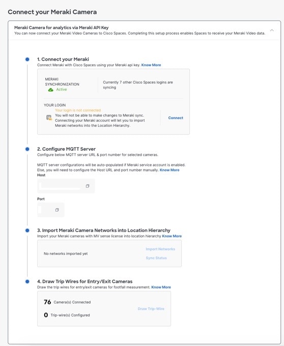
In the expanded widget, click Connect displayed at Step 1.
If already connected to the Cisco Meraki network using the same connection method, the instruction for Step 1 is replaced
with the message indicating that you are connected, and the Connect link is displayed. In such cases, skip this step.
-
For the Meraki Camera for analytics via Meraki Login widget, a window displays with fields to enter e-mail and password for login. Enter the login credentials, and click Submit. After connecting successfully, the content in Step 1 is replaced with the following message: Connected as [e-mail using which you have connected].
-
For the Meraki Camera for analytics via Meraki API Key widget, a window is displayed with an API Key field. Enter the API Key, and click Submit. After connecting successfully, the content in Step 1 gets replaced with the message "Connected with [ masked API key]".
|
|
Step 7
|
Click Import Networks displayed in Step 2 in the Connect your Meraki Camera window.
If the camera network is already imported to the Location Hierarchy section, then skip Step 9 to Step 13.
|
|
Step 8
|
In the Import Networks window, select the Meraki Organization (in which the Meraki Camera Networks are configured) that you want to import.
|
|
Step 9
|
From the Choose Networks area, select the check boxes for the Meraki networks that you want to import.
|
|
Step 10
|
Click Import.
The total number of Meraki networks and cameras that are imported are displayed.
|
|
Step 11
|
Click Finish.
The Meraki Camera configurations in Cisco Meraki will get automatically synchronized with Cisco Spaces. Typically, it gets auto-configured in 48 hours. If there is a delay, manually configure the MQTT server details in Cisco
Meraki as explained in the following step.
|
|
Step 12
|
If want to manually configure the MQTT Server details in Cisco Meraki, perform the following:
The host and port of the MQTT server are account-specific and are displayed in Step 3 within the Cisco Spaces Connect your Meraki Camera window. You must configure these MQTT server details in Cisco Meraki.
-
Log in to the Cisco Meraki dashboard.
-
From the menu in the left pane of the dashboard, choose .
-
In the Name field, click the link for the camera for which you want to configure the MQTT server.
The details of the selected camera are displayed. The Video tab for the camera is displayed by default.
-
Click the Settings tab, and click Sense.
-
To the right of Sense API, click Enabled.
-
Click the Add or Edit MQTT Brokers link.
-
In the Edit MQTT Brokers window, click New MQTT Broker.
-
In the Edit MQTT Broker window that is displayed, enter the following MQTT server details:
-
Click Save.
|
|
Step 13
|
To configure the entry or exit line for the camera, click Draw Trip Wire in Step 4 in the Connect your Meraki Camera window.
|
Note
|
The camera metrics are calculated only at the location level. Ensure that there is a camera at every entrance to a location
where metrics are desired and that the tripwire is drawn for each of those cameras. To ensure accuracy, cameras should be
placed in close proximity to an entrance with a clear view of the entire entry or exit point. Tripwire should be drawn several
feet off the floor at the point of entry or exit. Do not draw a tripwire for any cameras at a location that is not located
at a location-level entry or exit point.
|
|
|
Step 14
|
In the Draw Trip-Wire window that is displayed, click Select Locations, choose the location in which the camera is configured, and click Done.
|
|
Step 15
|
In Select a camera you wish to draw the trip-wire area, select the radio button for the camera for which you want to set the trip wire, and click Next.
|
|
Step 16
|
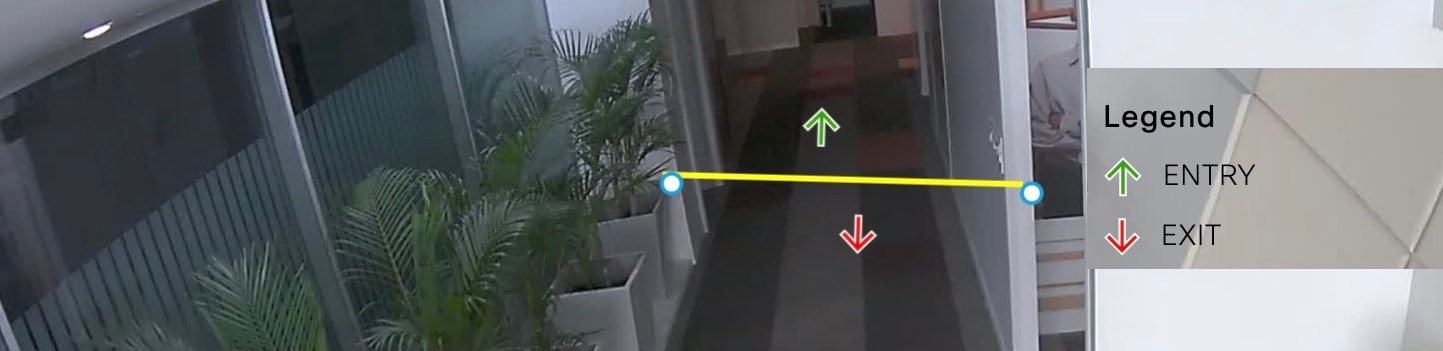
Create the trip-wire by drawing a line on the camera preview image using +.
By default, the entry and exit arrows display in the middle of the tripwire. The green arrow represents the entry and the
red arrow represents the exit. Ensure that the entry and exit arrows are pointing in the direction shown in the following
image. If the arrows are not positioned properly, then click and hold the blue outlined dot at the end of the tripwire line
and drag the mouse to rotate the line and arrow.
|
Note
|
The tripwire functions only if the Cisco Meraki Service account is configured.
|
|
|
Step 17
|
Click both the endpoints of the line to configure the XY coordinates. After clicking the endpoints of the line, the XY coordinates
for the entry and exit arrows are displayed automatically in the Trip-wire status area, and the status gets changed to Set. By default, the status will be Not Set.
|
Note
|
The status will be changed to Set only if you click both endpoints of the line.
|
|
|
Step 18
|
Click Finish.
The camera is configured to use in Cisco Spaces.
|

 Feedback