The documentation set for this product strives to use bias-free language. For the purposes of this documentation set, bias-free is defined as language that does not imply discrimination based on age, disability, gender, racial identity, ethnic identity, sexual orientation, socioeconomic status, and intersectionality. Exceptions may be present in the documentation due to language that is hardcoded in the user interfaces of the product software, language used based on RFP documentation, or language that is used by a referenced third-party product. Learn more about how Cisco is using Inclusive Language.
Location Hierarchy's enhanced user interface simplifies the import of locations in the same structure that you have defined using Cisco AireOS
Wireless Controller, Cisco Catalyst 9800 Series Wireless Controller, or Cisco Meraki, in your wireless network.
The hierarchical structure in maps imported from Cisco Prime Infrastructure or Catalyst Center is automatically reflected in Location Hierarchy.
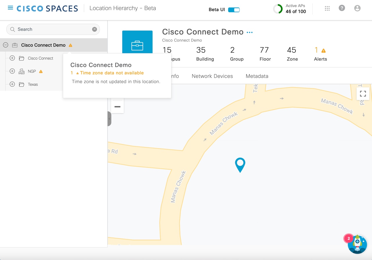
In Location Hierarchy window, the default customer name (root location) is automatically selected, and the Map tab displays the location on the map.
The left pane of the Location Hierarchy window displays the imported root locations with the default customer name (root name). You can click the plus sign to expand
and view the hierarchy. You can view the buildings and the associated floors in the root location.
If you select a root location from the left pane, you can also view additional information related to the number of organizations,
campuses, wireless controller, buildings, groups, floors and zones.
The screen opens with the Location Hierarchy title, a searchable hierarchy tree, a collapsible left pane, and the selected
root location when no other location is already selected.
The selected-location summary can also display a license-level badge when the account is enabled for Smart Licensing and license
information is available for the selected location.
When Smart Licensing is enabled, Cisco Spaces can display license-level badges next to locations in the hierarchy tree. The badge indicates the license level that is applicable
to the corresponding hierarchy node.
For a selected location, building or floor, additional information is displayed in the following tabs:
Map: Displays the selected location on the map
Location Info: Displays the location data information
Network Devices: Displays all the connected network devices and running devices and view the count of these devices
Metadata: Displays the configured metadata information
Rules: Displays the rules for Captive Portal, Engagement, Location Personas and Density
Locations: Displays the location nodes
Users: Displays the users
License Usage: Displays the license type, access points, webex devices, meraki camera, locations and building units information
Note
The Rules tab is displayed only for license levels of Advantage or higher.
The License Usage tab is displayed only when Smart Licensing is enabled for the account.
You can perform the following additional tasks in the Location Hierarchy window:
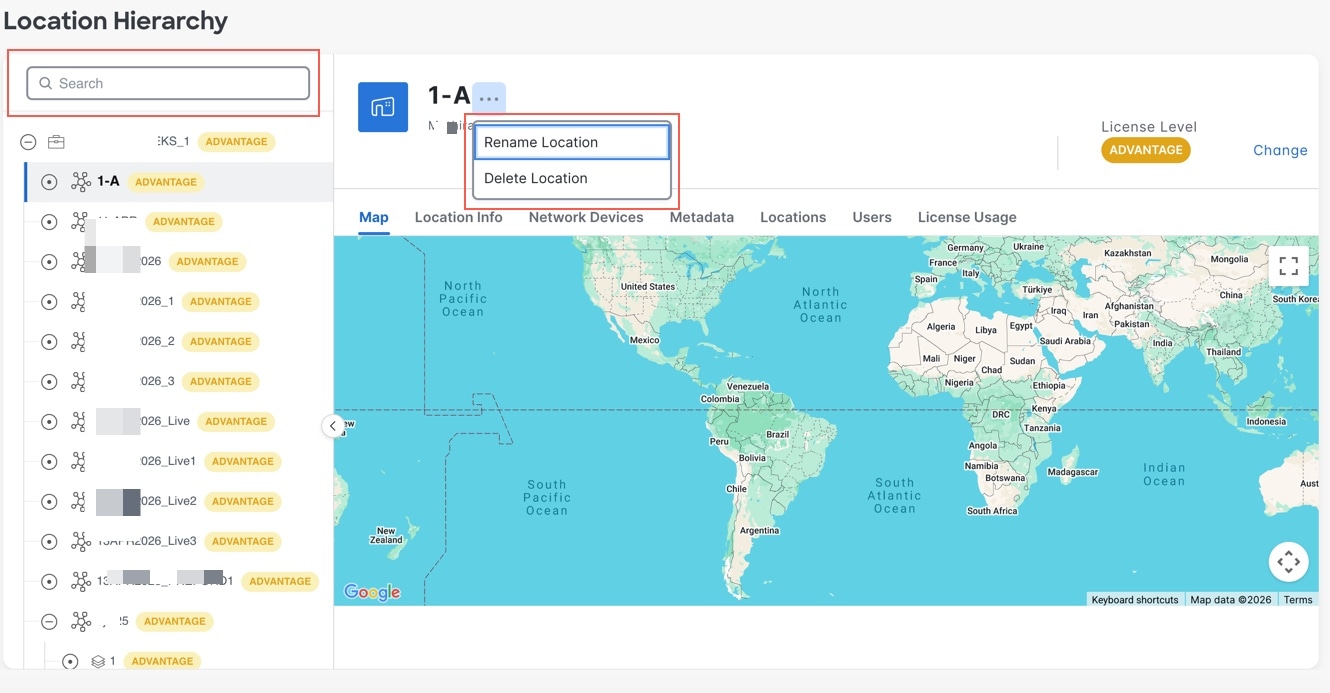
Search: Use the Search field to search for available locations. The search functionality works if you enter just a single character. The Recent Searches area displays the search results.
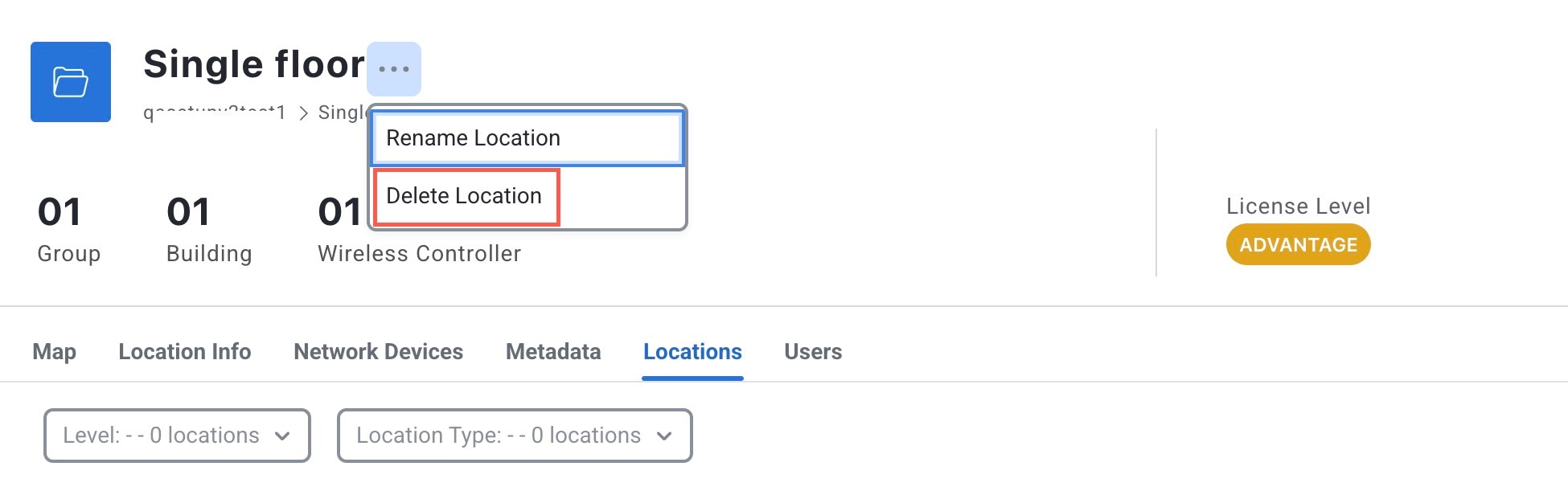
Rename: Click the three dots next to the location and click Rename Location to edit the location name.
For the root location, only the option to rename the location is displayed.
For all other locations except the root, both the options to rename and delete the location is displayed.
Delete: Click the three dots next to the location and click Delete Location to delete the location from Location Hierarchy.
Rename and Delete actions are available only for locations where the signed-in user has Full access. Polygon zones are not renamed from this
menu; they are updated from the floor map. Wireless Controller locations can also show Add/Edit Controller, and AP Zone locations
can show Modify Access Points.
Figure 1. Location Hierarchy - Rename and Delete options
Location Hierarchy shows rich maps, if they are available for a particular floor. The option to upload rich maps is currently available under
Setup > Locations & Maps. Click the 3D toggle button to switch between 2D and 3D floor maps.
The 2D/3D toggle is shown only for floor locations. The 3D view is enabled when the selected floor has supported rich-map
data and the parent building or network has a valid rich-map status. If rich maps are not enabled, the 2D/3D control is displayed
in a disabled state.
In Location Hierarchy, only those locations that a Cisco Spaces user can access are displayed. The accessibility to these locations are defined
when you create or edit roles or invite or edit the Cisco Spaces user in Admin Management.
Manage Locations in Map view
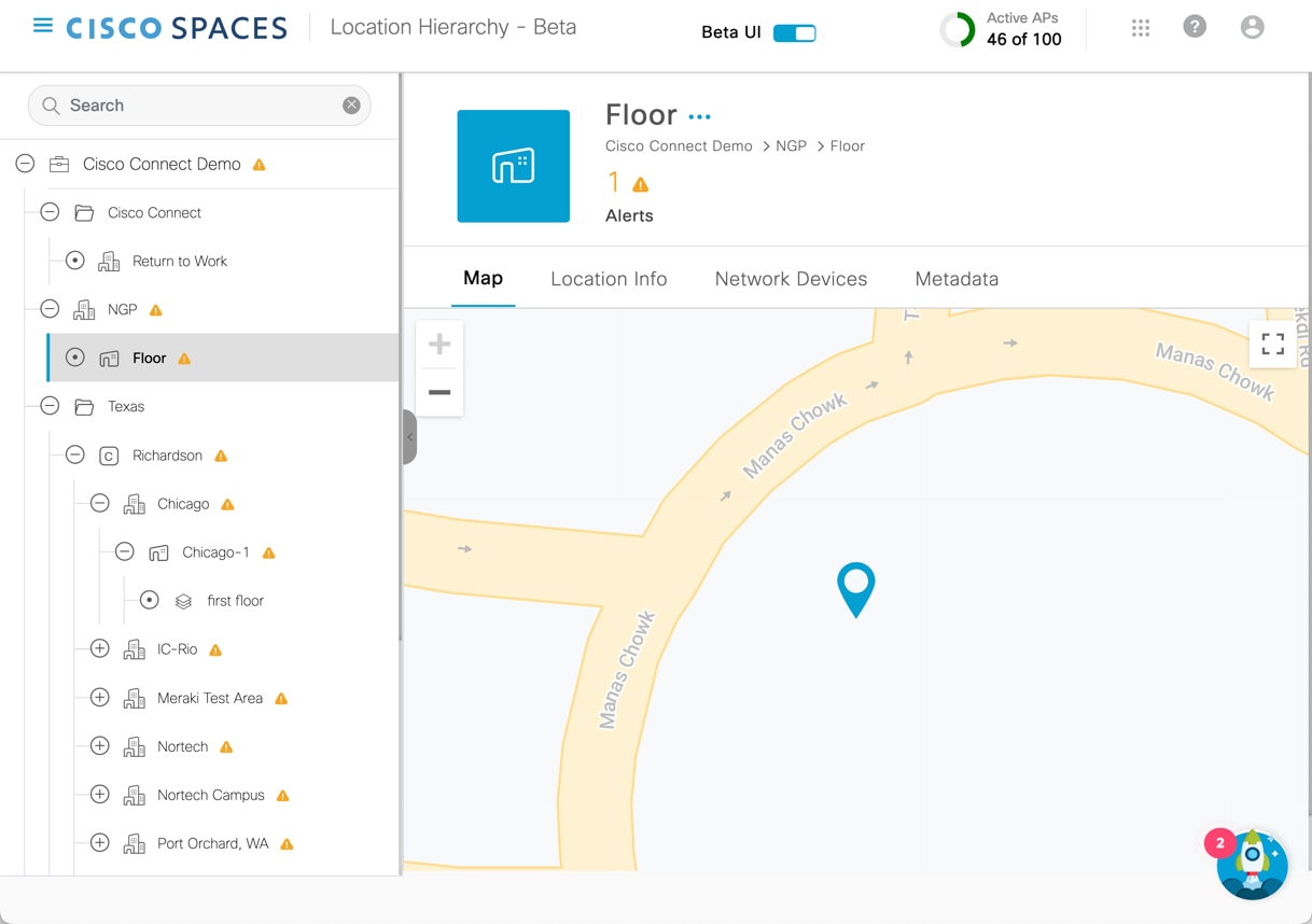
Use the Map tab (Cisco Spacesdashboard > Menu icon () > Location Hierarchy > Root Location) to view the selected location, campus, building and floor information on the map.
The Map tab displays diff ernet map types such as default world map, latitude and longitude based maps, and 2D or 3D floor maps.
If you select the root location, the default world map is displayed.
However, in some instances, the map automatically zooms into the precise location on the map and is displayed with a map pin.
You can click on the map pin to view the additional information such as location address, total area, maximum capacity, time
zone details and so on. The precise location is plotted based on the latitude and longitude information.
Figure 2. Map Tab
If you select a building, the default world map is displayed.
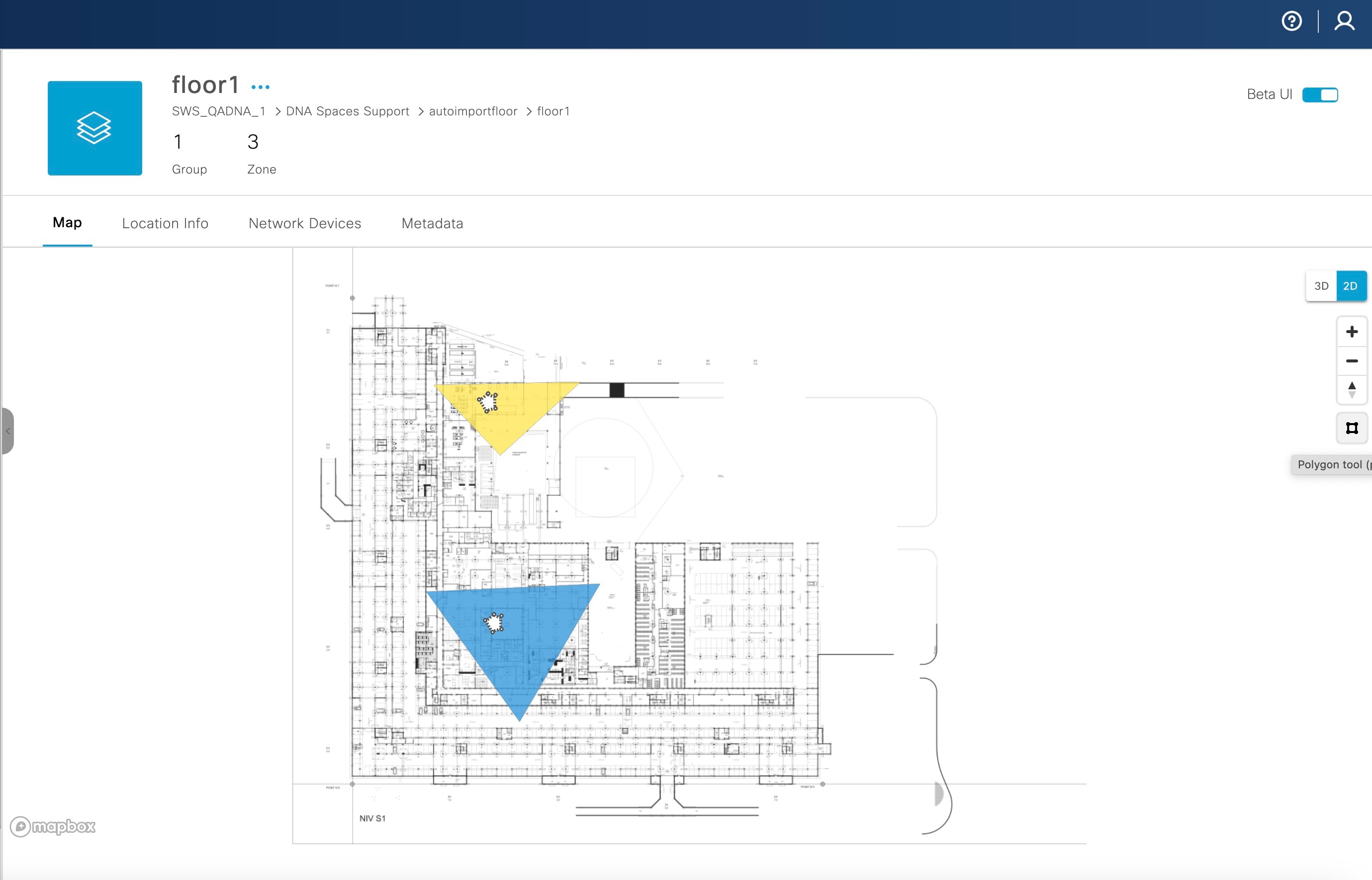
If you select a floor, the exact floor map image is displayed. Use the Polygon tool () to create zones. For more information, refer to Create a Zone for a Floor Location.
Depending on the location you select, view these information:
Organization
Campus
Building
Floor
Zone
Create a Zone for a Floor Location
Use the Map tab to create Cisco CMX zones in Location Hierarchy.
The current implementation creates and updates polygon zones from the floor map for supported floor maps. Zone creation is
available only when the selected floor has Full access and a 2D floor map is available.
Note
Currently, Cisco Meraki zone-based reports are only supported in the Live Occupancy application and Firehose device location update events.
In Location Hierarchy 2.0, you can create polygon zones for the floor locations under the Cisco Meraki network. To create
polygon zones on the floor map, use the Polygon tool () that is available in the floor map view under the Map tab. The new polygon zones created are displayed under both Location Hierarchy and Location Hierarchy 2.0.
Procedure
Step 1
Log in to Cisco Spaces.
Step 2
In the Cisco Spaces dashboard, click the Menu icon () and choose Location Hierarchy.
The Location Hierarchy window is displayed.
Step 3
In the left pane, navigate to the required floor location.
The floor map is displayed.
Figure 3. Map Tab
Step 4
Click the Polygon tool () on the map.
The cursor changes to a plus icon.
Step 5
Click the required map area and move the cursor to draw a polygonal zone of your choice.
Step 6
Double-click to complete the zone creation.
A pop-up window is displayed on the right pane.
Step 7
In the Zone Name field, enter the new zone name.
Step 8
Select the overlay color to distinguish the zone.
Step 9
Click Save.
The new zone is created, and the Location Hierarchy window is refreshed to display the root location.
In the left pane, navigate to the floor where you created the new zone and the zone is now listed as a new item under the
floor hierarchy.
Step 10
(Optional) Click the Polygon tool () on the map to update the zone details.
Update Location Information
Use the Location Info tab (Cisco Spacesdashboard > Menu icon () > Location Hierarchy > Root Location) to view and edit the location information.
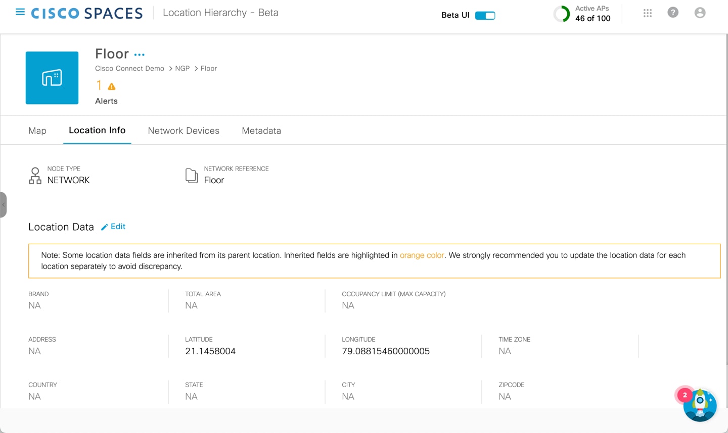
For the selected location, the Node Type and Network Reference details are displayed.
The Location Info tab displays read-only details for the selected location. The displayed details can include Node Type, Network Reference, Brand, Total Area, Occupancy Limit, Address, Country, State, City, Zipcode, Latitude, Longitude, and Time Zone.
The Node Type value identifies the hierarchy level of the selected location, such as ROOT, NETWORK, or FLOOR. The Network Reference value identifies the reference name associated with the selected location in the hierarchy.
If a value is not configured for the selected location, Cisco Spaces displays NA.
Figure 4. Location Info Tab
Click Edit to update location information. For more information, refer to Edit Location Info.
Note
Location data fields inherited from the parent location are highlighted in orange. For example, a floor can inherit Address and Time Zone values from the parent network or building. Update each location separately if you want to override inherited values.
Edit Location Info
Procedure
Step 1
Log in to Cisco Spaces.
Step 2
In the Cisco Spaces dashboard, click the Menu icon () and choose Location Hierarchy.
The Location Hierarchy window is displayed.
Step 3
In the left pane, navigate to the required location.
Step 4
Click the Location Info tab.
Step 5
Click Edit next to Location Data.
The slide-in window is displayed.
Step 6
Update the following location information as required:
Note
The fields displayed in the Edit Details drawer vary based on the selected node type. For the root location, the drawer displays fields such as Location Name, Brand, Total Area, Unit, Occupancy Limit, and Time Zone. For network or building locations, the drawer can also display Address, Latitude, Longitude, and the map panel.
Location Name: Edit the name of the location.
Brand: Edit the name of the brand.
Total Area: Edit the total area details. The value must be numeric and cannot include commas.
Unit: Select the unit for the total area entered. The options are Square Feet and Square Meter.
Occupancy Limit (Max Capacity): Enter a positive integer.
Address: Enter the address details and select from the displayed options. The selected address is plotted on the map displayed on
the right side. The map panel provides Map and Satellite views and supports marker-based location selection.
Latitude and Longitude: Edit decimal coordinates directly or drag the marker on the map. Values can be positive or negative decimal numbers and
cannot include commas.
Time Zone: Select a valid time zone from the searchable Time Zone list.
Step 7
Click Save.
Edit Access Point Prefix
You can add APs of multiple prefixes to a network. For example, if you have APs with prefixes, AB, BC, and CA, and if you
want to group the APs with AB and BC under one wireless network, you can do so.
The Access Points Prefix Used option will be available in the Location Info tab only for the network locations. However, the Access Points Prefix Used option will not be available for the Unconfigured network.
To add APs of multiple prefixes to a network of a Cisco Wireless Controller or Cisco Catalyst 9800 Series Wireless Controller,
follow these steps:
Procedure
Step 1
Log in to Cisco Spaces.
Step 2
In the Cisco Spaces dashboard, click the Menu icon () and choose Location Hierarchy.
The Location Hierarchy window is displayed.
Step 3
In the left pane, navigate to the required network.
Step 4
Click the Location Info tab.
Step 5
Click Add/Edit next to Access Point Prefix Used.
Step 6
In the Add/Edit Prefix window, in the Prefix field, enter the prefix.
The access points with the prefix entered get listed.
Step 7
Click Add Prefix.
The newly added prefix gets listed under Added Prefixes in the right pane of the window. Add Prefix is enabled only if the APs with prefix entered are available.
Step 8
Click Save.
After adding the prefix, the APs under the unconfigured network with this prefix is moved to this network.
Use the trash icon in the Existing Prefixes panel to remove a prefix before clicking Save.
View the Network Devices
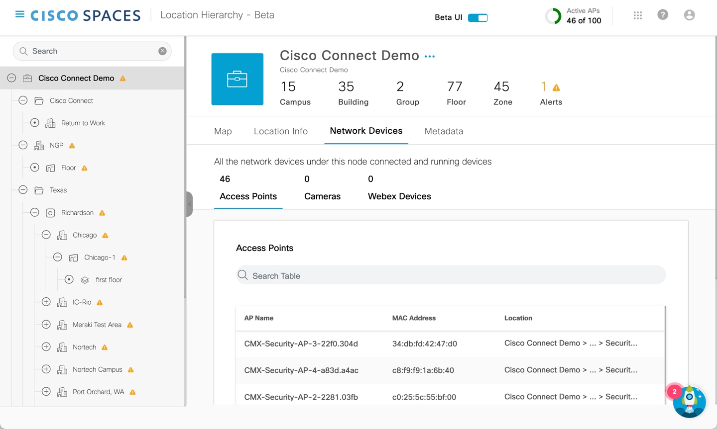
Use the Network Devices tab (Cisco Spacesdashboard > Menu icon () > Location Hierarchy > Root Location) to view all the network devices under the selected node. The root location displays all the connected devices available
within the location hierarchy.
Figure 5. Network Devices tab
Depending on the selected location, you can view the following information:
Access Points: Displays the name of the AP, MAC address and the location hierarchy path. Use the Search Table field to search for a specific AP. Click the copy icon next to the Location field to copy the hierarchy path. Navigate to the Setup window to configure the AP.
Cameras: Displays the connected camera details such as camera name, serial number, MAC address and status of the trip-wire as a set
or not. Use the Search Table field to search for a specific camera. Navigate to the Connect your Meraki Camera window to connect additional devices.
Security Appliances: Displays the detailed list of security appliance devices for the respective locations.
Webex Devices: Displays the connected Cisco Webex devices.
Linked Devices: Displays the linked devices configured for this location. You can link IoT Devices, Non-Webex Signages and Smart PUDs.
Switches: Displays the switches configured for this location. Navigate to Setup > Wired Network to onboard your switches.
Configure Metadata
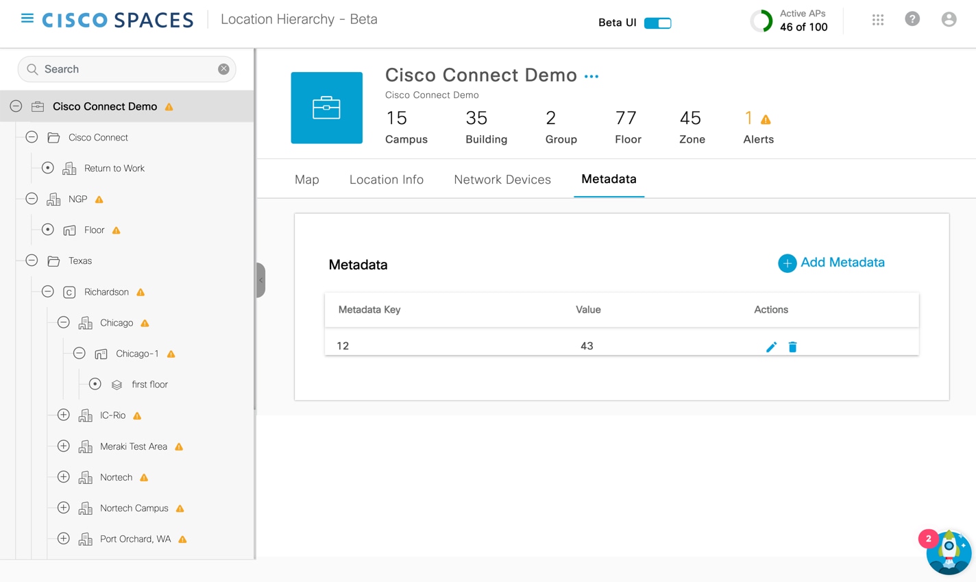
Use the Metadata tab (Cisco Spacesdashboard > Menu icon () > Location Hierarchy > Root Location) to view the metadata information. If metadata is not configured yet, click Add Metadata to add metadata. For more information, refer to Add Metadata.
Figure 6. Metadata Tab
Depending on the selected location, you can view the following information:
Metadata Key: Displays the metadata key.
Value: Displays the value for the metadata key. The value can be alphanumeric and accepts special characters also, for example,
xyz123@.
Add Metadata
Procedure
Step 1
Log in to Cisco Spaces.
Step 2
In the Cisco Spaces dashboard, click the Menu icon () and choose Location Hierarchy.
The Location Hierarchy window is displayed.
Step 3
In the left pane, navigate to the required location.
Step 4
Click the Metadata tab.
Step 5
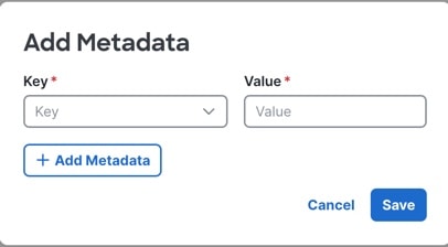
Click Add Metadata.
Figure 7. Add Metadata
Step 6
In the Key field, enter or select a metadata key.
Step 7
In the Value field, enter a value for the key.
Step 8
(Optional) Click Add Metadata to add multiple metadata keys and the corresponding values.
Click the Delete icon next to the metadata key to delete the keys.
Step 9
Click Save.
After Save, the Metadata tab refreshes and displays the saved keys and values. Existing metadata can be edited or deleted from the Actions
column.
View Locations
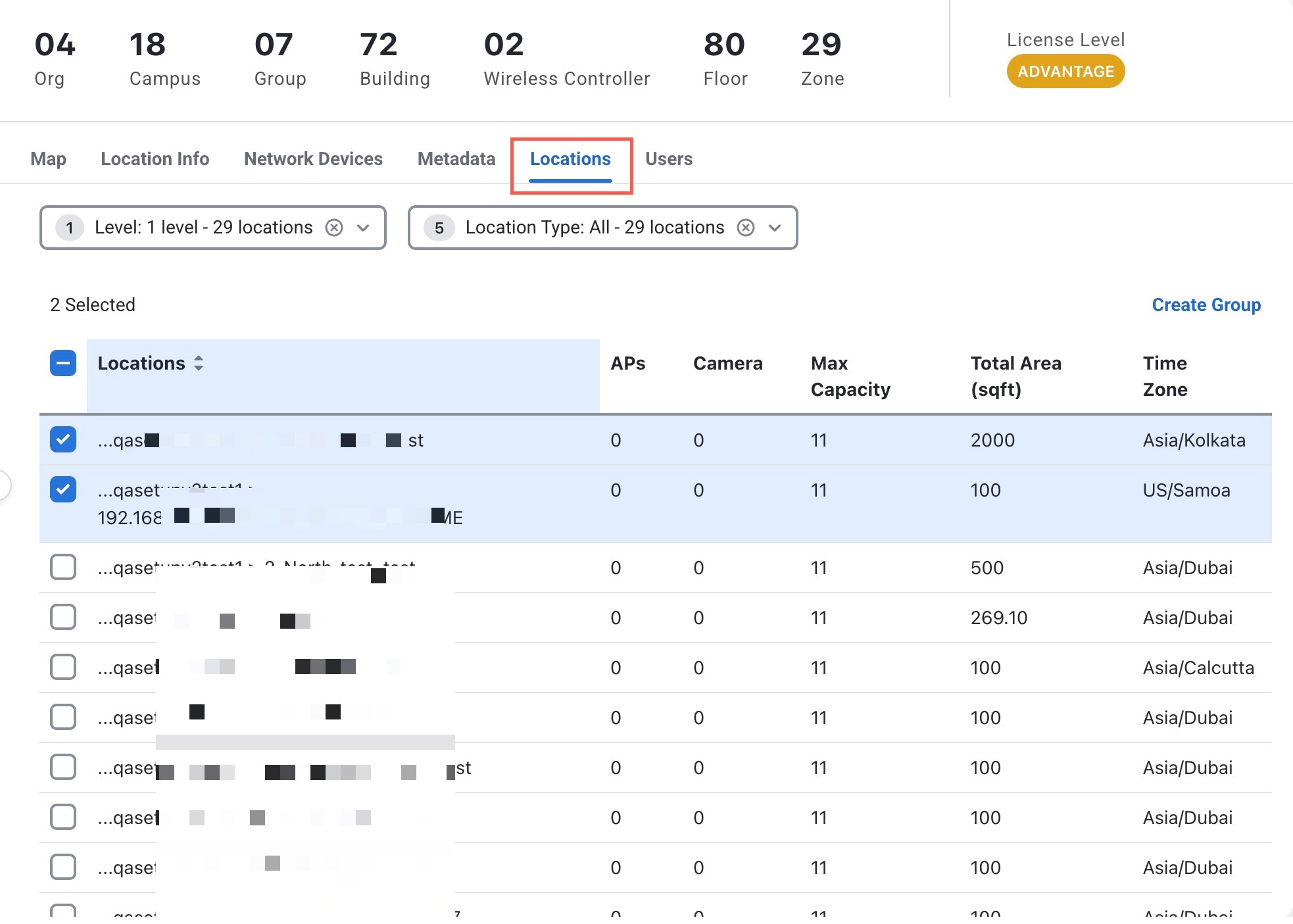
Use the Locations tab (Cisco SpacesDashboard > Menu icon () > Location Hierarchy > Root Location) to view the location information such as Location Type and Level.
Use the Location Type and Level drop-down options to select the location preferences. The location types are:
Network/Building
Campus
Group
Organization
Wireless Controller
CMX
View these details for the selected location:
Locations
APs
Camera
Max Capacity
Total Area (sqft)
Time Zone
Select the required check box next to the location and click Create Group to add location to create your own group.
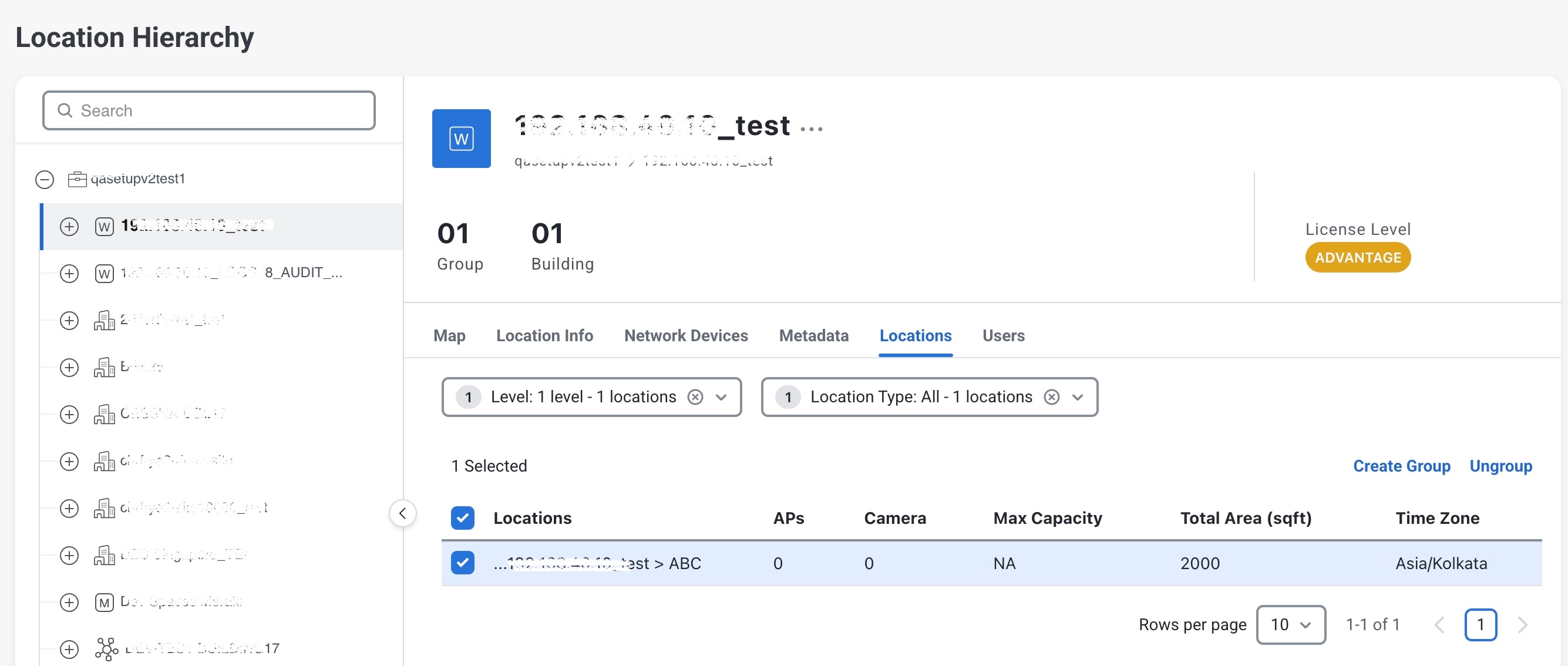
If a single selected row is a group that has child locations, the Locations tab also displays Ungroup.
Create a Group
Use this procedure to organize multiple child locations by creating a group.
Before you begin
Verify that the parent building and the child location that you want to group already exist.
Verify that your account has permission to update the location hierarchy.
All selected locations must have the same parent node. If the selected locations belong to different parents, Cisco Spaces
displays an error and does not create the group.
Procedure
Step 1
In the left navigation pane, click Location Hierarchy.
Step 2
In the left pane, navigate to the location where you want to create a group.
Step 3
Click the Locations tab.
Step 4
Check the check box for each location that you want to add to the group.
Figure 8. Locations Tab
Step 5
Click Create Group.
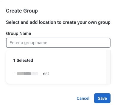
The Create Group pop-up window is displayed.
Step 6
In the Create Group pop-up window, enter a name in the Group Name field.
Figure 9. Create Group
Step 7
Review the selected locations, and then click Save.
Step 8
Verify that the new group appears in the hierarchy under the selected building.
The new group is created under the selected building and moves the selected locations under that group. The building summary
also updates to show the new group count.
Step 9
(Optional) Perform these steps if required.
To ungroup the location, select a group row that has child locations and click Ungroup.
Figure 10. Ungroup
In the warning dialog, click Yes to confirm the ungroup action.
To delete a group or another non-root location, open the location action menu and click Delete Location.
Figure 11. Delete Location
Split License
Split License feature allows you to upgrade licenses at the location level.
You can upgrade location-level license to higher tiers (ADVANTAGE or Unlimited), regardless of the account-level license being
at a lower tier, for example: ESSENTIAL, EXTEND, SMART OPS, and SMART VENUES. This flexibility extends to the floor level
within the Location Hierarchy. Use the License Level Change option available in the Location Hierarchy (Beta UI) to upgrade the license type.
IoT Services licenses can be assigned at the campus or building level. The effective license level is displayed for supported
locations in the hierarchy.
A valid IoT Services license is required to configure IoT Services for a campus or building. If the selected location does
not have the required license, users can view the location and its existing information but cannot modify the IoT Services
configuration.
To enable additional IoT Services capabilities for a location, assign a supported higher-tier license to the campus or building
by using the location-level license change workflow.
The apps that include Split License support are:
Location Analytics
Live Occupancy
Captive Portal
Detect and Locate
IoT Explorer
Environmental Analytics
Engagements
Location Personas
Space Manager
Space Experience
To activate Split License feature for a location, click Change and select the license upgrade options.
The Change link is displayed next to License Level in the selected-location header. Use this link to modify the license level for the selected location.
Note
This upgrade allows you to experience higher-tier license features in Location Analytics app and also in the Density Rule feature in Live Occupancy application.
The Split License feature is only available for accounts registered with the Cisco Smart Software Manager (CSSM) system and integrated with Cisco Spaces account by registering the Smart Licensing token with the Cisco Spaces dashboard. If your account is not registered with CSSM, we recommend reaching out to your account administrator.
View Users
Use the Users tab (Cisco SpacesDashboard > Menu icon () > Location Hierarchy > Root Location) to view the users and their role permissions.
View these details:
User
Role
Permissions: Read & Write
Permissions: Read only
Locations
Use the Search option to search for users. You can click a user to edit the permission setting in the Admin Management > Edit User window.
View License Usage
Use the License Usage tab (Cisco SpacesDashboard > Menu icon () > Location Hierarchy > Root Location) to view the license type applicable for the logged in account.
The License Usage tab is visible only when Smart Licensing is enabled. For a selected location, usage is loaded from the location-specific
license service.
View these details:
License
Access Points
Webex Devices
Meraki Camera
Locations
Building Units
Locations indicates the number of location nodes counted for license usage under the selected hierarchy context. Building
Units indicates the number of building-level units counted for license usage under the selected hierarchy context.
 ) > Location Hierarchy > Root Location) to view the selected location, campus, building and floor information on the map.
 ) to create zones. For more information, refer to Create a Zone for a Floor Location.

 Feedback