Set Up Locations and Maps

Locations and Maps

The Locations and Maps feature in Cisco Spaces helps to import, normalize and unify network hierarchies from various sources such as Cisco Meraki, Catalyst Center, and Cisco Prime Infrastructure into a single business-orientated hierarchy. Use this feature as a platform to standardize the network hierarchy structure and provide a standardized location hierarchy view.

Apart from the traditional way of creating location hierarchy by importing/syncing from network sources, this new feature includes a new option to create a business centric hierarchy from a Microsoft Excel (.xlsx) file. The Microsoft Excel (.xlsx) file import allows to perform bulk add/update of the metadata information for multiple locations.

While Cisco Spaces creates a logical location hierarchy matching the network hierarchy, most Cisco Spaces users have one more source where the hierarchy/names differ because of the taxonomy, or because they are managed by different teams/people. With the Locations and Maps feature, you can create a business orientated hierarchy, merge/unify hierarchies from different network sources into the business hierarchy making it a clean unified hierarchy thereby helping in managing various outcomes.

You can import your business locations and organize them within Cisco Spaces based on the physical business locations and network deployments. You can also organize the hierarchy based on specific brands, regions, campuses, and other taxonomies relevant for the business.

The Locations and Maps feature in Cisco Spaces helps to translate your IT network view into a business view and present a cleaner business relevant insights report. Any changes to your network topology are automatically reflected in Cisco Spaces making it easy to manage.

The Locations and Maps window has these tabs:

  • Locations: Use this tab to add or manage locations.

  • Network Maps: Use this tab to add Network Maps.

  • Digital Maps: Use this tab to add or manage Digital Maps.

Use the Filter option in these tabs to open the Filter drawer, select your filter values, and then apply them to the list.

Each tab under Setup > Locations and Maps includes a list-level search field and a Filter drawer. You can open the Filter drawer, select one or more filter values, click Apply, and remove individual filters by clicking the active filter chips above the table or reset the list by clicking Clear all.

You can also narrow the list by selecting a location from the location hierarchy picker within the Filter drawer. This allows you to filter by campus, building, floor, network, or other supported hierarchy levels before applying filters specific to each tab.
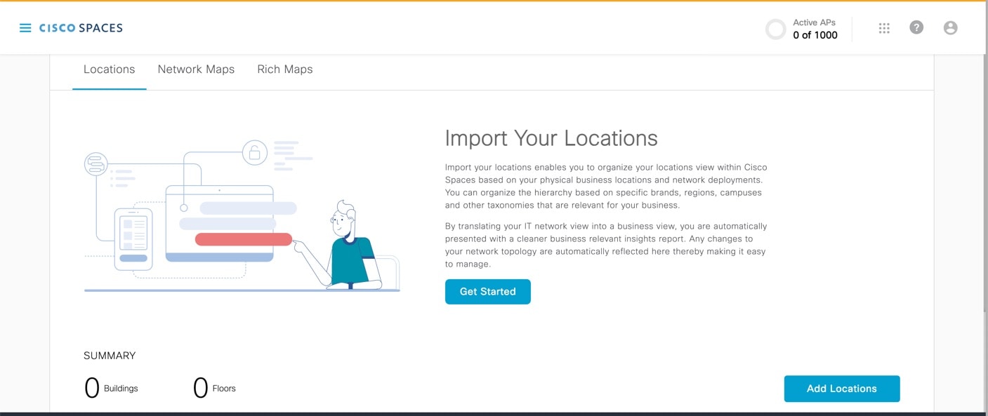
Figure 1. Locations and Maps

Locations Tab

The Summary section in the Locations tab displays the number of buildings and floors. The Buildings section in the Locations tab displays the following information related to the imported location:

  • Name

  • Path

  • #of Floors

  • Source

  • Essential Location Info

Perform these tasks:

  • Enter the building name in the Search Locations field and filter the specified building information.

  • Click Export to export the location data. You can click Download to download the same.

  • Click Recent Activity to open the Recent Activity window and view the recent activity details.

  • Click Import Locations to import locations. For detailed information, see Import Locations.

When no locations are available, the Locations tab shows a Day 0 onboarding view with a Click to Get Started call to action (CTA). To start importing locations, navigate to Setup > Locations and Maps > Locations, then click either Click to Get Started or Add Locations.

To filter the Locations list, go to Setup > Locations and Maps > Locations and select Filter. In the Filter drawer, you can choose a hierarchy node, one or more Sources, a Number of Floors value or a custom floor range, and Location Metadata status. Click Apply to refresh the list.

After applying filters, the active filter options appear above the table. You can remove filters one at a time by clicking the individual filter options or reset the list to show all locations by clicking Clear all.

If imported locations require review, a review banner displays the number of pending items. Click Review on the banner to open the review workflow, where you can complete actions such as merge, retain, create, skip, or delete as needed.

If essential location information is incomplete, you can update it from the warning message or the row action menu. Navigate to the relevant building in the Locations table, click the warning icon or the action menu, and select the metadata update option to complete the missing details.

Network Maps Tab

The Network Maps tab also displays the imported location information. The Buildings section in the Network Maps tab displays the following information related to the imported location:

  • Name

  • Path

  • #of Floors

  • #of APs

  • Source

  • Network Map Status

Perform these tasks:

  • Enter the building name in the Search Locations field and filter the specified building information.

  • Click Recent Activity to open the Recent Activity window and view the recent activity details.

  • Click Add Network Map to add network maps. For detailed information, see, Add Network Map.

In the Network Maps tab, you can review two summary indicators before uploading or validating maps: the number of buildings with network maps and the number of network maps that are geolocated. These indicators help you confirm how many locations already have map coverage and how many are positioned geographically.

To filter network map results, navigate to Setup > Locations and Maps > Network Maps, then select Filter. In the Filter drawer, choose a hierarchy node, one or more Sources, a Number of APs value or custom AP range, and a Number of Floors value or custom floor range. Click Apply to refresh the list.

If a building does not yet have a network map, a warning tooltip appears in the building row. Open the tooltip and use the provided action to start the upload or import flow for that building.

Digital Maps Tab

Digital Maps is an upgraded version of Rich Maps. Two variations of Digital Maps available are:

  • STANDARD Maps: Shows 2D flat maps without support for meeting rooms or integration with Cisco Smart Workspaces.

  • PRO Maps: Shows 3D visualizations and include all the available features of Cisco Smart Workspaces, similar to Rich Maps.

The Digital Maps tab also displays the imported location information.

The Buildings section in the Digital Maps tab displays the following information related to the imported location:

  • Name

  • Path

  • #of Floors

  • Digital map status

  • Actions


    Note


    In the Digital Maps tab, the Actions menu adapts to the building’s status. These options are available based on the building state.

    • Add digital maps

    • Add/update floors

    • Set default map view

    • Set address

    • Confirm address

    • Review

    • Cancel

    • View/Edit

    • Preview

    • Delete Digital Map

    • View History

    • Export to Catalyst Center


Perform these tasks:

  • Enter the building name in the Search Locations field and filter the specified building information.

  • Click Recent Activity to open the Recent Activity window and view the recent activity details.

  • Click Add Digital Map in the Actions column to add digital maps. For detailed information, see Add Digital Map.

  • You can also click Upload CAD File under Actions column to add digital maps to the selected location.

To filter digital map results, navigate to Setup > Locations and Maps > Digital Maps, then select Filter. In the Filter drawer, choose a hierarchy node, one or more Processing Status values, and a Number of Floors value or custom floor range. Click Apply to refresh the list.

After you apply filters, the selected values appear as filter chips above the table. You can remove a single filter from the chip row or click Clear all to reset the filtered list.


Note


Locations with ACT/UNLIMITED licenses have exclusive access to the PRO variant, while the STANDARD variant remains accessible to other license types, including SEE, EXTEND, and SMART_OPERATIONS.


Digital Maps: User Experience Enhancements

The following enhancements are made in the Cisco Spaces dashboard:

  • The Select Floor window is redesigned to minimize user effort. The new design reduces the number of entries required from users, enabling a quicker and more efficient process by automatically generating the floor level number and short name for each floor.

  • The file upload process is enhanced to improve efficiency. You can now upload files for multiple floors simultaneously, with each being processed in parallel. The full-page loader that previously displayed during single floor uploads is replaced by individual loader indicators for each floor, allowing clear visibility into the status of each upload.

    If any floor file requires additional time, you have the option to cancel that specific upload without affecting the progress of others. This enables better management of successful uploads and more effective time allocation.

  • Map Processing Status Reporting with Estimated Time and Email Notifications: Map Processing feature is enhanced to address the issues reported with time-intensive map generation. With this enhancement, after you successfully submit the map, the window is displayed with an estimated processing time. You can also view the processing status, including a tentative ETA or error details, by hovering over the status message for each building in the Digital Maps list view. Additionally, the submitter receives email notifications regarding any changes in the map status.

  • Re-Processing Maps/Re-submission of CAD Files: The map re-processing experience is enhanced to include a feature that allows you to specify the exact changes needed. This helps to reduce the turnaround time. You can select from a list of common reasons and provide additional comments, along with any supporting documents or images as evidence for the re-processing request.

The current processing status experience enhances user interaction by providing richer hover details. When you hover over the processing status, the interface shows floor-level grouping, the submitted date, the expected review timeline, the draft state, and detailed error information for the affected floors.

If a preview session is interrupted, you can resume your previous work or discard unpublished changes. This feature helps you return to unfinished map preparation without restarting the entire workflow.

When you try to save or publish with unsaved editor changes, the interface displays confirmation dialogs. These dialogs let you choose to save and continue or discard the pending edits based on your selected action.

Network Map Calibration

The Network Map Calibration tool enables precise alignment of 2D network map images with 3D Digital Maps. You can access the tool from the Digital Map Editor, allowing you to precisely place GPS markers ensuring client and access point positions are accurately represented.

The Network Map Calibration link is enabled in the user interface only for maps that have associated network maps.

Use Network Map Calibration after you have a digital map preview and a related network map for the same building. Open the Digital Maps editor for that building, launch the calibration tool, and align the network map markers so that device and AP positions match the final map view more accurately. This process helps ensure better accuracy between the network map and the digital map.

STANDARD Maps (BETA)

STANDARD Maps (BETA): The beta version of STANDARD Digital Maps (with a beta watermark) has been introduced in Cisco Spaces. The STANDARD maps are generated more quickly compared to the PRO version but with fewer features, thus supporting a limited range of use cases.

You might notice that the orientation and positioning of STANDARD maps may not always align perfectly with the actual building position on the earth map. We recommend that you adjust the position and orientation of STANDARD maps using the tools available in the Standard Map preview.


Note


  • The PRO maps are exclusively available to locations with ACT or UNLIMITED licenses, while STANDARD maps are accessible for locations with SEE or Extend licenses.

  • You can use the STANDARD version of the map for device placement. For locations with ACT or UNLIMITED licenses, use the STANDARD map until the PRO version is fully generated.


Import Locations

Use the Locations tab to import the business hierarchy.

After you successfully import locations, you can immediately review the imported hierarchy and update any incomplete metadata. Then, use the Filters option in the Locations tab to validate the imported data by source, floor count, or metadata completeness before proceeding to Digital Maps. This process helps ensure your data is accurate and complete before moving forward.

Procedure


Step 1

Log in to Cisco Spaces.

Step 2

In the Cisco Spaces dashboard, click the Menu icon () and choose Setup > Locations and Maps.

The Locations and Maps window is displayed with the Locations tab selected. The other tabs available are Network Maps and Digital Maps.

Step 3

In the Locations tab, click Add Locations. If locations are already imported and available, then Import Locations option is displayed.

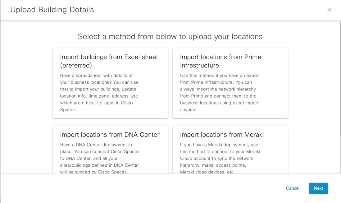
The Upload Building Details window is displayed with the various methods to upload the locations.

Figure 2. Upload Building Details

Step 4

Import the locations using the following methods:

The imported location details are displayed in the Locations tab.

  • The Summary section displays the details of the buildings, floors, missing location metadata information and locations that need review.

  • The Building section in the Locations tab displays the location details such as name, path, number of floors, source and so on.

  • In the Building section, the Essential Location Info field displays an alert if the required location metadata is not updated.

Step 5

In the Essential Location Info field, click Alert icon () to add the missing metadata if required.
A pop-up window is displayed with the information related to missing location metadata. Click Click Here to update the location info.

Step 6

Click Review to view and proceed with location reviews. For more information, see Review Locations.

The Review option is displayed when you import locations using methods other than Import buildings from Excel sheet method.

Step 7

(Optional) In the Locations tab, use the following options as required:

  • Export: Click to export the imported business location details into a Microsoft Excel file (.xls). You can click Download to download the same.

  • Recent Activity: Click to view the recent activity details. The Recent Activity slide in window displays the history of activities happened in the recent past.

    • File Name

    • User

    • Type

    • Time

    • Status

  • Filter: Click to view the filter options. In the Filter slide-in window that is displayed, choose the location from the Locations drop-down list and the required filter options and click Apply. The filter options are: Source, # of Floors and Location Metadata.


Import Buildings from Microsoft Excel Sheet

Use the Import buildings from Excel sheet option to add locations by importing a Microsoft Excel (.xlsx) file. We recommend that you choose this method to import the locations with buildings, location metadata, time zone, address, and so on that are important for Cisco Spaces application.

Procedure


Step 1

Log in to Cisco Spaces.

Step 2

In the Cisco Spaces dashboard, click the Menu icon () and choose Setup > Locations and Maps.

The Locations and Maps window is displayed with the Locations tab selected.

Step 3

In the Locations tab, click Add Locations. If locations are already imported and available, then Import Locations option is displayed.

The Upload Building Details window is displayed with various methods to upload the locations.

Step 4

Click Import buildings from Excel sheet and click Next.

Step 5

In the Import Location Details window, drag and drop the Microsoft Excel (.xlsx) file or click Click here to upload to upload the Microsoft Excel (.xlsx) file with details of the business locations to be imported.

Note


If you do not have the template, you can download the template from the link available in the Import Location Details window and upload the same with the building details in the correct format.

Step 6

Click Next.

The Import Location Details window is displayed with location information from the Microsoft Excel (.xlsx) file in the left column and existing location level and group level information in the right column.

Step 7

In the Import Location Details window, map the imported location metadata in the Column from CSV column with the corresponding hierarchy and group levels under the Link to drop-down and assign respective location metadata values accordingly.

The options available in the Link to drop-down are:

  • Location Info: Use this for location metadata information such as Country, City, Occupancy, Band, Address, Time Zone and so on. You must assign a corresponding metadata value also.

  • Hierarchy Level: Use this to map the Level column value from the Microsoft Excel (.xlsx) file. The Microsoft Excel (.xlsx) file can have multiple Level values. Level values from the Microsoft Excel (.xlsx) file are mapped as Hierarchy Level in the Location Hierarchy.

    For each Hierarchy Level, you can assign a grouping level value. The options are: Grouping Level1, Grouping Level2 and Grouping Level3.

    In the Microsoft Excel (.xlsx) file, you can have NYC1 Campus as Level1 and NYC2 Campus as Level2. In the Import Location Details window, you can map Level1 and Level2 with Hierarchy Level in the Link to drop-down list. For Level1, you can assign the grouping value as Grouping Level1 and Grouping Level2 for Level2.

  • Location Name: Use this to map with the Location column value from the Microsoft Excel (.xlsx) file.

    Note


    You need not assign any value for Location Name. The location name is directly fetched from the Excel file and cannot be modified or mapped with any header columns.

  • Location ID: The Location ID is auto-generated after the location import is successfully complete.

Step 8

Click Next.

The Merge Locations window is displayed.

  • A message indicating that the Location Hierarchy in Cisco Spaces is updated to include new locations discovered by importing the Microsoft Excel (.xlsx) file.

  • The Merge Locations window displays the number of new locations and their levels imported using Import buildings from Excel sheet method.

  • The Merge Locations window displays three columns: Locations found in CSV, Actions and Existing Locations.

  • You must review the hierarchy and take necessary action using the Action drop-down list.

  • You can use the Search Location field to enter search criteria and search for location name.

Step 9

In the Locations found in CSV, click the plus symbol to expand the location.

Step 10

From the Actions drop-down list, select the required action to merge the imported location with the existing Location Hierarchy displayed on the right side.

The options are:

  • Create New: Select this option if you want to create the imported location as a new location into the existing Location Hierarchy.

  • Merge With: Select this option if the imported locations from the Microsoft Excel (.xlsx) file are repeating and
 the location already exists in the Location Hierarchy. We recommend that you perform this action with attention as you cannot revert once you merge the locations.

  • Skip: Select this option if you want to skip importing the 
locations into the Location Hierarchy. We recommend that you perform this action with attention as you cannot revert once you skip the locations.

Note


In the existing Location Hierarchy:

  • If there are no existing campuses or buildings, the new imported locations are added as new entries.

  • If there are locations with similar name, you can merge the new locations with the existing ones.

Step 11

Click Next.

You need to review the merge location updates displayed in the Merge Locations section. You can view the number of locations that are processed.

Step 12

Click Submit.

A success message is displayed indicating that the location details are uploaded.

You can click Add Digital Maps if you want to add digital maps or View Locations to view the locations.

Step 13

Click Close this window to return back to Locations tab.

The Building section in the Locations tab displays the location details such as name, path, number of floors, source and so on. The Summary section displays the details of the buildings, floors, missing location metadata information and locations that need review.

Import Locations from Cisco Prime Infrastructure

Use the Import locations from Prime Infrastructure option to add locations using an export file from Cisco Prime Infrastructure into Cisco Spaces. You can import the network hierarchy from Cisco Prime Infrastructure and connect them to the business locations.

Procedure


Step 1

Log in to Cisco Spaces.

Step 2

In the Cisco Spaces dashboard, click the Menu icon () and choose Setup > Locations and Maps.

The Locations and Maps window is displayed with the Locations tab selected.

Step 3

In the Locations tab, click Add Locations. If imported locations are already available, then Import Locations option is displayed.

The Upload Building Details window is displayed with the various methods to upload the locations.

Step 4

Click Import locations from Prime Infrastructure and click Next.

The Import Location Details window is displayed.

Step 5

In the Import Location Details window, drag and drop the Cisco Prime Infrastructure map file as a .GZ file (compressed archive file) or click Click here to upload to upload the .GZ file with the Cisco Prime Infrastructure map information.

Step 6

Click Next.

The Import Location Details displays a message indicating that the map data is processing. The Map Service takes some time to process the same. You can verify the map data processing status in the Recent Activity section.

After the map data is processed successfully, you must merge the map data with the locations.

Step 7

Click Close this window to close the window.

The Building section in the Locations tab displays the newly imported location details. The same location information is also displayed in the Cisco Spaces Location Hierarchy.

An alert message indicating that the import of maps from Cisco Prime Infrastructure added new locations to the Location Hierarchy is displayed in the Location tab.

Step 8

Click Review to review and take appropriate action.

The Merge Locations window is displayed.

  • A message indicating that the Location Hierarchy in Cisco Spaces is updated to include new locations discovered by importing Cisco Prime Infrastructure maps.

  • The Merge Locations window displays the number of new sites and building imported using Import locations from Prime Infrastructure method.

  • The Merge Locations window displays three columns: Locations from Prime Map, Actions and Existing Locations.

  • You must review the hierarchy and take necessary action using the Action drop-down list.

  • You can use the Search Location field to enter search criteria and search for location name.

Step 9

In the Locations from Prime Map, click the plus symbol to expand the location.

The location hierarchy includes campus, buildings, and floors.

Step 10

From the Actions drop-down list, select the required action to merge the imported location with the existing Location Hierarchy displayed on the right side.

The options are:

  • Merge With: Select this option if the imported locations from Cisco Prime Infrastructure are repeating and
 the location already exists in the Location Hierarchy. We recommend that you perform this action with attention as you cannot revert once you merge the locations.

  • Delete: Select this option if you want to remove the imported locations from the existing Location Hierarchy. We recommend that you perform this action with attention as you cannot revert once you delete the locations.

  • Create New: Select this option if you want to create or add a new location into the existing Location Hierarchy.

  • Accept: Select this option if the locations imported from Cisco Prime Infrastructure are accepted as it is with the existing Location Hierarchy.

Note


In the existing Location Hierarchy:

  • If there are no existing campuses or buildings, the new imported locations are added as new entries.

  • If there are locations with similar name, you can merge the new locations with the existing ones.

Step 11

Click Next.

You need to review the merge location updates displayed in the Locations section. You can view the number of locations that are processed.

Step 12

Click Submit.

A success message is displayed indicating that the location details are uploaded.

You can click Add Digital Maps if you want to add digital maps or View Locations to view the locations.

Step 13

Click Close this window.

The Building section in the Locations tab displays the location details such as name, path, number of floors, source and so on.

The Summary section displays the details of the buildings, floors, missing location metadata information and locations that need review.


Import locations from Cisco Catalyst Center

Use the Import locations from DNA Center option to add locations from Catalyst Center. You can connect Cisco Spaces to Catalyst Center and all the sites or buildings defined in Catalyst Centeris synchronized with Cisco Spaces.

Procedure


Step 1

Log in to Cisco Spaces.

Step 2

In the Cisco Spaces dashboard, click the Menu icon () and choose Setup > Locations and Maps.

The Locations and Maps window is displayed with the Locations tab selected.

Step 3

In the Locations tab, click Add Locations. If locations are already imported and available, then Import Locations option is displayed.

The Upload Building Details window is displayed with various methods to upload the locations.

Step 4

Click Import locations from DNA Center and click Next.

To import locations from Catalyst Center, you must integrate Catalyst Center maps with Cisco Spaces.

Step 5

(Optional) Click View How to Integrate DNA Center Maps.

The Cisco DNA Center Integration window is displayed.

Cisco Spaces integrates with Catalyst Center for map synchronization and to provide device location updates to Catalyst Center. To integrate Cisco Spaces with Catalyst Center, click Create Token to create a token and configure the token in Catalyst Center.

Note


Cisco Spaces integration feature in Catalyst Center is available for limited users. For additional support, contact Cisco Spaces support team.

Step 6

Click Next.

The Import Location Details window is displayed.

Step 7

Follow the instructions to connect the Catalyst Center.

Step 8

Click Finish.

The Building section in the Locations tab displays the location details. The Summary section displays the details of the buildings, floors, missing location metadata information, and locations that need review.


Import locations from Cisco Meraki

Use the Import locations from Meraki option to add locations from Cisco Meraki. If you have a Cisco Meraki deployment, use this method to connect to your Cisco Meraki Cloud account to synchronize the network hierarchy, maps, Access Points, and Meraki video devices.

Procedure


Step 1

Log in to Cisco Spaces.

Step 2

In the Cisco Spaces dashboard, click the Menu icon () and choose Setup > Locations and Maps.

The Locations and Maps window is displayed with the Locations tab selected.

Step 3

In the Locations tab, click Add Locations. If locations are already imported and available, then Import Locations option is displayed.

The Upload Building Details window is displayed with various methods to upload the locations.

Step 4

Click Import locations from Meraki and click Next.

The Import Location Details window is displayed.

To import locations from Cisco Meraki, you must connect your Cisco Meraki with Cisco Spaces.

Step 5

(Optional) Click View How to Integrate Meraki to view the instructions.

Step 6

In the Import Location Details window, click Next.

Step 7

Read the instructions to connect Cisco Meraki and click Next.

The Connect your wireless network window is displayed. You can connect use this option to connect to Cisco Meraki.

Step 8

If you are already connected, proceed with adding locations using the Location Hierarchy.


Import Locations from Cisco Webex

Use the Import locations from Webex option to synchronize the Cisco Webex hierarchy and devices with Cisco Spaces.

Procedure


Step 1

Log in to Cisco Spaces.

Step 2

In the Cisco Spaces dashboard, click the Menu icon () and choose Setup > Locations and Maps.

The Locations and Maps window is displayed with the Locations tab selected.

Step 3

In the Locations tab, click Add Locations. If imported locations are already available, then Import Locations option is displayed.

The Upload Building Details window is displayed with various methods to upload the locations.

Step 4

Click Import locations from Webex and click Next.

The Import Location Details window is displayed.

To import locations from Cisco Webex, you must onboard Cisco Webex. After a successful onboard, your locations are automatically displayed in Setup > Locations and Maps.

Step 5

Follow the instructions to activate Cisco Smart Workspaces.

Step 6

In the Activation token field, enter the token generated from Cisco Smart Workspaces.

Step 7

Click Activate.


Add Locations Manually

Use the Add locations manually option to add a standalone building directly under the root location without importing a Microsoft Excel (.xlsx) file or a network map.

Procedure


Step 1

Log in to Cisco Spaces.

Step 2

In the Cisco Spaces dashboard, click the Menu icon () and choose Setup > Locations and Maps.

The Locations and Maps window is displayed with the Locations tab selected.

Step 3

In the Locations tab, click Add Locations. If locations are already imported and available, then Import Locations option is displayed.

The Upload Building Details window is displayed with the various methods to upload the locations.

Step 4

Click Add locations manually and click Next.

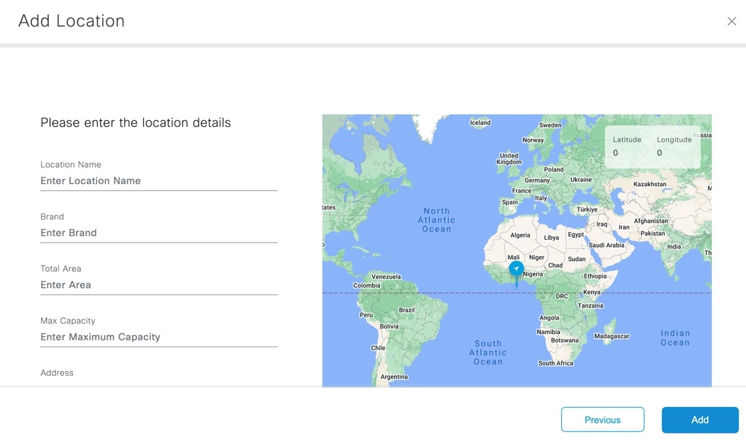
Figure 3. Add Location

Step 5

In the Add Location window, enter the following location details to add a new location:

  • Location Name: Name for the new location.

  • Brand: Brand for the new location.

  • Total Area: Total area details for the new location.

  • Max Capacity: Maximum capacity information for the new location.

  • Address: The address of the new location. You can manually enter the address or drag the marker to choose the address from map displayed on the right side.

  • Time Zone: Select the time zone from the drop-down list.

  • Latitude: Latitude of the new location.

  • Longitude: Longitude of the new location.

Step 6

Click Add.

A success message is displayed indicating that a new location is added. You can click Add Another Location if you want to add more locations manually.

Step 7

Click Done.

The Building section in the Locations tab displays the location details. The Summary section displays the details of the buildings, floors, missing location metadata information and locations that need review.


Update Location Information

The Locations tab displays an alert message if location metadata is missing for the imported location.

You can update location information as part of map preparation. You refine the building address, verify geo-coordinates, and save corrected metadata before proceeding to floor selection or map upload workflows.

Procedure


Step 1

Log in to Cisco Spaces.

Step 2

In the Cisco Spaces dashboard, click the Menu icon () and choose Setup > Locations and Maps.

The Locations and Maps window is displayed with the Locations tab selected.

Step 3

In the Buildings section, next to Essential Location Info field, click the Alert icon to update the missing location metadata.

The Update Location Info window is displayed.

Step 4

In the Update Location Info window, update the following location details as required:

  • Location Name: Name for the new location.

  • Brand: Brand for the new location.

  • Total Area: Total area details for the new location.

  • Max Capacity: Maximum capacity information for the new location.

  • Address: The address of the new location. You can manually enter the address or drag the marker to choose the address from map displayed on the right side.

  • Time Zone: Select the time zone from the drop-down list.

  • Latitude: Latitude of the new location.

  • Longitude: Longitude of the new location.

Step 5

Click Save.


Review Locations

In the Locations and Maps window, an alert message is displayed if the imported location hierarchies need review. You need to review the locations and need necessary actions.

During review, the system validates unsupported merge combinations and displays actionable error messages. The interface prevents unsupported merges such as Webex-to-Webex, Meraki-to-Meraki, certain same-source hierarchy merges, and floor merges that do not correspond to the correct building context.

If you must merge a floor, first complete the review and merge steps for the parent building. Then return to the floor-level review items. This process keeps the final hierarchy consistent and prevents invalid merges between floors or between floors and different buildings.

Procedure


Step 1

In the Locations and Maps window, click Preview to view and proceed with location reviews.

The Review Locations window displays all sources from which locations are imported, for example, Cisco Meraki or Catalyst Center. You can also view the number of sites, buildings and campuses imported for each location.

Step 2

Select the source location to review and click Next.

The Review Locations window displays the imported location hierarchy levels for the selected source in the left column and existing destination location hierarchy levels in the right column. Use the Search Locations field to search for specific locations.

Step 3

Use the options available in the Action drop-down list and select a recommended action to merge each level in the source location hierarchy with a relevant destination business hierarchy level in the right column.

By default, Cisco Spaces recommends some actions for reviewing the imported location hierarchy. The available actions are: Merge with, Accept, Create New and Delete.

  • The action that you opt for the highest node in the source location hierarchy is automatically cascaded over to the subsequent nodes.

  • You cannot delete a campus node from the source location hierarchy if the levels under the campus node are already merged with any relevant destination business hierarchy level.

  • You cannot merge a building from the source location hierarchy to a campus in the destination business hierarchy.

  • You can merge a site from the source location hierarchy to a campus in the destination business hierarchy.

  • If the name of the source location hierarchy matches with any business hierarchy available in Cisco Spaces Location Hierarchy, then Cisco Spaces automatically displays the matching destination levels, and you proceed with the merge action.

  • If the source location hierarchy is new, then select Create action to automatically create a new business hierarchy in Cisco Spaces Location Hierarchy.

Step 4

From the Existing Locations drop-down list, select the relevant destination level to merge and unify the imported location hierarchies from any source location with the business hierarchy available in Cisco Spaces Location Hierarchy.

The Existing Locations drop-down list displays all the destination nodes available in the Cisco Spaces Location Hierarchy. You can view the source from where the business hierarchy is imported in the drop-down list.

Step 5

Click Next.

The Merge Locations window displays the summary of the actions and its implications with respect to the associated analytics data. We recommend that you review this alert information before proceeding.

Note


If a location that you selected to be deleted includes rules associated with it, you cannot proceed with the delete action. You need to review the action and update your merge preferences accordingly.

If a location that you selected to be deleted includes reports associated with it, you can proceed with the delete action. The reports are generated again after the locations are merged.

Step 6

Click Agree and Continue.

The selected review actions are processed, and the location is marked as reviewed. If you select to merge the source location level with a relevant destination node, all the properties of the source location levels are applied to the destination node in the business hierarchy.


Add Network Map

Use the Network Maps tab to add a network map and view the locations with the network maps associated with it. You can import locations only if the source has network maps associated with it. Currently, Cisco Prime Infrastructure, Catalyst Center, Cisco Meraki and Cisco Connected Mobile Experiences includes network maps.

In addition to the basic add-network-map workflow, the current page supports filter-based validation of imported network map coverage. Use the Filter drawer to narrow the list by hierarchy, source, number of APs, and number of floors before taking action on a building.

If a location does not yet have a network map, use the row-level warning tooltip to open the upload or import path for that building.

Procedure


Step 1

Log in to Cisco Spaces.

Step 2

In the Cisco Spaces dashboard, click the Menu icon () and choose Setup > Locations and Maps.

The Locations and Maps window is displayed.

Step 3

Click Network Maps tab.

Step 4

Click Add Network Map.

The Upload Building Details window is displayed.

Step 5

Import the locations using the following methods that include network maps:

The imported location details are displayed in the Locations and Maps window under the Network Maps tab.

Step 6

Click Preview to view and proceed with location reviews. For more information, see Review Locations.

Step 7

(Optional) In the Network Maps tab, use the following options as required:

  • Export: Click to export the imported business location details into a Microsoft Excel file (.xls). You can click Download to download the same.

  • Recent Activity: Click to view the recent activity details. The Recent Activity slide-in window displays the following information:

    • File Name

    • User

    • Type

    • Time

    • Status

  • Filter: Click to view the filter options. In the Filter slide-in window that is displayed, choose the location from the Locations drop-down list and the required filter options and click Select to apply.


Import locations from Cisco CMX

Use the Import locations from CMX option to import locations from Cisco CMX. You must tether Cisco CMX with Cisco Spaces to import locations.

Procedure


Step 1

Log in to Cisco Spaces.

Step 2

In the Cisco Spaces dashboard, click the Menu icon () and choose Setup > Locations and Maps.

The Locations and Maps window is displayed.

Step 3

Click Network Maps tab.

Step 4

Click Add Network Map.

The Upload Building Details window is displayed with various methods to upload the locations.

Step 5

Click Import locations from CMX and click Next.

The Import Location Details window is displayed.

Step 6

(Optional) Click Learn how to tether CMX to view the instructions to tether Cisco CMX with Cisco Spaces. For more information, see Cisco CMX Tethering.

Step 7

In the Import Location Details window, click Next.

Step 8

Read the instructions to connect Cisco CMX and click Next.

The Connect your wireless network window is displayed. Use this option to connect to Cisco CMX.

Step 9

If you are already connected, proceed with adding locations using the Location Hierarchy.


Add Digital Map

Use the Digital Maps tab to add digital maps for buildings in your location hierarchy. You need to upload the Computer-aided design (CAD) file(s) for the floor to convert them into a three-dimensional floor plan.

The Summary area displays the number of buildings for which digital maps are imported, number of buildings for which map review is pending and number of buildings with errors.

The Buildings area displays the locations available.

Working with your building floor plans is more efficient than ever with the redesigned Digital Maps management. The new listing screen provides a floor-level view with contextual actions based on each floor’s status—from setting the building address to adding floors, uploading CAD files, and reviewing, editing, or publishing maps.

Granular per-floor statuses replace the earlier building-level view, and each floor can be reviewed and published independently on its own schedule.

Procedure


Step 1

Log in to Cisco Spaces.

Step 2

In the Cisco Spaces dashboard, click the Menu icon () and choose Setup > Locations and Maps.

The Locations and Maps window is displayed.

Step 3

Click Digital Maps tab.

Step 4

Select the building or floor you want to add digital maps.

Step 5

In the Actions column, click Add digital maps.

The Add Digital Map: Support DNA window is displayed.

  1. Read through the CAD file (.dwg) or Vector PDF related information displayed.

  2. Click Proceed.

Step 6

To confirm the address, complete these steps and click Confirm Address.

  1. To select the location, either enter the building name in the Search field or click directly on the map to place a marker.

  2. Alternatively, click and drag the marker to adjust the location on the map as needed.

    Verify that the building location on the map is correct.

    Note


    If you want to choose the location from the map displayed on the right panel, you need to provide permission to Cisco Spaces to use the current location to populate the geo-coordinates.

    Note


    If you have not added address details when adding digital maps, click Set address in the Actions section.

Step 7

(Optional) To add a new floor, click Add/update floors.

Step 8

Click Add new floor and enter these details:

  1. In theFloor Name: Enter the name of the new floor.

  2. In the Level Number: Select the level number of the new floor.

  3. In the Short Name: Enter the short name of the new floor.

Step 9

Click Save.

Step 10

Click the building drop-down list to view the floors.

Step 11

To add Add digital maps for the floors:

  1. Click Add digital maps.

  2. Click Proceed.

Step 12

Upload source files to use for Digital Maps generation. You can drag and drop files to the designated upload section or click Choose file to browse locally and upload them.

  • The upload wizard is simplified to a single step — update floor metadata and upload CAD files for multiple floors in one shot. Level numbers can now be edited during upload. AI-generated previews are typically available within 15 minutes, so you can catch issues early — and cancel processing if needed.

  • A warning message is displayed if the file is already exists.

  • (Optional) Choose the reason from Reason for force submission drop-down list.

  • Use the Supplementary information for processing the CAD file section to enter upload information.

We recommend that CAD file must contains all layers, such as architecture, furniture, names, and IDs for all the elements to convert. Only the elements with names or IDs can support sensor assignments.

Note

 
  • Upload only one CAD file per floor. Cross references (XREFs) are not supported.

  • The supported file types are ZIP, AutoCAD Drawing file (DWG), AutoCAD Drawing Interchange File (DXF), Portable Document Format (PDF).

  • You can upload one file per floor or use Bulk Upload to upload multiple source files together. The page displays per-floor upload progress and lets you cancel or replace an upload if needed.

    If you perform a bulk upload after individual floor files are already staged, a confirmation pop-up appears. Confirm the bulk action to replace the existing staged files for that workflow.

    When you upload a file identical to a previously processed one, the interface requires you to provide a re-processing reason and additional comments. Select a reason, enter comments explaining the correction, and optionally upload supporting evidence such as reference files or explanatory documents. You can upload supporting files from the floor card when more context is needed for re-processing.

    For buildings in review or draft state, you can use View/Edit or Review from the window to reopen the editor. When a building has an in-progress PRO map workflow, the contextual menu also shows Preview option, allowing you to inspect the current generated state.

Note

 
  • After uploading and confirming files, the workflow presents contextual actions based on the building state and license type. These actions include Save, Submit, Publish this Building, Skip this Building, Back to Preview, Resume, Discard changes, Cancel processing, and others.

  • Users can add, edit, or remove floor details at the building level.

Step 13

Click Submit.

A success message appears, along with a Note.

Step 14

Click Done.

The CAD file(s) and the location metadata are processed, Then, the map is digitized. The processing status appears in the Digital Map processing status section.

(Optional) After some time, the message AI preview available appears in the Digital Map processing status section.

(Optional) Click View.

Step 15

Click Review if the map is processed and ready to review.

Step 16

In the Review Digital Maps window, select the building you want to review and click Next.

The digitized map is displayed.

Step 17

(Optional) Select a floor or space and click to update them if required.

A pop-up window is displayed, and you can edit the name or update the type category.

Step 18

Click Publish this Building.

The digitized map is published and available for other applications to use them, for example, Cisco Smart Workspaces, Environmental Metrics app and so on.

In Cisco Spaces Location Hierarchy, for a selected location, digital maps are displayed by default if the location has digital maps.

Click Skip this building if you want to discard the changes.

Additionally, use the View History option to inspect building-level map workflow events and Delete Digital Map option to remove an existing digital map when you have the appropriate permissions and state conditions are met.


Catalyst Center Map Export

In Locations & Maps, the Digital Maps feature (Setup > Locations & Maps > Digital Maps) lets you export building maps (published version) to Cisco Catalyst Center.

The option to export is available only for buildings with a published map.

The map export feature works only if the APs are placed under the Setup > Device Placement option.

Export Building Maps to Catalyst Center

Before you begin

The Export option is not available in these scenarios:

  • When using an older version of the Cisco Spaces dashboard UI. We recommend that you switch to the beta version of the dashboard to access this feature.

    For locations where Access Points (APs), configured via the Device Placement feature, are not placed using PRO maps.

    The Rich Map must not be in any of these statuses:

    • Processing

    • Error

    • Cancelled

    • Review

    • Deleted

To support network planning and monitoring, you can export the published version of a building’s digital map from Cisco Spaces to Catalyst Center.

Use the Export to Catalyst Center feature in Cisco Spaces to seamlessly transfer building maps to Catalyst Center.

Use the Export to Catalyst Center to export building maps (published version) to Catalyst Center.

You start the export from the building row action menu after the building map is in a supported published state.

Procedure


Step 1

Log in to Cisco Spaces.

Step 2

In the Cisco Spaces dashboard, click the Menu icon () and choose Setup > Locations and Maps.

The Locations and Maps window is displayed with the Locations tab selected.

Step 3

Click the three dots next to a building and select Export to Catalyst Center to process the map.

When the export starts, the UI shows a processing state while it prepares the ZIP package. After the export completes successfully, the Download option is displayed.

Note


If the export cannot complete for the selected building, an error message is displayed indicating that the building is not currently supported for this export action.

Step 4

Click Download to save the processed digital map (in ZIP format) for the selected building.

Step 5

Follow the instructions in the pop-up window to import the map hierarchy into Catalyst Center.