Cisco AI POD with VAST Data for Training and Fine-Tuning Deployment Guide
Available Languages
Bias-Free Language
The documentation set for this product strives to use bias-free language. For the purposes of this documentation set, bias-free is defined as language that does not imply discrimination based on age, disability, gender, racial identity, ethnic identity, sexual orientation, socioeconomic status, and intersectionality. Exceptions may be present in the documentation due to language that is hardcoded in the user interfaces of the product software, language used based on RFP documentation, or language that is used by a referenced third-party product. Learn more about how Cisco is using Inclusive Language.
- US/Canada 800-553-2447
- Worldwide Support Phone Numbers
- All Tools
 Feedback
 Feedback
In partnership with:

About the Cisco Validated Design Program
The Cisco Validated Design (CVD) program consists of systems and solutions designed, tested, and documented to facilitate faster, more reliable, and more predictable customer deployments. For more information, go to: https://www.cisco.com/go/designzone.
Executive Summary
Cisco AI PODs are modular, pre-validated infrastructure solutions designed to support the full AI lifecycle, including training, fine-tuning, and inference workloads. Built on Cisco UCS compute, Cisco Nexus networking, and industry-leading GPUs, Cisco AI PODs provide a scalable, secure, and operationally efficient foundation for enterprise AI deployments in data center and edge environments. The architecture takes a building-block approach using Scale Unit Types, enabling organizations to start with deployments of 32-, 64-, or 128-GPU clusters. These foundational building blocks can then scaled incrementally and predictably to support 256, 512, or higher GPU clusters as requirements evolve. Cisco AI PODs are validated to simplify design, deployment, and day-to-day operations while supporting a broad range of AI use cases.
The solution is based on one of several design options presented in the Cisco AI POD for Enterprise Training and Fine-Tuning Design Guide. The implementation details enable infrastructure engineers and AI/ML practitioners to quickly build, configure, and operationalize a high-performance AI cluster.
Within this architecture, Cisco E-Box, based on Cisco UCS C225 M8 servers, provides a flexible, CPU-optimized compute platform for AI infrastructure services, data processing, and supporting control-plane functions. Cisco AI PODs enable centralized lifecycle management through Cisco Intersight and Nexus Dashboard, delivering consistent provisioning, automation, and operational visibility across the AI infrastructure. This approach supports AI workloads such as large language models (LLMs), generative AI, retrieval-augmented generation (RAG), and analytics, while allowing configurations to be aligned with performance, scalability, and cost requirements.
When combined with VAST Data, Cisco AI PODs deliver a validated, high-performance storage architecture optimized for data-intensive AI workloads. VAST Data provides a single, global namespace with file and object access, enabling efficient data sharing across AI training and inference workflows without data duplication. Deployed on Cisco UCS-based platforms, the VAST Data architecture enables independent scaling of performance and capacity, delivering predictable low latency and high throughput as AI environments expand.
The integrated solution of Cisco AI PODs, Cisco Nexus Dashboard Cisco E-Box (Cisco UCS C225 M8), and VAST Data provides a cohesive AI-ready infrastructure that simplifies data access, supports efficient GPU utilization, and reduces operational complexity. Centralized management through Cisco Intersight, combined with VAST Data’s parallel data services, enables consistent operations, enterprise-grade security, and high availability. Backed by Cisco Validated Designs and partner validation, this solution helps organizations deploy and scale AI workloads with reduced risk and increased confidence.
This deployment guide, together with the AI POD Design Guide and the GitHub repo for this solution, serves as the complete AI POD Cisco Validated Design for Enterprise Training and Fine-tuning. The complete portfolio of Cisco AI POD CVDs is available here: Cisco Validated Design Zone for AI-Ready Infrastructure.
Solution Overview
This chapter contains the following:
Cisco AI PODs integrated with VAST Data offers a comprehensive, scalable infrastructure designed to accelerate AI and machine learning workloads. This solution combines Cisco UCS servers, Cisco Nexus switches, and VAST Data storage—with the advanced GPU-accelerated compute capabilities of Cisco AI PODs. Together, they provide a validated, high-performance platform optimized for AI lifecycle tasks such as training, inferencing, and deployment. Leveraging technologies like Cisco UCS X-Series modular systems, NVIDIA GPUs, and software platforms including NVIDIA Base Command Manager, this integrated environment simplifies AI infrastructure management through Cisco Intersight. The combined solution delivers high-speed networking, persistent storage, and automation to reduce complexity and enable enterprises to efficiently scale AI workloads with security and operational visibility.
The intended audience of this document includes but is not limited to IT architects, sales engineers, field consultants, professional services, IT managers, partner engineering, and customers who want to take advantage of an infrastructure built to deliver IT efficiency and enable IT innovation.
This document provides deployment guidance around setting up Cisco AI PODs with Cisco UCS C885A M8 servers along with VAST Data AI training and fine-tuning use cases. This document introduces various design elements and explains various considerations and best practices for a successful deployment.
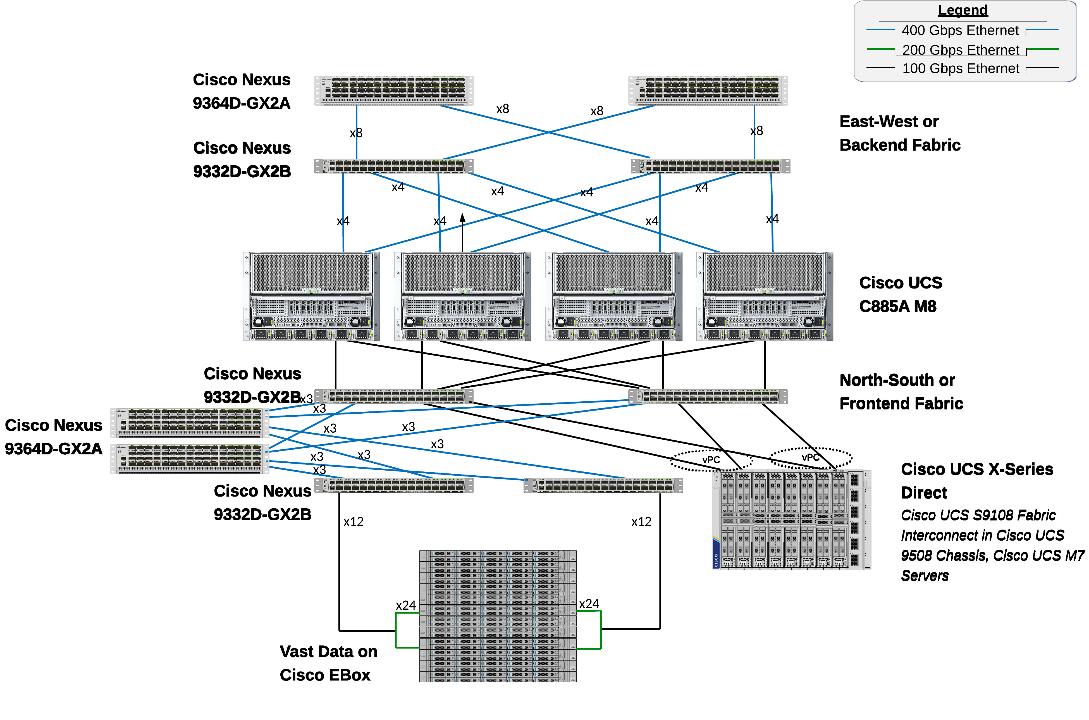
The Cisco AI POD solution in this document is a fully integrated solution with high-density compute, high-performance networking, scale-out storage, and a robust software stack, designed for Enterprise Training and Fine-Tuning. This guide provides detailed implementation guidance for deploying a 32-GPU cluster and covers the configuration of compute, network, storage, and the software stack required to support distributed training and fine-tuning workloads. It also includes the platform level validations to ensure that the integrated subsystems are functioning as expected. The integrated solution consists of the following components:
● Cisco UCS C885A M8 Servers: Four nodes, each equipped with eight NVIDIA H200 GPUs (SXM) and dual AMD EPYC processors. These servers provide the primary compute power for distributed training and fine-tuning. Within the server, GPUs are interconnected via NVIDIA NVLink, delivering 900 GB/s of bidirectional bandwidth per node.
● Cisco UCS X-Series Direct: A dedicated management cluster used to host the management services.
● Network: Dual-fabric architecture (Backend and Frontend) utilizing Cisco Nexus 9000 Series switches, managed and deployed using Cisco Nexus Dashboard.
● Backend (East-West) Fabric: Four Cisco Nexus 9332D-GX2B switches connected in a two-tier spine-leaf Clos-based topology. This fabric provides a dedicated, non-blocking 400GbE environment for GPU-to-GPU communication via RoCEv2.
● Frontend (North-South) Fabric: Four Cisco Nexus 9332D-GX2B switches, two as compute + management leaf switches and two as dedicated storage leaf switches. This fabric provides connectivity for cluster management, storage I/O, and user access.
● VAST Data on Cisco EBox: VAST Data platform is deployed on Cisco EBox based on Cisco UCS C225 M8 servers, provides a CPU-dense, flexible platform well suited for AI data services, metadata processing, and infrastructure control functions, enabling efficient integration of VAST Data within Cisco AI POD architectures aligned to NVIDIA reference designs.
● Cisco Intersight: Provides hardware health monitoring and visibility for the Cisco UCS C885A M8 GPU nodes while managing the complete lifecycle of the Cisco UCS X-Series management cluster.
● Cisco Nexus Dashboard: Serves as the centralized automation and operations platform for both the Backend and Frontend network fabrics.
● NVIDIA AI Enterprise (NVAIE): A comprehensive suite of AI software that includes optimized drivers, CUDA libraries, and the NVIDIA Collective Communications Library (NCCL) required for performant distributed training.
Solution Design
This chapter contains the following:
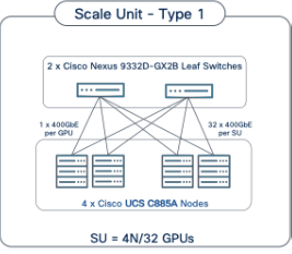
The Cisco AI POD architecture is a modular, building-block design using Scale Unit Types that can be predictably and incrementally scaled to support large GPU clusters as described in the Cisco AI POD for Enterprise Training and Fine-Tuning Design Guide. This implementation is based on Scale Unit - Type 1 (see Figure 1), a 32-GPU cluster using Cisco UCS dense GPU servers, Cisco Nexus networking, VAST Data on Cisco EBox, integrated into a unified infrastructure stack.
Cisco AI PODs with VAST Data meets the following general design requirements:
● Resilient design across all layers of the infrastructure with no single point of failure
● Scalable design with the flexibility to add compute capacity, storage, or network bandwidth as needed
● Modular design that can be replicated to expand and grow as the needs of the business grow
● Flexible design that can support different models of various components with ease
● Simplified design with the ability to integrate and automate with external automation tools
● Cloud-enabled design which can be configured, managed, and orchestrated from the cloud using GUI or APIs
The following figure illustrates the logical infrastructure stack, validated in this solution:
For the AI POD networking and server design, please refer to the Cisco AI POD for Enterprise Training and Fine-Tuning Design Guide. This document focuses on the VAST Data design integrated with Cisco AI PODs.
The storage system and architecture are critical components of AI training, fine-tuning, and inference environments. AI workloads require extremely high performance, linear scalability, and secure shared access to data in order to efficiently read large training datasets and write model checkpoints, logs, embeddings, and other artifacts throughout the AI lifecycle. A primary storage requirement for AI training is very high-throughput, low-latency sequential reads, as massive datasets must be rapidly streamed into GPU memory at the start of each training epoch, while also supporting highly parallel metadata operations.
The VAST Data platform is deployed on Cisco EBox leveraging Cisco UCS C-Series servers. The solution implements a disaggregated, shared-nothing architecture that separates compute (VAST CNodes) from storage capacity (VAST DNodes) both deployed on each Cisco EBox node This architecture enables independent scaling of performance and capacity while presenting a single global namespace across the entire cluster, simplifying data access for AI workloads running on Cisco AI PODs.
Each VAST Data EBox node is connected redundantly to a pair of Cisco Nexus 9332D-GX2B leaf switches using high-speed Ethernet connectivity. The existing deployment is configured with 200GbE front-end networking, including NFSv3, NFSv4.x, and NFS over RDMA (NFS-RDMA) for ultra-low-latency data access, as well as S3 object access to the same underlying data without data duplication. When equipped with NVIDIA ConnectX 7 adapters, VAST Data enables high-bandwidth, RDMA-accelerated data paths optimized for GPU-dense environments.
VAST Data’s parallel, distributed metadata architecture eliminates traditional file system bottlenecks, allowing all clients to access all storage nodes concurrently. This design enables massive parallel I/O, consistent low latency, and linear performance scaling as additional CNodes and DNodes are added. AI workloads benefit from parallel data access patterns without the constraints of controller-based storage architectures.
The VAST Data platform supports GPU-accelerated workloads using NVIDIA GPUDirect Storage, enabling direct data movement between VAST storage and GPU memory, bypassing CPU bottlenecks and reducing latency. This capability is particularly beneficial for large-scale AI training and fine-tuning workloads deployed on Cisco UCS C885A GPU servers, where maximizing GPU utilization is critical.
Aligned with NVIDIA Enterprise Reference Architecture (ERA) guidance, the VAST Data on Cisco UCS design enables scalable AI infrastructure by independently scaling VAST nodes alongside Cisco UCS GPU compute nodes. This architecture provides a high-performance, resilient, and operationally simple storage foundation for AI training, fine-tuning, and inference within Cisco AI POD environments.
This section provides the specific hardware and software details used in this deployment (Table 1).
| Component (PID) |
Quantity |
Notes |
| UCS GPU Cluster |
||
| Cisco UCS C885A M8 Servers |
4 Nodes |
|
| NVIDIA H200 SXM5 GPUs |
32 GPUs (total), 8 GPUs per server |
141GB of HBM3e memory each |
| NVIDIA ConnectX-7 NICs |
8 NICs per server |
1x 400GbE NIC for connecting to backend fabric |
| NVIDIA BlueField-3 NICs |
1 NIC per server |
2x 200GbE NIC for connecting to frontend fabric |
| Backend Fabric |
||
| Cisco Nexus 9332D-GX2B |
2 Spine, 2 Leaf Switches |
400GbE fabric |
| Frontend Fabric |
||
| Cisco Nexus 9364D-GX2A |
2 Spine Switches |
400GbE from Spine to Leaf |
| Cisco Nexus 9332D-GX2B |
2 Compute, 2 Storage Leaf Switches |
200GbE to compute, 2x 200GbE to each VAST EBox node |
| UCS Management Cluster |
||
| Cisco UCS X-Series Direct |
|
|
| UCS X9508 Chassis (UCSX-9508) |
1 |
|
| UCS X Direct 100G (UCSX-S9108-100G) |
2 |
|
| VIC 15231 MLOM (UCSX-ML-V5D200G) |
3 (2x100G mLOM) |
To connect to frontend fabric |
| Storage |
||
| VAST Data |
12 x Cisco EBox nodes |
2x 200G from each node for VAST internal network 2x 200G from each node for VAST external network |
| Software |
||
| NVIDIA AI Enterprise (NVAIE) |
|
Licenses required |
| Cisco Nexus Dashboard |
3 |
3-node physical cluster |
| Cisco Intersight |
N/A |
SaaS platform |
| VAST Data |
N/A |
VAST Data storage and compute Licenses |
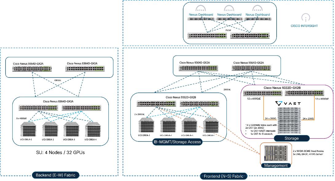
The physical topology for AI PODs with VAST Data and NVIDIA Base Command Manager is as follows:
● Cisco UCS C885A M8 servers each with 8 NVIDIA H200 GPUs
● Cisco UCS X9508 Chassis with eight Cisco UCS X210c Compute Nodes for management and supporting services
● Fifth-generation Cisco UCS X-Series Direct Fabric Interconnects 9108 to support 100GbE connectivity from various components
● High-speed Cisco NX-OS-based Nexus 9332D-GX2B and 9364D-GX2A switching design to support 100GE and 400GE connectivity
● VAST Data on Cisco UCS, comprising of 12x Cisco UCS C225 M8N nodes certified for Cisco EBox
The software components of this solution consist of:
● Cisco Intersight to deploy, maintain, monitor and support the Cisco UCS server components
● Cisco Nexus Dashboard to deploy, maintain, and support the Cisco Nexus Switching Fabrics
● NVIDIA Base Command Manager to orchestrate training workloads on Ubuntu
● VAST Data on Cisco EBox
AI PODs with VAST Data Topology
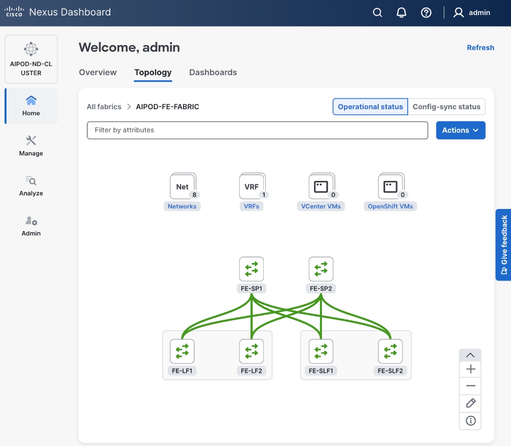
Figure 2 shows various hardware components and the network connections for AI PODs with VAST Data.
The key functional building blocks of this design are:
● Backend (East-West) Fabric is a dedicated, non-blocking 400GbE fabric optimized for inter-node GPU-to-GPU communication. The fabric is built using a minimum of 2 leaf switches and 2 spine switches. It can be scaled to support a max. cluster size of 128 GPUs by adding leaf pairs and larger clusters by adding spine pairs.
● Frontend (North-South) Fabric is a 400GbE-capable spine-leaf fabric providing connectivity for management, user access, and storage. This fabric uses 2 spine switches and 4 leaf switches as listed below. This fabric can also be scaled as needed by adding or upgrading links or adding switch pairs.
◦ Compute/Management Leaf Pair: Provides 200GbE connectivity for the Cisco UCS C885A nodes and Cisco UCS X-Series Direct management clusters.
◦ Dedicated Storage Leaf Pair: Provides 400GbE connectivity to VAST Data on Cisco EBox , isolating storage I/O from other frontend traffic.
● Scale Unit - Type 1: This building block consists of four Cisco UCS C885A M8 servers connected to two backend leaf switches, forming a 32-GPU cluster. The Cisco UCS C885A M8 servers connect to the backend and frontend fabrics using E-W NICs (8 per server) and N-S NICs (1 per server), respectively. This design can scale by adding more scale units of the same or different types. Additional N-S NICs can also be added as needed — for example, to provide dedicated, high-speed access to storage.
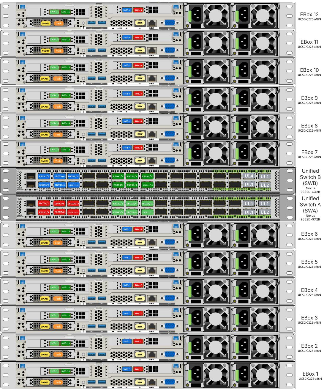
● VAST Data on Cisco EBox leveraging Cisco UCS C225 M8 servers is configured in Intersight Standalone mode with a minimum of twelve (12) nodes for VAST cluster.
Figure 3 details a high-level deployment of VAST on Cisco UCS C225 M8 (EBox) nodes.
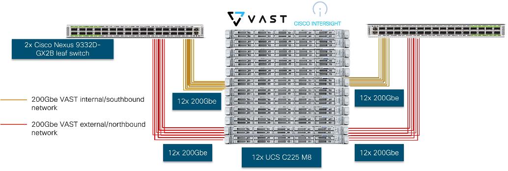
The deployment includes:
● 12 x Cisco UCS C225 M8 servers (EBox) certified for VAST
● 2 x Cisco Nexus 9332D-GX2B or Nexus 9364D-GX2A (leaf switches)
● 2 optics
◦ Optics (passive cables)
- 24x QDD-2Q200-CU3M (400G QSFP56-DD to 2x200G QSFP56 Copper Breakout Cable, 3m)
- 4x QDD-400-CU3M (400G Passive Cable, 3m)
◦ Optics and Fiber
- On 400G switch side, 24x QDD-400G-DR4-S (400G QSFP-DD Transceiver, MPO-16 APC, 100m OM4 MMF),
- On CX7 side, 48x QSFP-200G-SR4-S (200GBASE SR4 QSFP56 Transceiver, MPO, 100m over OM4 MMF)
- MPO breakout cable (Breakout MMF patchcord: MPO-16 to 2X MPO-12)
Note: For certified optics see: https://tmgmatrix.cisco.com.
The physical connectivity of the AI POD is designed to maximize throughput and minimize latency. For the 32-GPU cluster, a 2-way rail-optimized topology is implemented. This section details the Connectivity Design and port mapping used in this validated design.
Backend (East-West) Connectivity
The backend fabric is engineered for non-blocking connectivity between GPU servers in the cluster. This is achieved by ensuring that the number of uplinks from leaf-to-spine are equal in number and bandwidth to the number of downlinks from leaf-to-UCS server. As shown in Figure 4, the total number of 400GbE host-facing ports on the leaf switches (32 ports across 4 nodes) is matched by an equal number of 400GbE uplinks to the spine layer, ensuring that GPU synchronization traffic never encounters oversubscription bottlenecks.
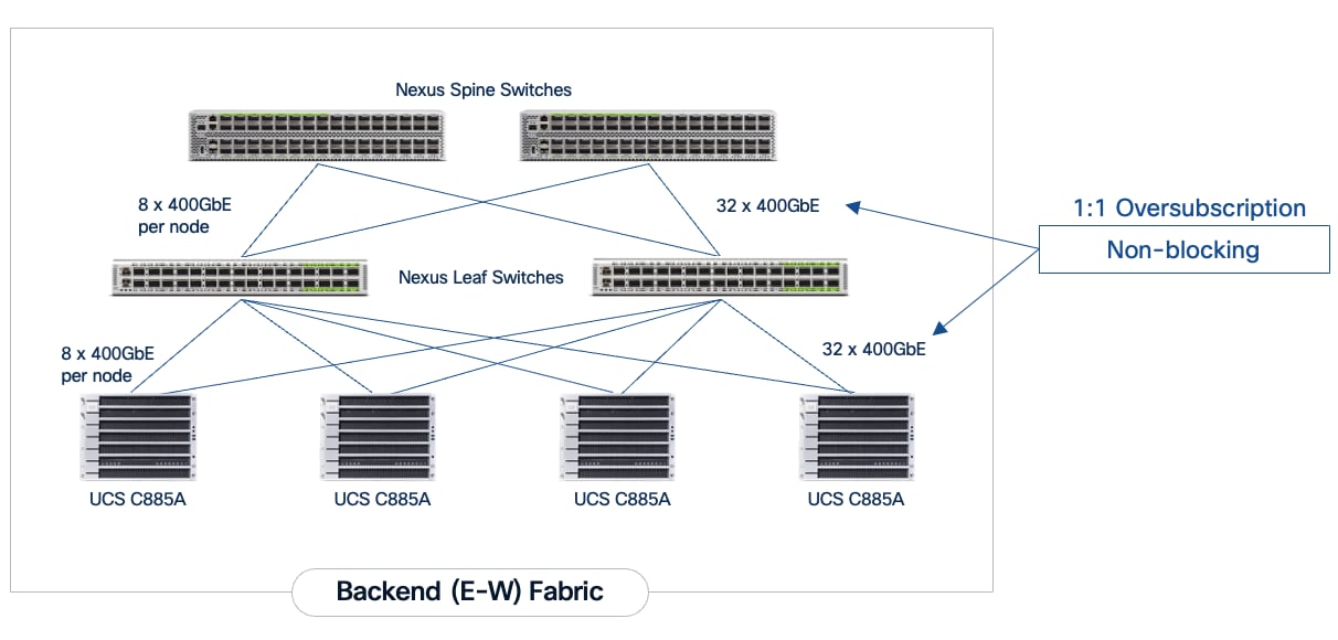
Each Cisco UCS C885A node is connected to the two leaf switches in the fabric using a 2-way rail-optimized topology. To achieve this, the 8 x 400GbE connections from each server are distributed across the two leaf switches in the Scale Unit – Type 1. This ensures that GPUs of the same rank, across all nodes in the Scale Unit, connect to the same physical leaf switch, minimizing the network hops required for critical collective operations.
Table 2. Backend Fabric Connectivity
| From |
GPU NICs |
To |
Port Speed |
Connectivity |
| UCS C885A (1-4) |
NICs 1, 3, 5, 7 |
Leaf Switch 1 |
400GbE |
Access VLAN |
| UCS C885A (1-4) |
NICs 2, 4, 6, 8 |
Leaf Switch 2 |
400GbE |
Access VLAN |
| Leaf Switch 1 |
16 x Uplinks – evenly distributed across Spines |
Spine Switch 1-2 |
400GbE |
Routed |
| Leaf Switch 2 |
16 x Uplinks – evenly distributed across Spines |
Spine Switch 1-2 |
400GbE |
Routed |
Each Cisco UCS C885A server was equipped with 8 x NVIDIA ConnectX-7 (1 x 400GbE) NICs, one per GPU for connecting to the backend fabric. NVIDIA BlueField-3 NICs can also be used as E-W NICs.
Figure 5 illustrates the backend topology used to validate this solution.
Frontend (North-South) Connectivity
The frontend fabric provides the data path for cluster management, storage, services and external access. Each Cisco UCS C885A server connects to the compute/leaf switches in the frontend fabric using 2 x 200GbE links. The uplinks to the frontend fabric are configured as a LACP bond for high availability. The management and storage access traffic are deployed in different VLANs and trunked on this bonded interface.
The Cisco UCS X-Series management cluster also connect to the same compute leaf switches that the Cisco UCS C885A servers connect to. These leaf switches also provide access to Cisco Intersight and Nexus Dashboard for managing this environment.
VAST Data on Cisco EBox, in this design connects to dedicated frontend storage leaf switches using multiple high bandwidth 400GbE links to support concurrent NFS and S3 traffic.
Table 3. Frontend Fabric Connectivity
| From |
To |
Connectivity |
Traffic Type |
| UCS C885A Nodes |
Compute Leaf Pair |
2-Port LACP Bond |
VLAN Trunk (Management & Storage) |
| UCS X-Series Direct |
Compute Leaf Pair |
Multi-Port LACP Port-Channel |
VLAN Trunk (Management/Control) Plane) |
| VAST Data |
Storage Leaf Pair |
VAST unified connectivity (VAST internal network and VAST Client Network on same laf pair switches) |
VLAN Trunk (NFS & S3) |
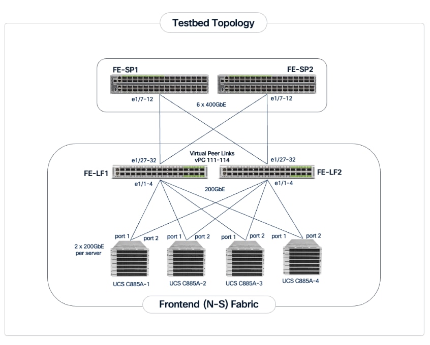
The detailed connectivity from UCS C885A nodes to the compute/management leaf pair is shown in Figure 6.
Connectivity for VAST Data on Cisco EBox
In the deployment both the internal/southbound network ports (from network adapter in PCI Slot 3) and the external/customer/northbound network ports (from network adapter in PCI slot 1) are connected to the same pair of 400G Cisco Nexus switches.
Figure 7 details the connectivity of Cisco UCS C225 M8 server (EBox) with a single pair of Cisco Nexus 9332D-GX2B switches.
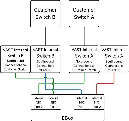
The following are the labelling instructions for Figure 8:
● SWA is defined as switch A.
● SWB is defined as switch B.
● Ports marked in blue and red are used for VAST internal network.
● Ports marked in light and dark green are used for connectivity to customer network or external network.
● Number of uplinks or connections to spine switches is dependent on the number of EBox connected to the switch pair. If you have 12 EBox nodes, you need 4x 400G uplinks from each switch.
● In this deployment, a 400G to 2x 200G breakout cable (QDD-2Q200-CU3M) was used allowing connections to 400G ports on switch side and 200G ports on CX7 adapter for each EBox. For example:
◦ EBox1 and EBox2 both marked with SWA-11 connects to Port 11 of Switch A
◦ EBox1 and EBox2 both marked with SWB-11 connects to Port 11 of Switch B
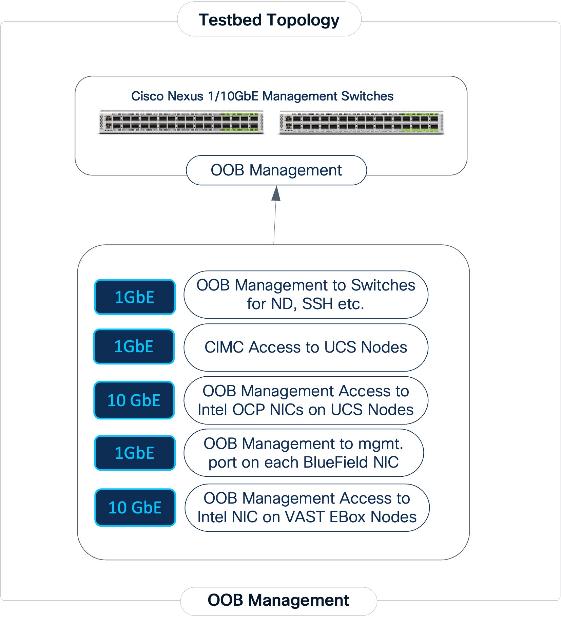
Out-of-Band Management Connectivity
All switches and servers in the topology are connected to dedicated Out-of-Band (OOB) management network and for initial provisioning via CIMC and Redfish and as a backup path to access the devices.
The VAST EBox nodes management ports (MGMT/enp65s0f0) are also connected to same Out-of-Band (OOB) management network.
This section provides the specific design details for the compute, network, and storage sub-systems for solution validated in Cisco labs.
Backend (East-West) Fabric
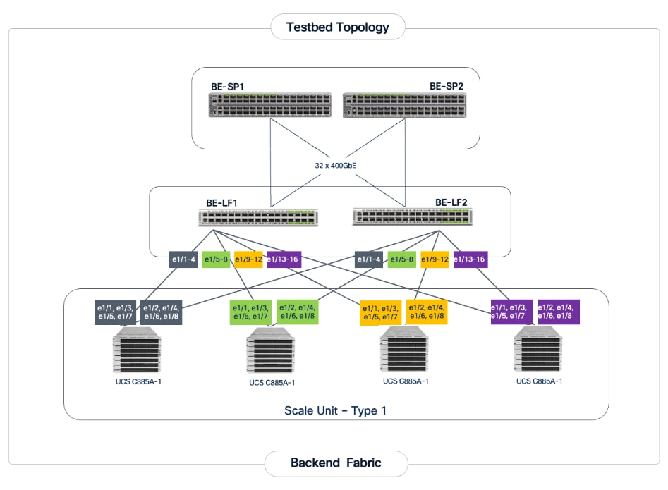
The backend fabric is a lossless, low-latency, high-throughput ethernet fabric, designed to support the stringent performance requirements of GPU-to-GPU RDMA communication. This fabric is exclusively for inter-node RDMA over Ethernet (RoCEv2) GPU communication. As stated earlier, this fabric is deployed as a two-tier spine-leaf Clos topology using a MP-BGP VXLAN EVPN architecture, providing a multi-tenant environment with flexible support for both scalable Layer 2 and Layer 3 overlays across an IP underlay. In this design, a layer 2 overlay where all 32 GPUs reside in a single logical broadcast domain, simplifying the communication patterns required by AI frameworks.
Table 4. UCS GPU Node Connectivity to Backend Fabric
| From |
E-W NIC |
Connectivity |
To |
Logical Connectivity |
| UCS C885A Nodes (1-4) |
1/1, 1/3, 1/5, 1/7 (Access Ports) |
Rail Optimized (2-way) |
Backend Leaf 1 |
Access VLAN (3590) mapped to L2 VNI (33590) |
| UCS C885A Nodes (1-4) |
1/2, 1/4, 1/6, 1/8 (Access Ports) |
Rail Optimized (2-way) |
Backend Leaf 2 |
Access VLAN (3590) mapped to L2 VNI (33590) |
The fabric is deployed using pre-built fabric templates available in Nexus Dashboard, implementing a prescriptive, best-practice design for the backend fabric as shown in Figure 10. Though the templates implement a specific configuration, organizations still have the flexibility of customizing some or all aspects of the template as needed.
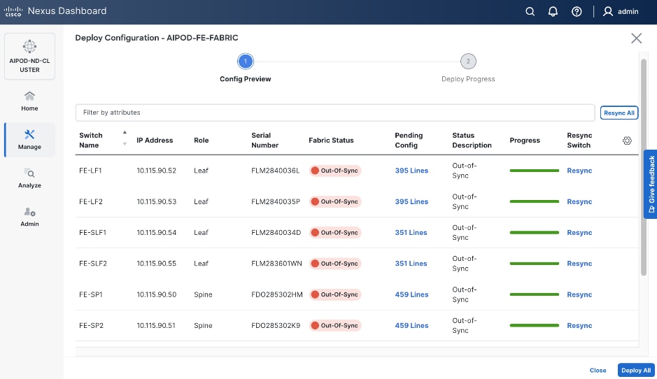
When the connectivity is in place, these templates enable the fabric to be provisioned and deployed quickly. The 2-spine, 2-leaf backend fabric in this design with over 400 lines of configuration (see Figure 11) was deployed in minutes.
The design uses QoS features outlined below to create a lossless environment for RoCEv2 traffic, preventing packet drops during bursty synchronization events. The QoS policy is implemented (default) by the deployed AI/ML template.
● Traffic Classification: A dedicated class-map (COS 3) is used to identify RoCEv2 synchronization traffic.
● Priority Flow Control (PFC): PFC is enabled on COS 3 to provide hop-by-hop flow control. This ensures that in the event of congestion, the switch can signal the upstream device to pause transmission, preventing packet drops.
● Explicit Congestion Notification (ECN): ECN is configured with specific WRED (Weighted Random Early Detection) thresholds. This allows the Nexus switches to mark packets when buffers begin to fill, signaling the GPU endpoints to throttle their transmission rate before PFC is triggered, maintaining a smooth data flow.
● MTU: A global MTU of 9000 (Jumbo Frames) is applied across all links in the fabric to ensure large AI data packets are processed efficiently without fragmentation.
In this implementation, the default QoS policy in the deployed template was modified to support this design. The key changes are:
● MTU for PFC3 traffic changed from X to Y.
● QoS Bandwidth Allocation changed to allocate more bandwidth for RDMA traffic since this backend fabric is dedicated to this type of traffic. The only other traffic in this network is a small amount of control and management traffic.
The Cisco UCS GPU nodes are added to the Red Hat OpenShift cluster as worker nodes. The networking connectivity to the backend fabric is deployed and provisioned using Kubernetes NMState Operator and NVIDIA’s Network Operator. The GPU Direct RDMA and overall deployment of GPU is implemented using NVIDIA’s GPU Operator . All operators are available from Red Hat’s Operator Hub, directly accessible from OpenShift cluster console.
The Layer 2 (overlay) connectivity between the 4 Cisco UCS C88A M8 nodes across the backend fabric requires the following changes on the Cisco UCS nodes.
Frontend (North-South) Fabric
The frontend fabric provides Cisco UCS GPU nodes with connectivity to management, services, storage, and to other networks within and external to the enterprise. In a hybrid deployment, inferencing traffic from users and application also use this fabric.
Similar to the backend fabric, the frontend is also deployed in a two-tier spine-leaf Clos-based topology, using a MP-BGP VXLAN EVPN architecture. Both Layer 2 and Layer 3 overlays are used to logically segment the different types of traffic on this network.
Quality of Service (QoS), including PFC and ECN, was deployed to ensure that NFS RDMA traffic to VAST Storage was prioritized across the frontend fabric when there is congestion.
Table 5 lists VLANs configured for setting up the environment along with their usage.
| VLAN ID |
Name |
Usage |
IP Subnet used in this deployment |
| 2* |
Native-VLAN |
Use VLAN 2 as native VLAN instead of default VLAN (1) |
|
| 550* |
OOB-MGMT-VLAN |
Out-of-band management VLAN to connect management ports for various devices |
10.115.90.0/26; GW: 10.115.90.1 |
| 703 |
Ubuntu-BareMetal-MGMT |
Routable VLAN used for Ubuntu management |
10.115.90.64/26; GW: 10.115.90.126 |
| 3051 |
NFS |
Used for Ubuntu storage |
192.168.51.0/24 |
| 10 |
VAST-Discovery_VLAN10 |
Used for discovery of nodes during VAST cluster install |
|
| 3056 |
VAST-Client_VLAN_3056 |
VAST external storage network |
192.168.56.24 |
| 69 |
VAST-Storage_VLAN_69 |
VAST internal network |
|
Table 6 lists the VMs or bare metal servers necessary for deployment as outlined in this document.
| Virtual Machine Description |
VLAN |
IP Address |
Comments |
| AD1 |
703 |
10.115.90.123 |
Hosted on pre-existing management infrastructure |
| AD2 |
703 |
10.115.90.124 |
Hosted on pre-existing management infrastructure |
| NVIDIA Base Command Head Node |
703 |
10.115.90.115 |
Hosted on pre-existing management infrastructure |
Table 7 lists the software revisions for various components of the solution.
| Layer |
Device |
Image Bundle |
Comments |
| Compute |
Cisco UCS C885A M8 Firmware Package |
1.1(0.250025) |
Upgrades all server components |
| Cisco UCS X210c M6 |
5.3(5.250021) |
||
| Cisco UCS Fabric Interconnect 9108 100G |
4.3(5.240162) |
||
| Network |
Cisco Nexus Dashboard |
4.1.1g |
|
| Cisco Nexus 9332D-GX2B NX-OS |
10.4(5) |
||
| Cisco Nexus 9364D-GX2A NX-OS |
10.4(5) |
||
| Storage |
VAST OS |
vast-os-12.14.27-1879753 |
|
| VAST VMS |
release-5.3.3-hf5-2058254 |
||
| Software |
NVIDIA H200 GPU Driver - Ubuntu |
570.133.20 |
|
| NVIDIA H200 GPU CUDA Version-Ubuntu |
12.8 |
Network Switch Configuration
This chapter contains the following:
Cisco Nexus Frontend Fabric Setup
Cisco Nexus Backend Fabric Setup
In this lab configuration, Cisco Nexus Dashboard is used to create and configure the Backend and Frontend Fabrics. Nexus Dashboard is available in both physical and virtual form factors. In this lab configuration, three Nexus Dashboard physical nodes were installed into a cluster. See Nexus Dashboard Capacity Planning and Cisco Nexus Dashboard Data Sheet to determine the form factor and cluster size for your deployment, then install Nexus Dashboard
Cisco Nexus Frontend Fabric Setup
In this setup, the Nexus Frontend Fabric consisted of 2 spine and 4 leaf switches. This fabric was cabled as listed in Table 3. The fabric switch details are listed in Table 8.
Table 8. Frontend Fabric Switch Details
| Switch |
Role |
OOB IP |
Firmware |
Model |
| FE-LF1 |
Leaf |
10.115.90.52 |
10.4(5) |
Cisco Nexus 9332D-GX2B |
| FE-LF2 |
Leaf |
10.115.90.53 |
10.4(5) |
Cisco Nexus 9332D-GX2B |
| FE-SLF1 |
Storage Leaf |
10.115.90.54 |
10.4(5) |
Cisco Nexus 9332D-GX2B |
| FE-SLF2 |
Storage Leaf |
10.115.90.55 |
10.4(5) |
Cisco Nexus 9332D-GX2B |
| FE-SP1 |
Spine |
10.115.90.50 |
10.4(5) |
Cisco Nexus 9364D-GX2A |
| FE-SP2 |
Spine |
10.115.90.51 |
10.4(5) |
Cisco Nexus 9364D-GX2A |
Physical Connectivity
Note: Follow the physical connectivity guidelines for AIDPODs with VAST Data as explained in Connectivity Design section.
Initial Configuration of Switches
The following procedures describe this basic configuration of the Cisco Nexus frontend fabric switches for use in the existing environment. This procedure assumes the use of Cisco Nexus 9000 10.4(5), the Cisco suggested Nexus switch release at the time of this validation.
Procedure 1. Set up initial configuration from a serial console
Step 1. Set up the initial configuration for each backend fabric switch as listed in Table 8.
Step 2. Configure the switch.
Note: On initial boot, the NX-OS setup automatically starts and attempts to enter Power on Auto Provisioning.
Abort Power On Auto Provisioning [yes - continue with normal setup, skip - bypass password and basic configuration, no - continue with Power On Auto Provisioning] (yes/skip/no)[no]: yes
Disabling POAP.......Disabling POAP
poap: Rolling back, please wait... (This may take 5-15 minutes)
---- System Admin Account Setup ----
Do you want to enforce secure password standard (yes/no) [y]: Enter
Enter the password for "admin": <password>
Confirm the password for "admin": <password>
Would you like to enter the basic configuration dialog (yes/no): yes
Create another login account (yes/no) [n]: Enter
Configure read-only SNMP community string (yes/no) [n]: Enter
Configure read-write SNMP community string (yes/no) [n]: Enter
Enter the switch name: <nexus-hostname>
Continue with Out-of-band (mgmt0) management configuration? (yes/no) [y]: Enter
Mgmt0 IPv4 address: <nexus-out_of_band_mgmt0-ip>
Mgmt0 IPv4 netmask: <nexus-mgmt0-netmask>
Configure the default gateway? (yes/no) [y]: Enter
IPv4 address of the default gateway: <nexus-mgmt0-gw>
Configure advanced IP options? (yes/no) [n]: Enter
Enable the telnet service? (yes/no) [n]: Enter
Enable the ssh service? (yes/no) [y]: Enter
Type of ssh key you would like to generate (dsa/rsa) [rsa]: Enter
Number of rsa key bits <1024-2048> [2048]: Enter
Configure the ntp server? (yes/no) [n]: Enter
Configure default interface layer (L3/L2) [L2]: Enter
Configure default switchport interface state (shut/noshut) [noshut]: Enter
Enter basic FC configurations (yes/no) [n]: n
Configure CoPP system profile (strict/moderate/lenient/dense) [strict]: Enter
Would you like to edit the configuration? (yes/no) [n]: Enter
Step 3. Review the configuration summary before enabling the configuration:
Use this configuration and save it? (yes/no) [y]: Enter
Step 4. Repeat this procedure for all switches listed in Table 8.
Deploy Frontend Fabric Using Nexus Dashboard
The procedures outlined in this section will use Cisco Nexus Dashboard (ND), specifically the fabric templates provided by ND, to deploy the frontend (FE) fabric in the AI POD solution. The frontend fabric is a 2-tier, 3-stage spine-leaf Clos topology, built using Cisco Nexus 9000 series data center switches. Once the fabric is deployed, ND will be used to provision connectivity between various infrastructure components connected to the frontend fabric. The Cisco UCS GPU servers in the AI POD training cluster will use the frontend (N-S) NIC to connect to the FE fabric.
The procedures in this section will:
● Deploy a VXLAN EVPN fabric on the frontend leaf and spine switches, connected in a 2-tier spine-leaf topology.
● Enable Virtual Port Channel (vPC) peering on compute/management leaf pairs and storage leaf pairs in the frontend fabric.
● Provision connectivity to UCS servers that will be used to host the control plane and workload management components for the AI workloads running on UCS GPU servers.
● Provisioning external connectivity from the frontend fabric to other enterprise internal and external networks. This includes connectivity to Cisco Intersight, and other SaaS services used in the AI POD solution.
● Provision any connectivity required to bring up the storage system.
● Enable connectivity between UCS management and storage, as well as from UCS GPU nodes to storage.
Procedure 1. Deploy VXLAN EVPN fabric on the two-tier spine and leaf switches
Step 1. From a web browser go to the management IP of any node in the Nexus Dashboard cluster. Log in using the admin account.
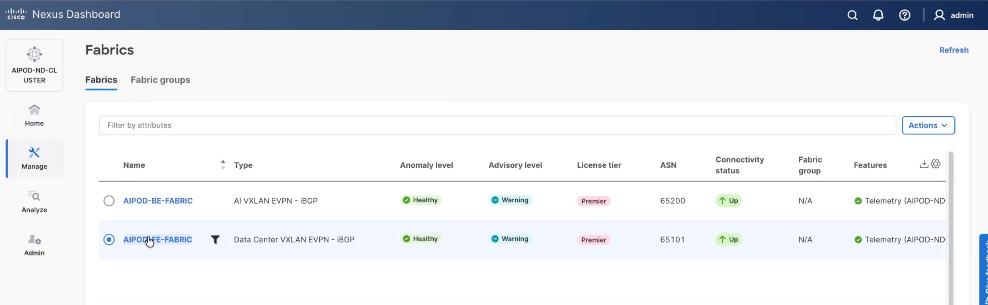
Step 2. From the left navigation menu, go to Manage > Fabrics.
Step 3. Click Actions and select Create Fabric from the drop-down list.
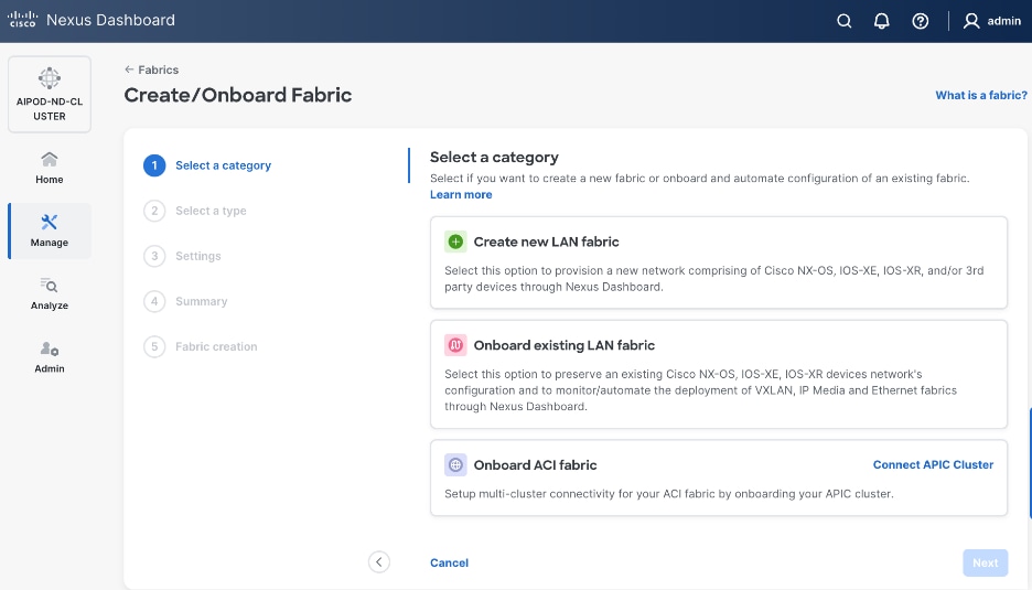
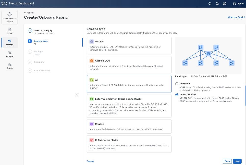
Step 4. Select Create new LAN fabric. Click Next.
Step 5. Select VXLAN and radio button for Data Center VXLAN EVPN for the fabric type. Click Next.
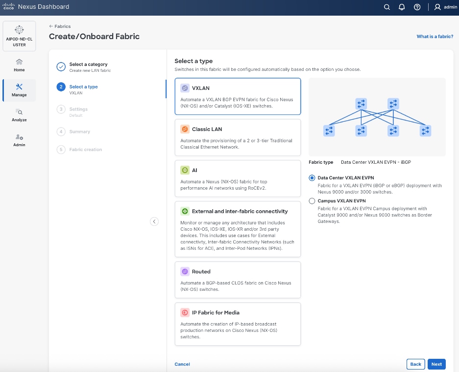
Step 6. For Configuration Mode, keep the Default option. Specify Name, Location, and BGP ASN for fabric. Also select the Licensing tier for fabric from the options available. Premier is required for advanced network analytics and day 2 operations. Click the ? icon to see the features available in each tier.
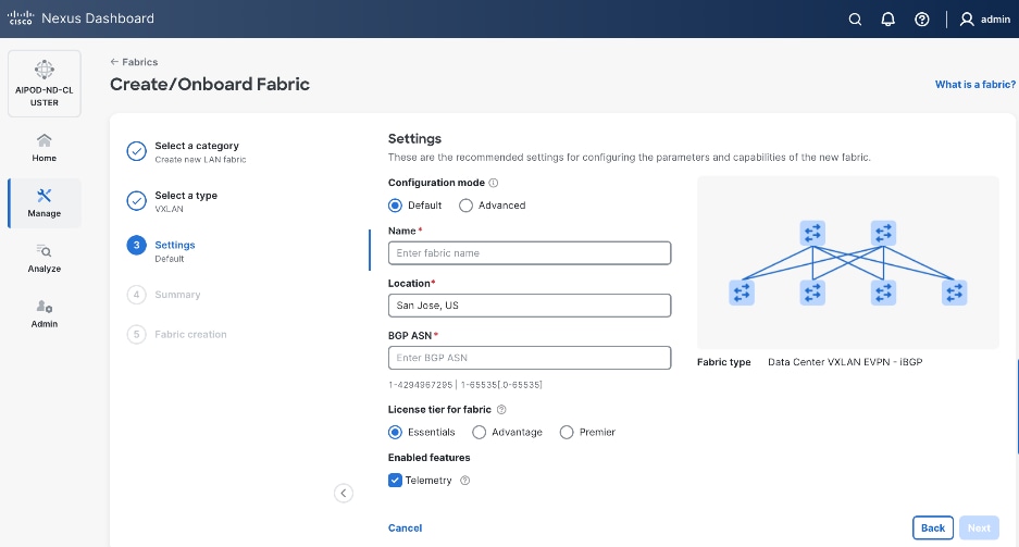
Step 7. Click Next.
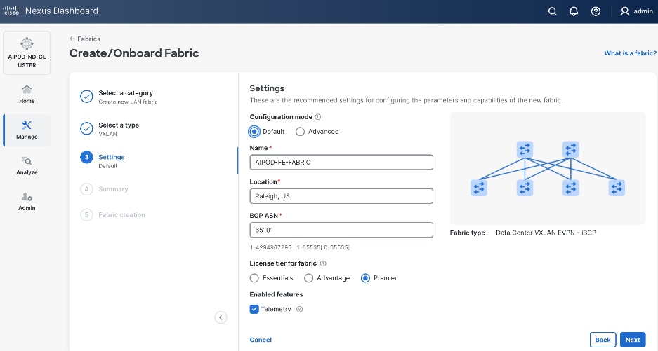
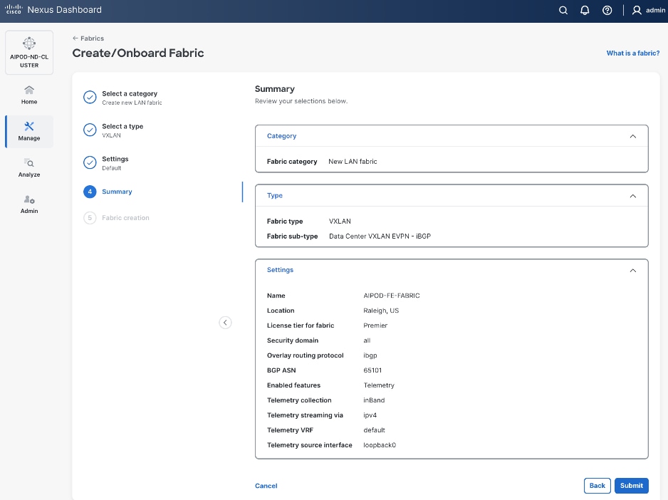
Step 8. In the Summary view, verify the settings and click Submit.
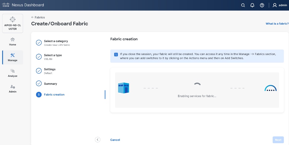
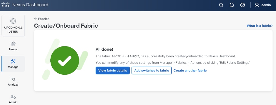
When Fabric Creation completes, you should see the following:
Step 9. Select Manage > Fabrics and then select the FE fabric. From the Actions drop-down list, select Edit fabric settings. Select the Fabric management tab and the Manageability tab. Add the NTP Server IPs and the NTP Server VRF (management) and click Save.
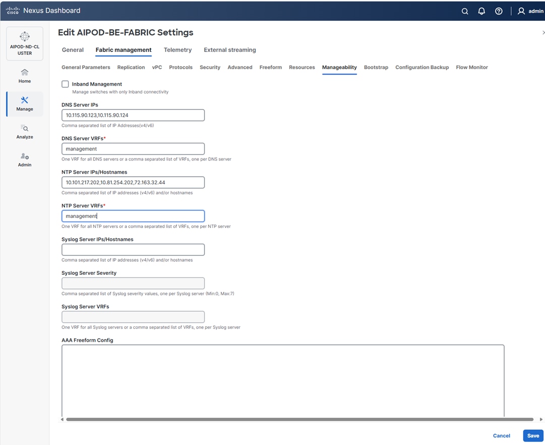
Note: The above screenshot and the following screenshot show the BE fabric but are the same for the FE fabric.
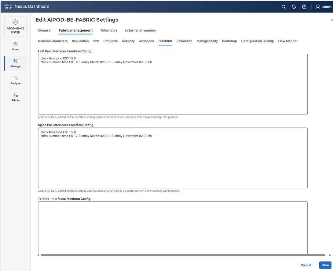
Step 10. Select the Freeform tab and optionally enter the info shown in the screenshot modified for your timezone. Click Save.
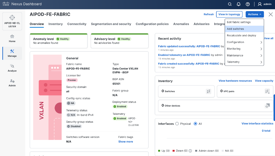
Step 11. If you want to add switches without a reload, click View fabric details. Select Fabric Management > Advanced tabs and scroll down to find the field for Add switches without Reload and change setting to enable. Click Save, followed by Got it in the pop-up window.
Step 12. From the Manage > Fabrics view, click the fabric name to add switches to the fabric.
Step 13. Click Actions and select Add Switches from the drop-down list.
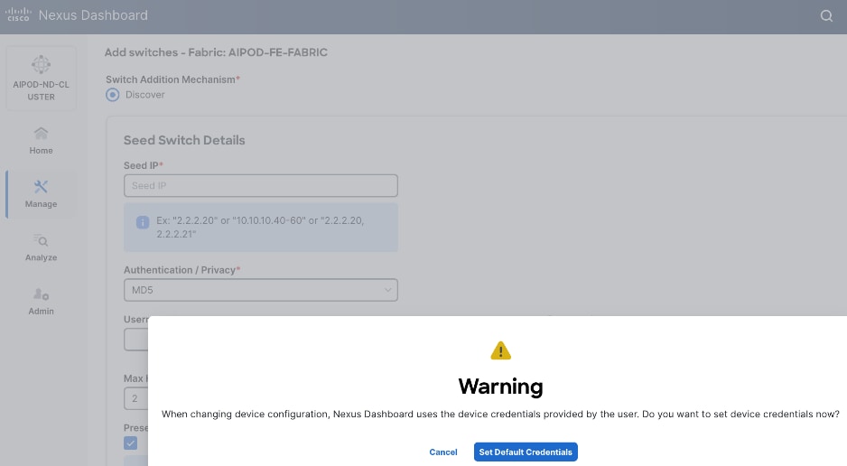
Step 14. In the pop-up window, click Set Default Credentials.
Step 15. Specify Username and Password. Click Save.
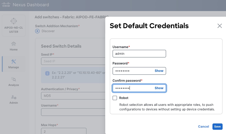
Step 16. Click Ok.
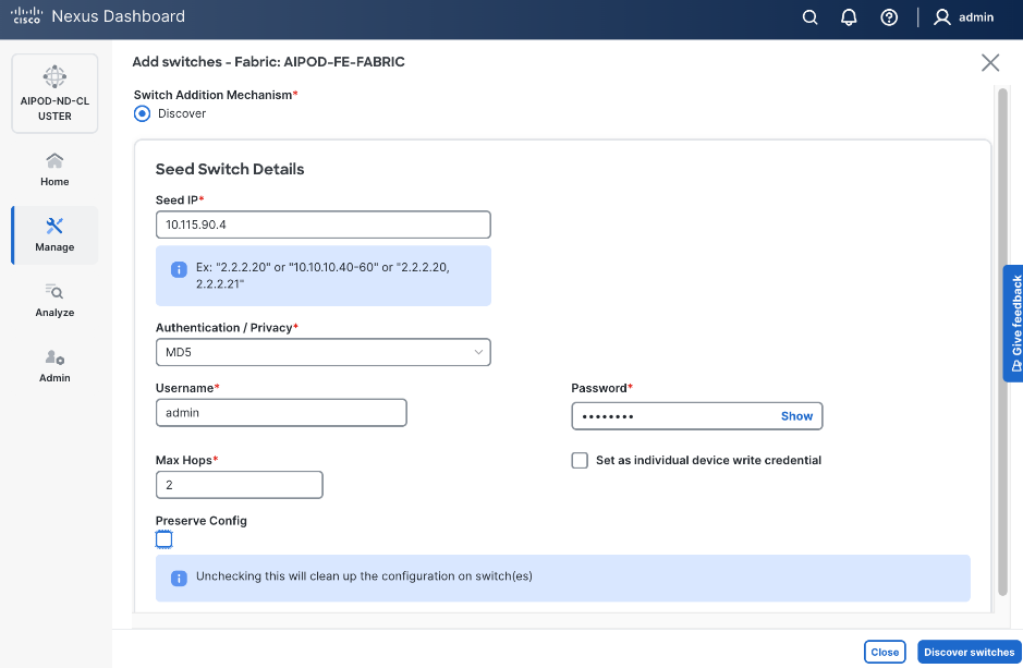
Step 17. Specify Seed IP, Username and Password. Adjust Max hops as needed. Click Discover Switches.
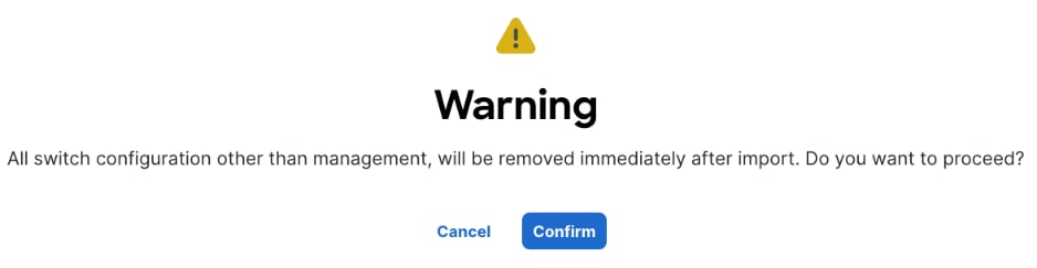
Step 18. Click Confirm in the pop-up Warning.
Step 19. Filter the discovered switch list as needed to view just the switches you want to add.
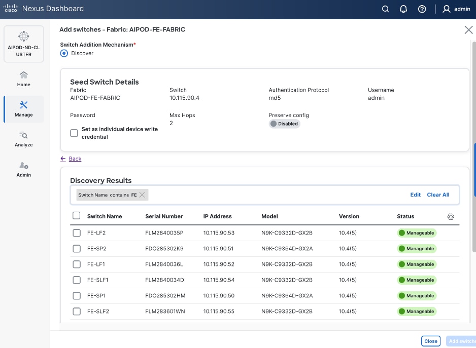
Step 20. Select all switches to be added. Click Add switches.
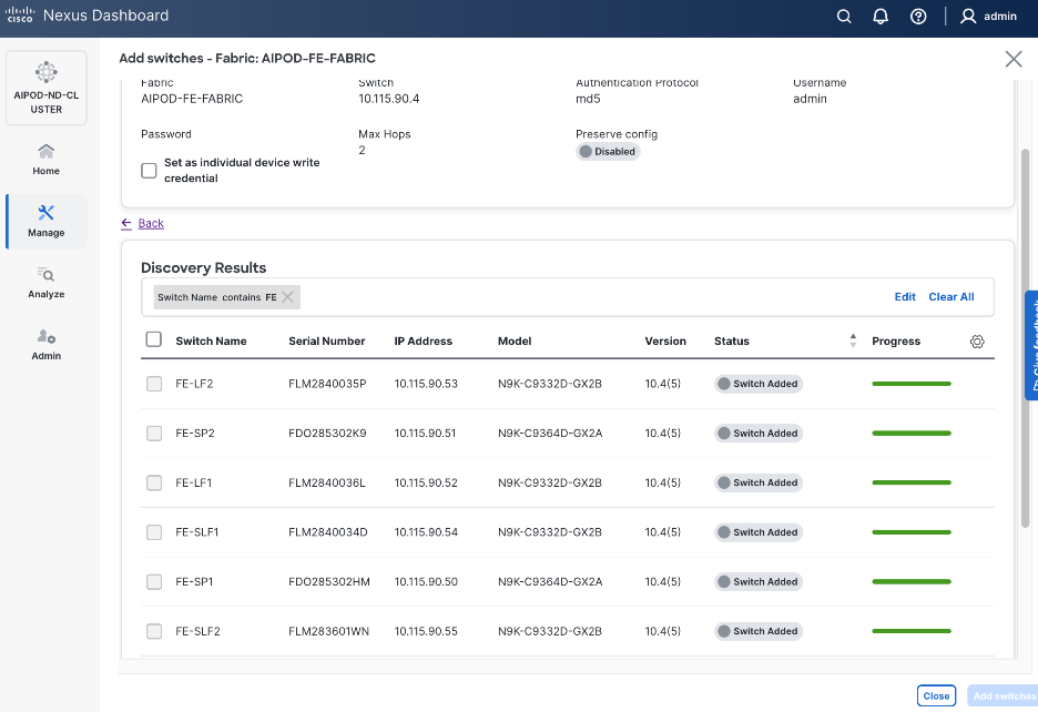
Step 21. Click Close when all switches have been added.
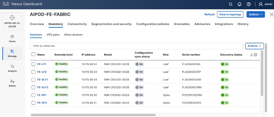
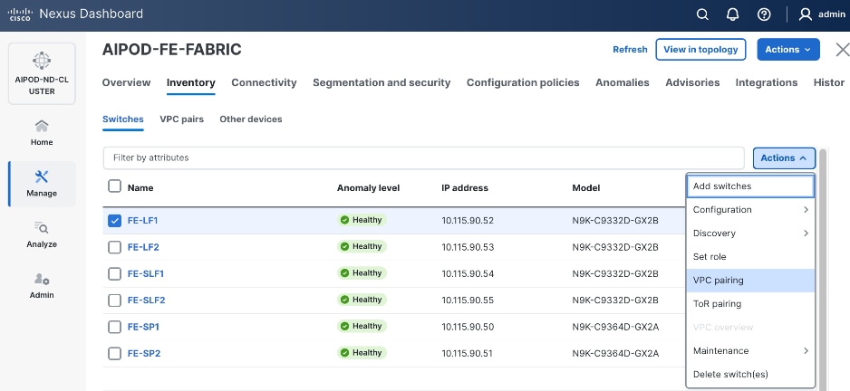
Step 22. From the Manage > Fabrics, select the fabric and click the Inventory tab.
Step 23. For each switch in the list, verify Role is correct. To change the role, select the switch and then click the lower Actions button and select Set role from the drop-down list.
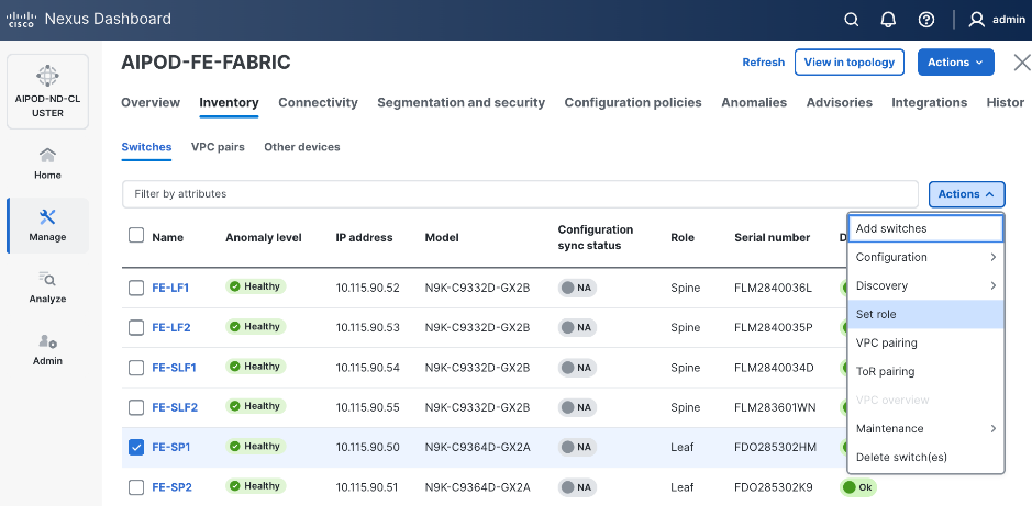
Step 24. In the Select Role pop-up window, select the correct role from the list and click Select.
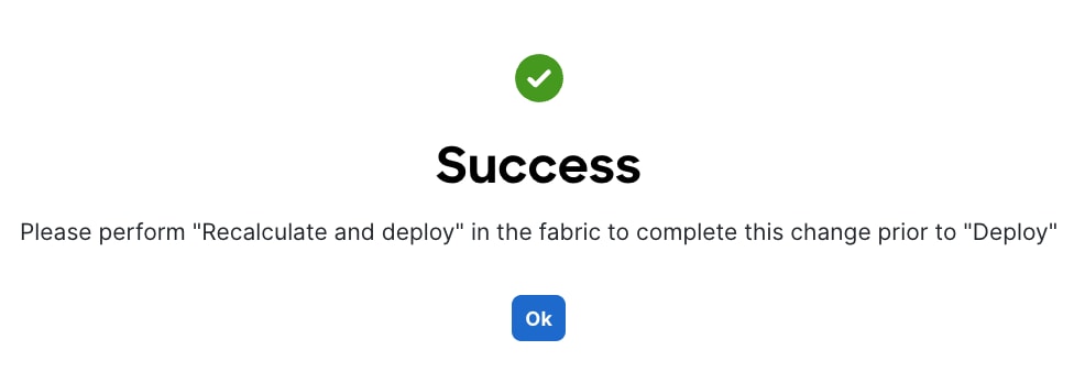
Step 25. Click OK in the pop-up warning to perform Recalculate and deploy to complete the change.
Step 26. Repeat steps 1 – 25 to select and confirm the role for all switches in the fabric.
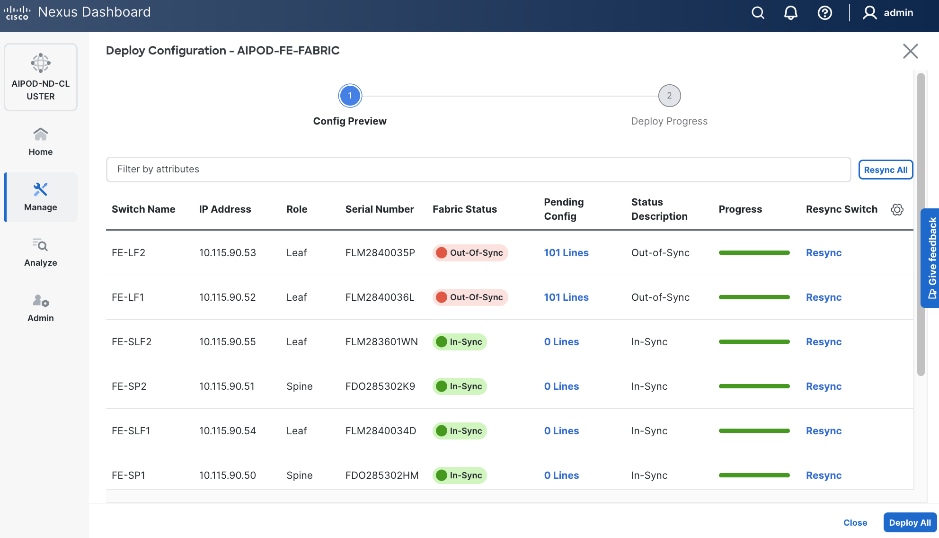
Step 27. Click the upper Actions button and select Recalculate and deploy from the drop-down list. If it says one is already in progress, wait a few minutes and repeat the steps. You should see the Fabric as Out-of-sync with some Pending Config (lines of config) change.
Step 28. Click Deploy All.
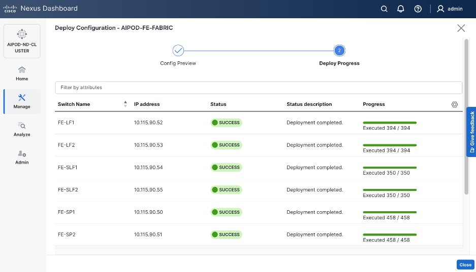
Step 29. Click Close.
Step 30. ND will identify issues in hardware, connectivity, software and so on, reflected by the Anomaly level. To view the flagged anomalies, go to Anomalies. Address each anomaly to prevent issues later, either by resolving them or acknowledging them.
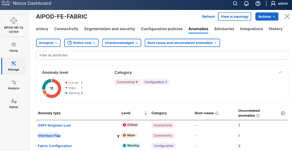
Step 31. Review the Advisories and resolve or acknowledge them.

Step 32. Evaluate and upgrade to Cisco recommended Nexus OS release.
Step 33. Start attaching compute, storage, and other end devices to the cluster.
Enable vPC Pairing on Compute/Management Leaf Switches in the FE Fabric
To enable vPC pairing on the compute/management in the FE fabric, follow the procedures below.
Procedure 1. Enable vPC pairing for compute/management leaf switches in the FE fabric
Step 1. From a web browser go to Nexus Dashboard. Use the management IP of any node in the ND cluster. Log in using admin account.
Step 2. From the left navigation menu, go to Manage > Fabrics.
Step 3. Select the FE fabric and click the Inventory tab.
Step 4. To enable VPC pairing on the leaf switches that connect to UCS compute (GPU and management) nodes, select the first leaf switch in the leaf pair.
Step 5. Click the lower Actions button and select VPC pairing from the drop-down list.
Step 6. Select the VPC peer switch for the first compute/management leaf. Enable Virtual Peerlink.
Step 7. Click Save.
Step 8. Click OK in the Success pop-up window.
Step 9. Select the two leaf switches in the vPC pair that are now Out-of-sync from the configuration change. Click the Actions button and select Recalculate and deploy from the drop-down list.
Step 10. Click Deploy All.
Step 11. When the configuration deployment completes successfully, click Close.
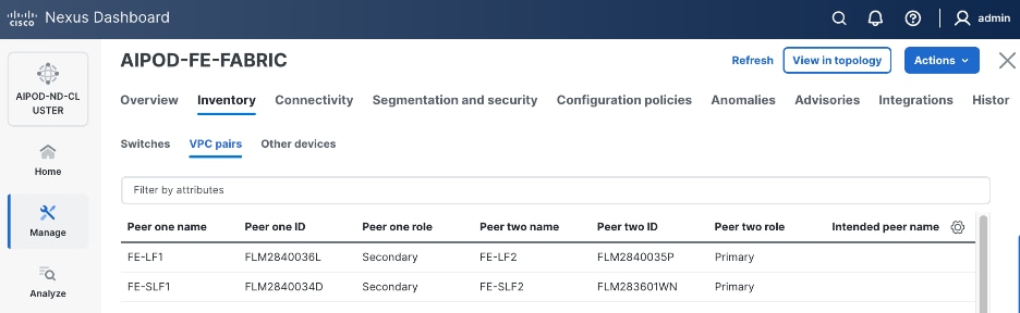
Step 12. From the Inventory tab, go to VPC pairs tab to see the newly created vPC pair.
Enable vPC Pairing on Storage Leaf Switches in the Frontend Fabric
To enable vPC pairing for the storage leaf switches in the FE fabric, follow the procedures below.
Procedure 1. Enable vPC pairing for storage leaf switches in the FE fabric
Step 1. Repeat the steps in the previous procedure to configure storage leaf switches in the FE fabric as vPC peers.
Step 2. From the Inventory tab, go to VPC pairs tab to see the newly created vPC pairs.
Step 3. From the navigation menu, go to Manage > Fabric and select the FE fabric and then the Topology tab, you should now see the 2 Leaf switch pairs grouped in a box, indicating they are vPC peers.
Modify QoS Policy on FE fabric (VAST Data)
Assumptions and Prerequisites
Assumes that you have selected the AI Fabric template with default QoS policy enabled. This section describes how to modify this default policy for the software version used in this CVD.
Setup Information
Table 9. Setup Information for BE Fabric QoS
| Parameter Type |
Parameter Name | Value |
Parameter Type/Other Info |
| QoS Policy Template |
|
|
| Default/Original Policy Template Name |
400G | AI_Fabric_QOS_400G |
|
| New Policy Template Name |
VAST_UNIFIED_QOS_200G |
|
| PFC MTU |
9216 |
Default for this release: 4200 |
| MTU for c-8q-nq3 |
9216 |
Default for this release: 4200 |
Deployment Steps
To change the QoS policy deployed in the frontend fabric, follow the procedures below, using the setup information listed in Table 9.
Procedure 1. Create new template from default QoS policy template
Step 1. From a web browser go to Cisco Nexus Dashboard. Use the management IP of any node in the ND cluster. Log in using admin account.
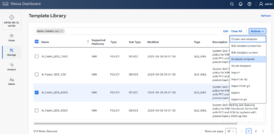
Step 2. Go to Manage > Template Library.
Step 3. Filter on QOS in top search bar.
Step 4. Select the default QoS policy that was applied when the BE fabric was deployed using the default AI fabric template.
Step 5. Click Actions.
Step 6. Select Duplicate template from the drop-down list.
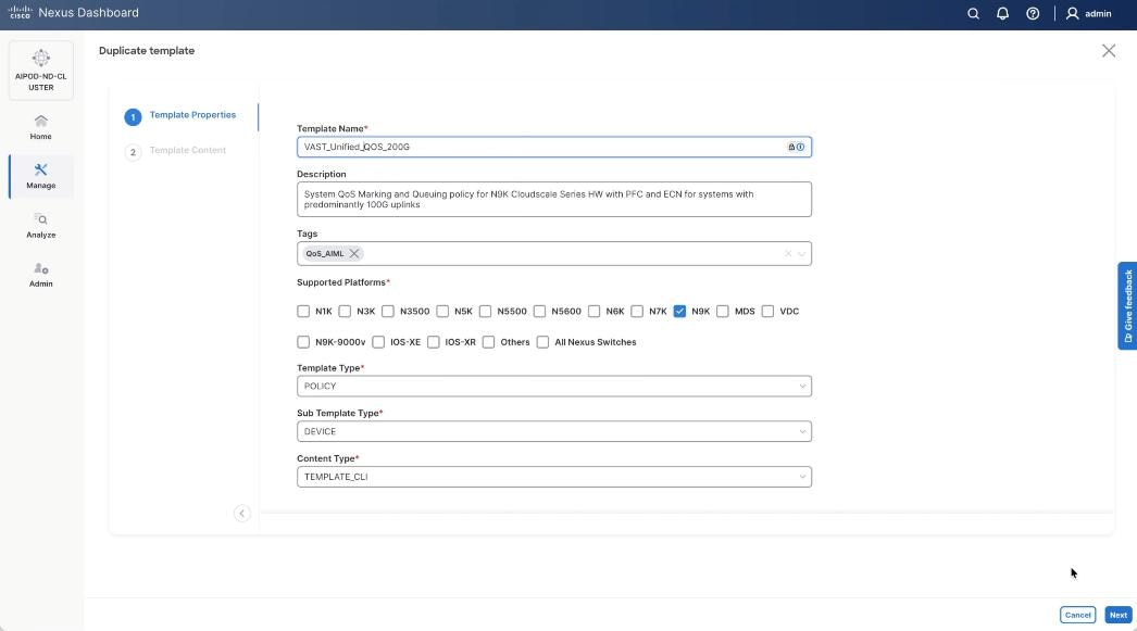
Step 7. In the Template Properties section, specify a new name for the QoS policy template.
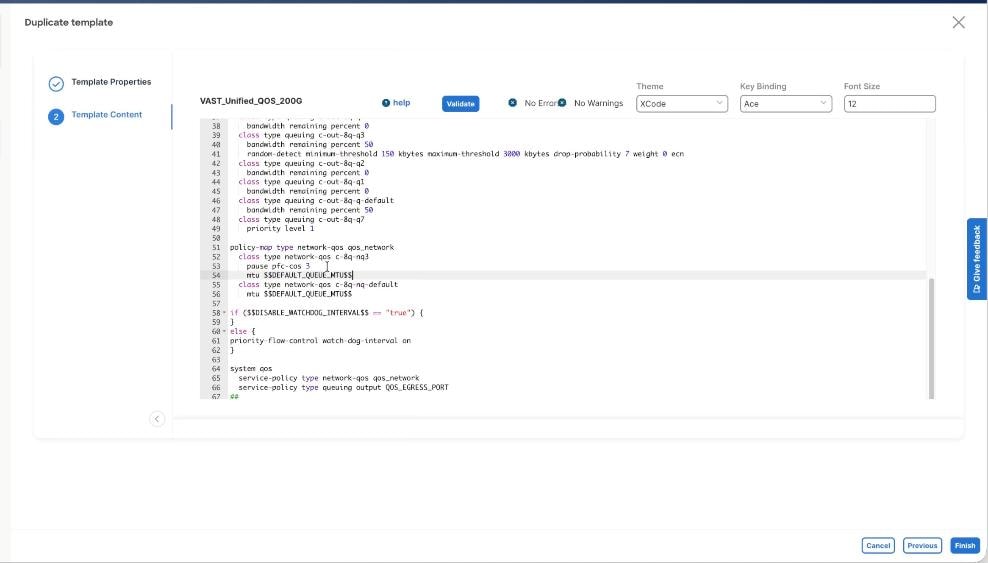
Step 8. In the Template Content section, modify the network-qos class c-8q-nq3 to $DEFAULT_QUEUE_MTU which is 9216. Click Finish.
Step 9. Go to Manage > Fabrics. Select the FE fabric from the list and click the FE fabric name.
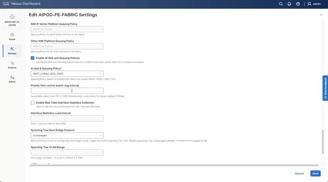
Step 10. Go to Actions > Edit Fabric Settings from the drop-down list. Select the Fabric Management tab and click the Advanced tab. Scroll through the Edit AIPOD-FE-Fabric Settings and check the Enable AI QOS and Queuing Policies option. From the AI QOS and Queuing Policies drop-down list, select the VAST_Unified_QOS_200G policy created in the previous steps. Click Save.
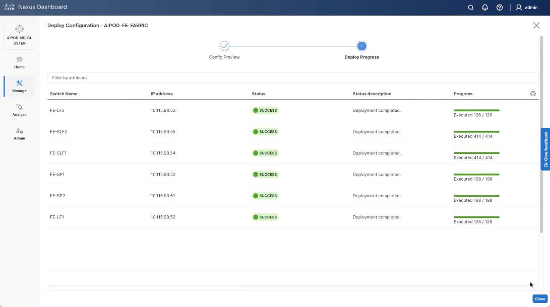
Step 11. From the AIPOD-FE-Fabric, click the Actions tab and select Recalculate and Deploy.
Step 12. Click Deploy All.
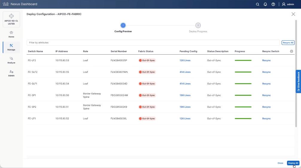
Step 13. Confirm the successful deployment to FE Fabric.
Enable Layer 2 Connectivity to Management UCS X-Direct from FE fabric
Table 10. Setup Parameters for FE Fabric: Layer 2 Connectivity to Management UCS X–Direct
| Leaf Switches |
FE-LF1, FE-LF2 |
|
| Management UCS |
UCS X-Direct with (-A, -B) uplinks; Both uplinks are dual-homed to FE-LF1 & FE-LF2 |
With multiple servers |
| Virtual Port Channel (vPC) |
To UCS X-Direct |
Management UCS-X Direct Chassis |
| vPC/PC1 - ID |
15 |
To UCS X-Direct: Side-A |
| vPC Pair |
FE-LF1, FE-LF2 |
|
| Ports |
1/5, 1/7 |
FI-A: Ports 1/1-4 (PC-11) |
| vPC/PC2 – ID |
16 |
To UCS X-Direct: Side-B |
| Ports |
1/6, 1/8 |
FI-B: Ports 1/1-4 (PC-12) |
To enable Layer 2 connectivity to the management of the Cisco UCS X-Series Direct chassis from the FE fabric, follow the procedures below. You will be configuring two vPCs to the management UCS X-Series Direct, one for -A side and another for -B side. Each vPC will use multiple ports on each compute leaf switch pair to connect to -A and -B uplinks on UCS X-Series Direct chassis.
Procedure 1. Deploy first vPC to Management UCS X-Series Direct
Step 1. From a web browser go to Nexus Dashboard. Use the management IP of any node in the ND cluster. Log in using admin account.
Step 2. From the left navigation menu, go to Manage > Fabrics.
Step 3. Select the FE fabric and go to Connectivity > Interfaces tab.
Step 4. Click the lower Actions button and select Create interface.
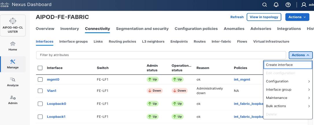
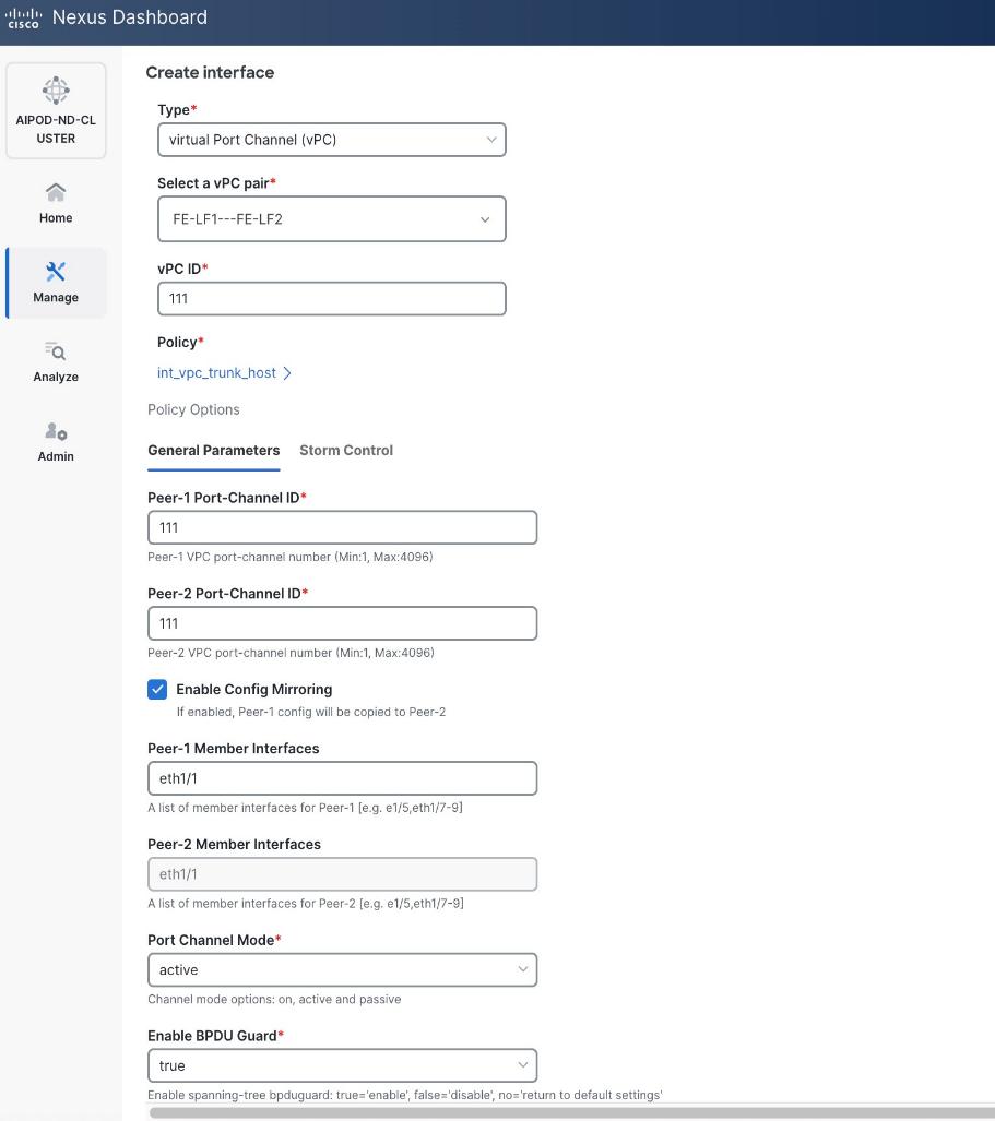
Step 5. In the Create interface window:
● Specify the Type of interface as virtual Port Channel (vPC) from the drop-down list.
● For the Select a vPC pair, select the compute leaf switch vPC pair from the drop-down list.
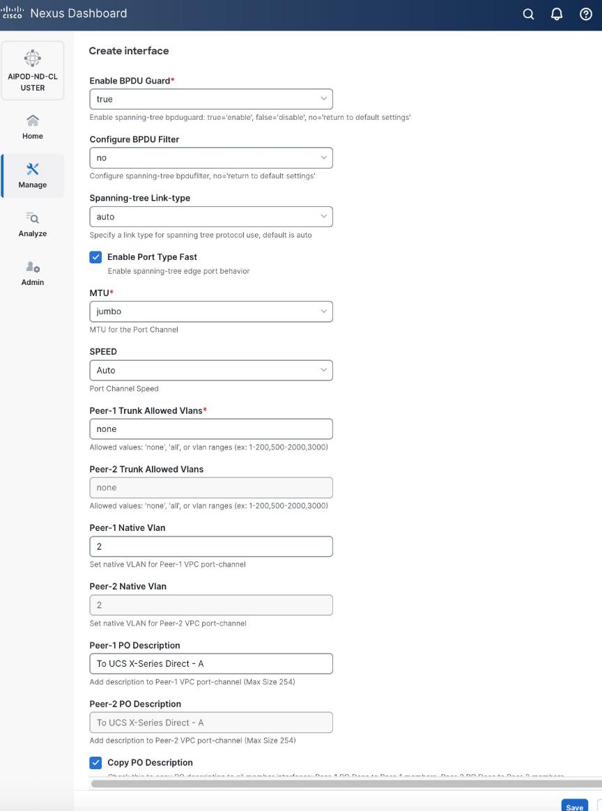
● Specify a vPC ID for the first vPC to the UCS X-Direct (-A side). Port Channel IDs from each switch to the first UCS node should match the vPC ID (see screenshot below).
● Leave the Policy as int_vpc_trunk_host.
● Enable checkbox for Config Mirroring to configure both vPC peer switches identically.
● Specify Peer-1 Member Interfaces that connects to first UCS node.
● Leave other fields as-is.
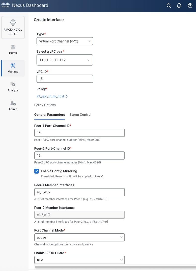
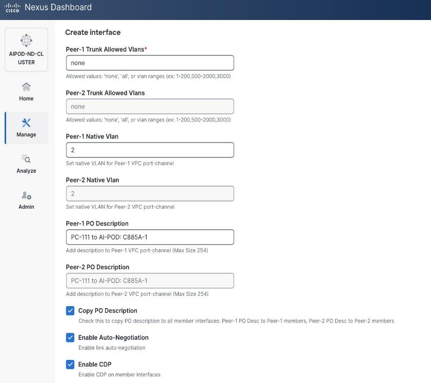
● Scroll down and fill remaining fields: Native VLAN, Peer-1 PO Description, and select the checkbox for Copy PO Description to copy the description to second vPC peer’s Port Channel.
Step 6. Click Save.
Step 7. Click Preview.
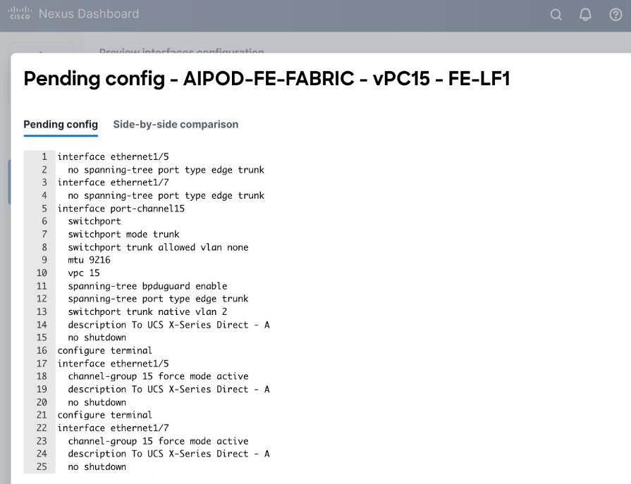
Step 8. Click Close, then click Cancel.
Step 9. Click Deploy. The Pending Config is the configuration shown in the previous step.
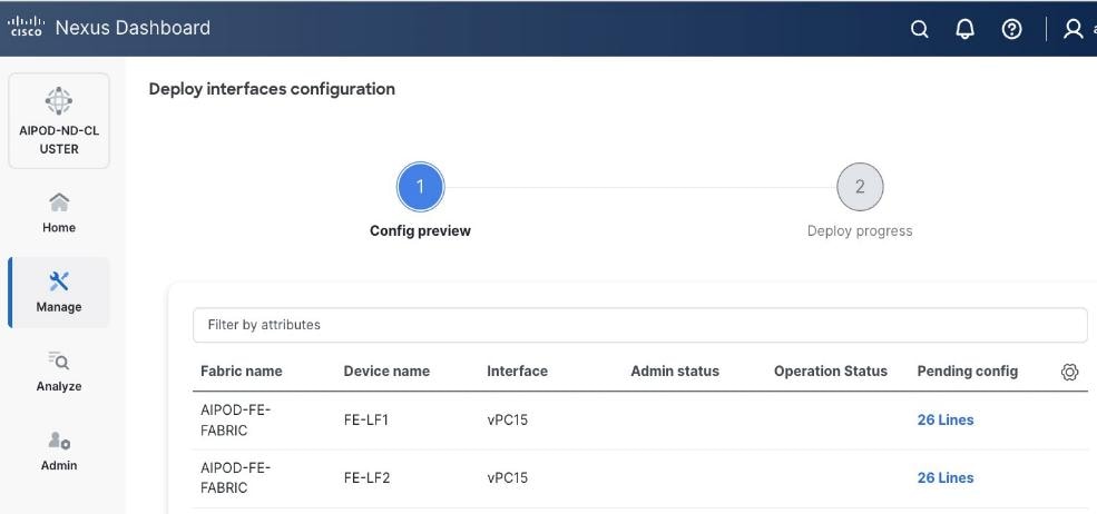
Step 10. Click Deploy Config.
Step 11. Verify that all the interfaces and port-channels are up on each switch in the vPC leaf pair that connects to the UCS X-Series Direct (-A side). It may take a few minutes for the vPC to go from Not discovered to consistent state.
Step 12. Repeat this procedure for the second vPC to UCS X-Series Direct (-B side).
Enable Layer 2 Connectivity to UCS GPU Nodes from FE Fabric
To enable layer 2 connectivity to UCS GPU nodes, you will be configuring four vPCs, one per Cisco UCS C885A node. Each vPC will use one port on each switch in the compute leaf pair to connect to the UCS node.
Note: The VAST NFS client, which builds on the standard Linux kernel NFS driver, has the option of local ports, which specifies multiple client-side IPs for outgoing traffic (NFSv3 only). If you use this options, vPC on GPU nodes is not required.
Table 11. Setup Parameters for FE Fabric: Layer 2 Connectivity to UCS GPU Nodes
| Leaf Switches |
FE-LF1, FE-LF2 |
|
| UCS Nodes |
4 x UCS C885A GPU Nodes, each dual-homed to FE-LF1 & FE-LF2 |
|
| Virtual Port Channel (vPC) |
To UCS C885As |
UCS GPU Nodes |
| vPC/PC1 - ID |
111 |
|
| vPC Pair |
FE-LF1, FE-LF2 |
|
| Ports |
1/1 |
On each Leaf switch |
| vPC/PC2 – ID |
112 |
|
| vPC Pair |
FE-LF1, FE-LF2 |
|
| Ports |
1/2 |
On each Leaf switch |
| vPC/PC3 - ID |
113 |
|
| vPC Pair |
FE-LF1, FE-LF2 |
|
| Ports |
1/3 |
On each Leaf switch |
| vPC/PC4 – ID |
114 |
|
| vPC Pair |
FE-LF1, FE-LF2 |
|
| Ports |
1/4 |
On each Leaf switch |
To enable Layer 2 connectivity to UCS C885A GPU nodes from the FE fabric, follow the procedures below.
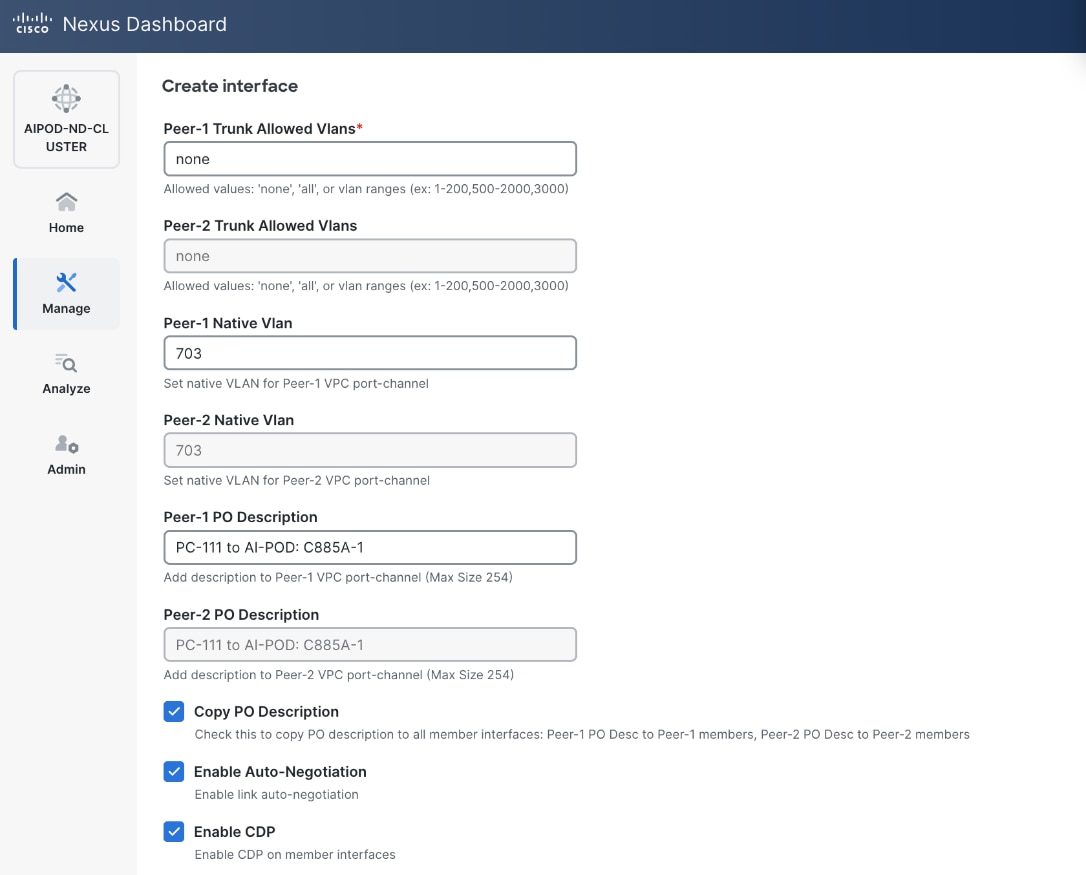
Procedure 1. Deploy first vPC to first UCS C885A GPU node
Step 1. From a web browser go to Nexus Dashboard. Use the management IP of any node in the ND cluster. Log in using admin account.
Step 2. From the navigation menu, go to Manage > Fabrics.
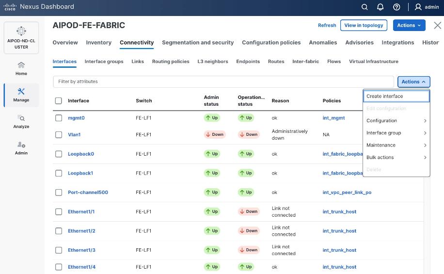
Step 3. Select the FE fabric and go to Connectivity > Interfaces tab.
Step 4. Click the lower of Actions button and select Create interface.
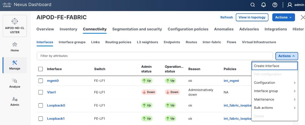
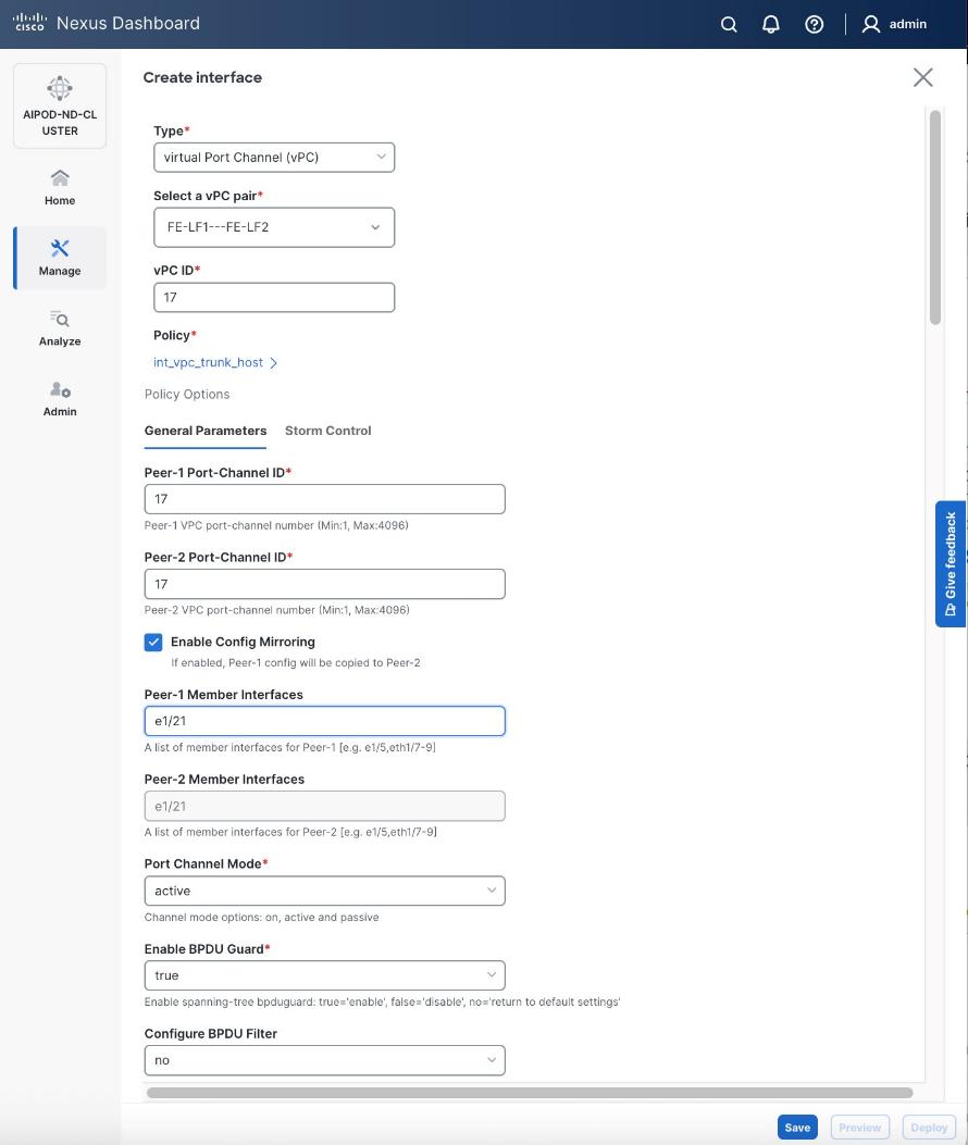
Step 5. In the Create interface window:
● Specify the Type of interface as virtual Port Channel (vPC) from the drop-down list.
● For the Select a vPC pair, select the compute leaf switch VPC pair from the drop-down list.
● Specify a vPC ID for the vPC to the first UCS GPU node. Peer-1 and Peer-2 Port-Channel ID should match that of the vPC ID.
● Leave the Policy as int_vpc_trunk_host.
● Enable checkbox for Config Mirroring.
● Specify Peer-1 Member Interfaces that connects to first UCS node.
● Specify Peer-1 Native VLAN.
● Specify Peer-1 PO Description.
● Select the checkbox for Copy PO Description to copy PO description to all member interfaces.
Step 6. Additional configuration changes can be made later as needed. Click Save.
Step 7. Click Preview to view the Pending config changes.
Step 8. Click Pending Config for each switch to see the configuration.
Step 9. Click the X in the top right corner and select Deploy and Deploy config to deploy the Pending config changes.
Step 10. Click Close when deployment completes successfully.
Step 11. Verify that all the interfaces and port-channel is up on each switch in the leaf switch pair that connects to the UCS node. It may take a few minutes for the vPC to go from Not discovered to consistent state.
Step 12. Repeat this procedure to provision layer 2 connectivity from the compute/management leaf switches to the remaining 3 UCS nodes in the cluster.
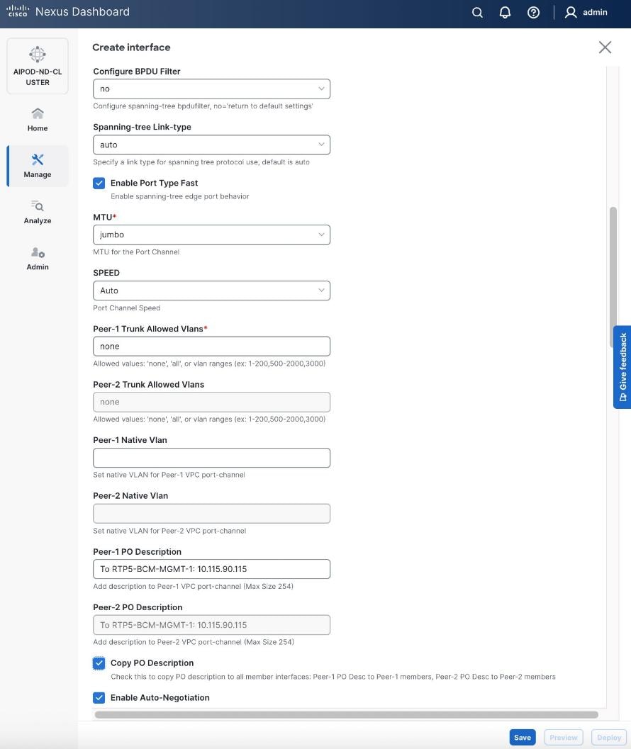
(Ubuntu) Enable Layer 2 Connectivity to NVIDIA BCM Nodes
If running Ubuntu on the Cisco UCS C885A M8 nodes under NVIDIA BCM, to enable Layer 2 connectivity to the BCM (UCS) node(s) from the FE fabric, you will be configuring two vPCs from the same BCM node: one to compute/management leaf pair and another storage leaf pair.
Table 12. Setup Parameters for FE Fabric: Layer 2 Connectivity to NVIDIA BCME Nodes
| Virtual Port Channel (vPC) |
To BCME Node |
Management/Control/Workload Management Node |
| vPC/PC1 - ID |
17 |
|
| vPC Pair |
FE-LF1, FE-LF2 |
|
| Ports |
1/21 |
|
| vPC/PC1 - ID |
18 |
|
| vPC Pair |
FE-SLF1, FE-SLF2 |
|
| Ports |
1/24 |
|
To enable Layer 2 connectivity to the BCM (UCS) node(s) from the FE fabric, follow the procedures below.
Procedure 1. Deploy first vPC to BCM node from compute leaf switch pair
Step 1. From a web browser go to Nexus Dashboard. Use the management IP of any node in the ND cluster. Log in using admin account.
Step 2. From the navigation menu, go to Manage > Fabrics.
Step 3. Select the FE fabric and go to Connectivity > Interfaces tab.
Step 4. Click the lower Actions button and select Create interface.
Step 5. In the Create interface window:
● Specify the Type of interface as virtual Port Channel (vPC) from the drop-down list.
● For the Select a vPC pair, select the leaf switch pair from the drop-down list.
● Specify a vPC ID for the first vPC to the BCME node. Port Channel IDs from each switch to the first UCS node should match the vPC ID (see screenshot below).
● Leave the Policy as int_vpc_trunk_host.
● Enable checkbox for Config Mirroring to configure both vPC peer switches identically.
● Specify Peer-1 Member Interfaces that connects to the BCME node.
Step 6. Scroll down and fill remaining fields: Native VLAN (optional), Peer-1 PO Description, Copy PO Description.
Step 7. Click Save.
Step 8. Click Preview.
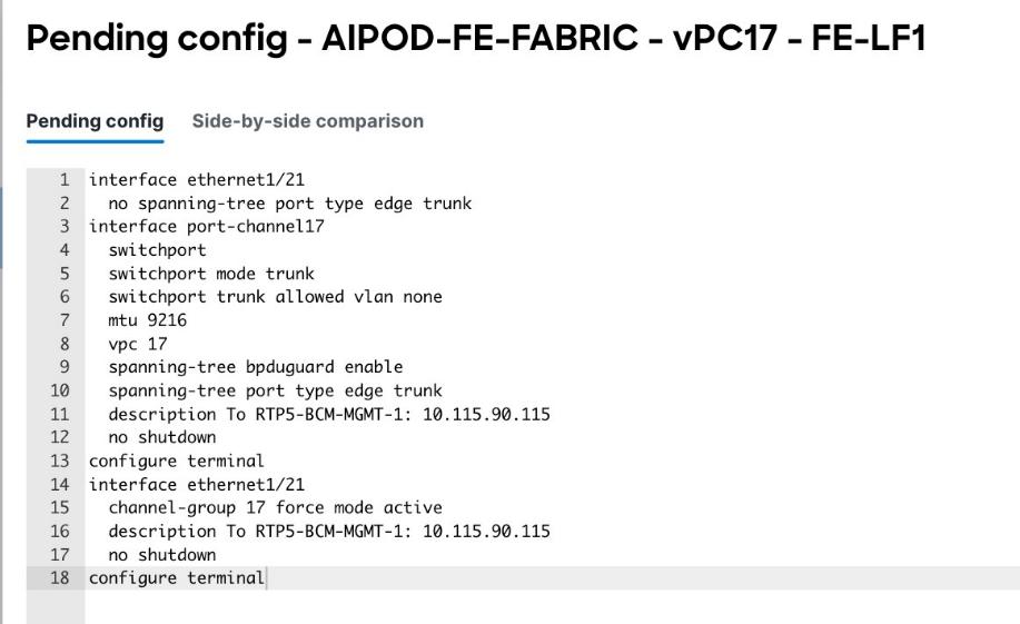
Step 9. Click Close, the click Cancel.
Step 10. Click Deploy. The Pending Config is the configuration shown in the previous step.
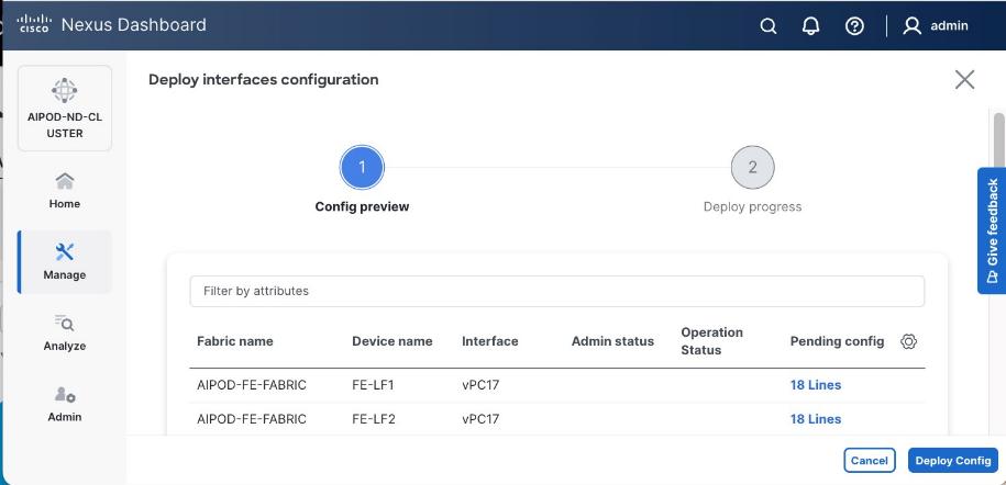
Step 11. Click Deploy Config.
Step 12. Verify that all the interfaces and port-channels are up on each switch in the vPC leaf pair that connects to the BCME node. It may take a few minutes for the vPC to go from Not discovered to consistent state.
Step 13. Repeat this procedure for the second vPC from storage leaf pair to BCME node.
(Ubuntu) Enable Layer 2 Connectivity to UCS GPU Nodes from FE Fabric
If running Ubuntu on the Cisco UCS C885A M8 nodes under NVIDIA BCM, to enable Layer 2 connectivity to UCS C885A GPU nodes from the FE fabric, you will be configuring four vPCs, one per Cisco UCS C885A node. Each vPC will use one port on each switch in the compute leaf pair to connect to the UCS node.
Table 13. Setup Parameters for FE Fabric: Layer 2 Connectivity to UCS GPU Nodes
| Leaf Switches |
FE-LF1, FE-LF2 |
|
| UCS Nodes |
4 x UCS C885A GPU Nodes |
Each node is dual-homed to FE-LF1 & FE-LF2 |
| Virtual Port Channel (vPC) |
To UCS C885As |
UCS GPU Nodes |
| vPC/PC1 - ID |
111 |
To UCS C885A-1 |
| vPC Pair |
FE-LF1, FE-LF2 |
|
| Ports |
1/1 |
On each Leaf switch |
| vPC/PC2 – ID |
112 |
To UCS C885A-2 |
| vPC Pair |
FE-LF1, FE-LF2 |
|
| Ports |
1/2 |
On each Leaf switch |
| vPC/PC3 - ID |
113 |
To UCS C885A-3 |
| vPC Pair |
FE-LF1, FE-LF2 |
|
| Ports |
1/3 |
On each Leaf switch |
| vPC/PC4 – ID |
114 |
To UCS C885A-4 |
| vPC Pair |
FE-LF1, FE-LF2 |
|
| Ports |
1/4 |
On each Leaf switch |
To enable Layer 2 connectivity to UCS C885A GPU nodes from the FE fabric, follow the procedures below. You will be configuring four vPCs, one per Cisco UCS C885A node. Each vPC will use one port on each switch in the compute leaf pair to connect to the UCS node.
Procedure 1. Deploy first vPC to first UCS C885A GPU node
Step 1. From a web browser go to Nexus Dashboard. Use the management IP of any node in the ND cluster. Log in using admin account.
Step 2. From the left navigation menu, go to Manage > Fabrics.
Step 3. Select the FE fabric and go to Connectivity > Interfaces tab.
Step 4. Click the lower Actions button and select Create interface.
Step 5. In the Create interface window:
● Specify the Type of interface as virtual Port Channel (vPC) from the drop-down list.
● For the Select a vPC pair, select the compute leaf switch VPC pair from the drop-down list.
● Specify a vPC ID for the vPC to the first UCS GPU node. Peer-1 and Peer-2 Port-Channel ID should match that of the vPC ID.
● Leave the Policy as int_vpc_trunk_host.
● Enable checkbox for Config Mirroring.
● Specify Peer-1 Member Interfaces that connects to first UCS node.
● Specify Peer-1 Native VLAN.
● Specify Peer-1 PO Description.
● Enable checkbox for Copy PO Description to copy PO description to all member interfaces.
● Select the checkbox for Disable LACP Suspend-individual .
● Leave everything else as is. Additional configuration changes can be made later as needed.

Step 6. Click Save.
Step 7. Click Preview.
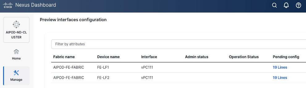
Step 8. To view the Pending config changes, click the Pending Config column for each switch (X lines) to see the configuration. The configuration is provided as a reference from one leaf switch.
Step 9. Click the X in the top right corner and select Deploy and Deploy config to deploy the Pending config changes.
Step 10. Click Close when deployment completes successfully.
Step 11. Verify that all the interfaces and port-channel is up on each switch in the leaf switch pair that connects to the UCS node. It may take a few minutes for the vPC to go from Not discovered to consistent state.
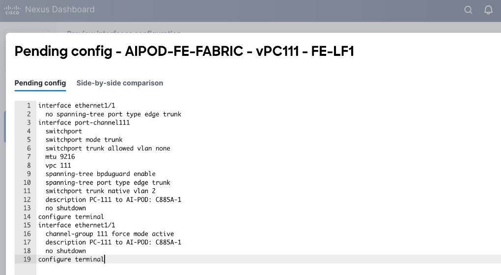
The deployed configuration on one leaf switch is provided as a reference below:
Step 12. Repeat this procedure to provision layer 2 connectivity from the compute/management leaf switches to the remaining 3 UCS nodes in the cluster.
Enable In-Band Management Connectivity to UCS GPU and Management Nodes
The In-band management (IB-MGMT) network in the FE fabric will provide the following connectivity:
● Connectivity from control, management and services nodes to the UCS GPU nodes where the AI workload is running.
● Connectivity to other networks (networks outside this FE fabric to other networks within the enterprise or external to the enterprise).
Table 14. Setup Parameters for FE Fabric: In-Band Management Connectivity to UCS Management and GPU Nodes
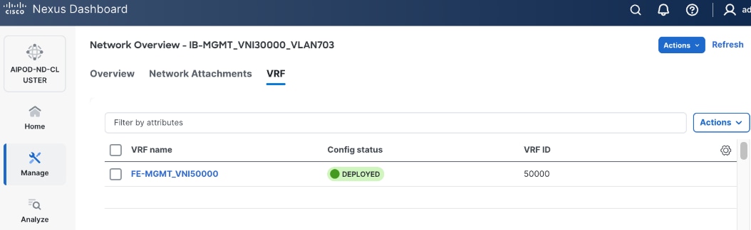
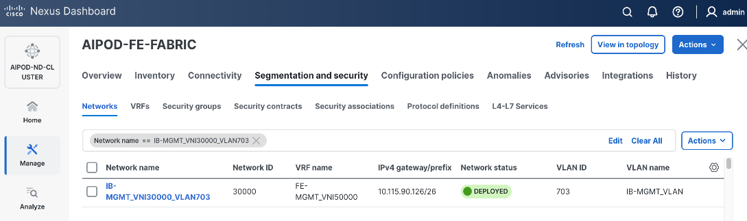
| IB-MGMT Network |
|
|
| Name |
IB-MGMT_VN30000_VLAN703 |
|
| Layer 2 Only |
No |
|
| IB-MGMT VRF |
|
|
| VRF Name |
FE-MGMT_VN50000 |
|
| VRF ID |
50000 |
(System Proposed) |
| VLAN ID |
2000 |
(System Proposed) |
| VRF Interface Description |
FE-MGMT VRF |
|
| VRF Description |
Frontend Fabric – Management VRF |
|
| IB-MGMT Network Contd. |
|
|
| Network ID |
30000 |
|
| VLAN ID |
703 |
|
| IPv4 Gateway/Netmask |
10.115.90.126/26 |
|
| VLAN Name |
IB-MGMT_VLAN |
|
| Interface Description |
IB-MGMT |
|
| UCS C885A GPU Nodes |
|
|
| vPC Leaf Switch Pair |
FE-LF1, FE-LF2 |
vPC Leaf Switch Pair |
| UCS C885-A Node-1 Interface |
Port-Channel 111 |
|
| UCS C885-A Node-2 Interface |
Port-Channel 112 |
|
| UCS C885-A Node-3 Interface |
Port-Channel 113 |
|
| UCS C885-A Node-4 Interface |
Port-Channel 114 |
|
| Management UCS X-Direct Chassis |
|
|
| vPC Leaf Switch Pair |
FE-LF1, FE-LF2 |
|
| UCS X-Direct (-A Uplinks) |
Port-Channel 15 |
|
| UCS X-Direct (-B Uplinks) |
Port-Channel 16 |
|
To deploy the in-band management network and enable connectivity to the UCS GPU nodes, follow the procedures below.
Procedure 1. Deploy In-Band Management Connectivity for UCS GPU Nodes
Step 1. From a web browser go to Nexus Dashboard. Use the management IP of any node in the ND cluster. Log in using admin account.
Step 2. From the navigation menu, go to Manage > Fabrics.
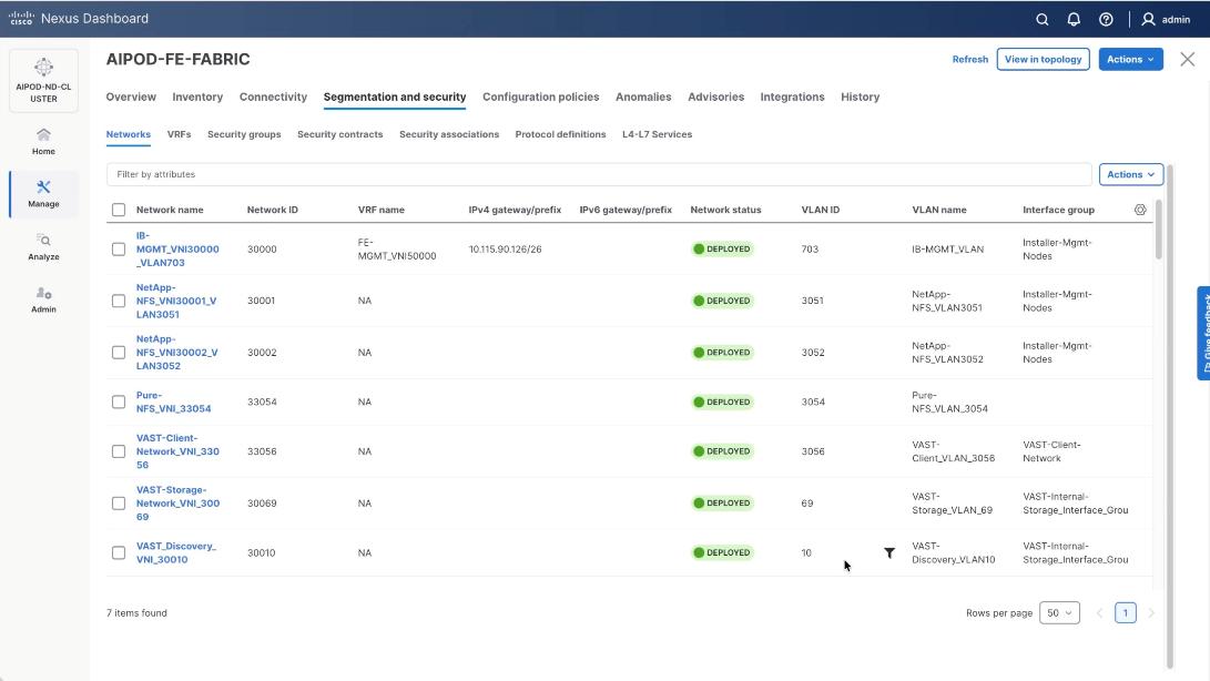
Step 3. Select the FE fabric and go to Segmentation and Security > Networks tab.
Step 4. Click the lower Actions button and select Create from the list.
Step 5. In the Create Network window, specify the following:
● Network name for the IB-MGMT network.
● Leave unchecked the Layer 2 only checkbox as IB-MGMT is a layer 3 overlay network.
● VRF name. If a VRF hasn't been created already, you have an option from this window to also create a VRF.
● To create a new VRF, click on Create VRF. In the Create VRF window, specify VRF ID (or use default), VLAN ID (or click the Propose VLAN button to let system define a VLAN), and optionally other parameters as shown in the following screenshot.
Step 6. Click Create to create the VRF and return to the Create Network window.
Step 7. In the Create Network window, specify the following:
● Network ID or use default.
● VLAN ID or click Propose VLAN to let system define a VLAN.
● In the General Parameters tab, specify IP Gateway/Netmask, VLAN Name and Interface Description.
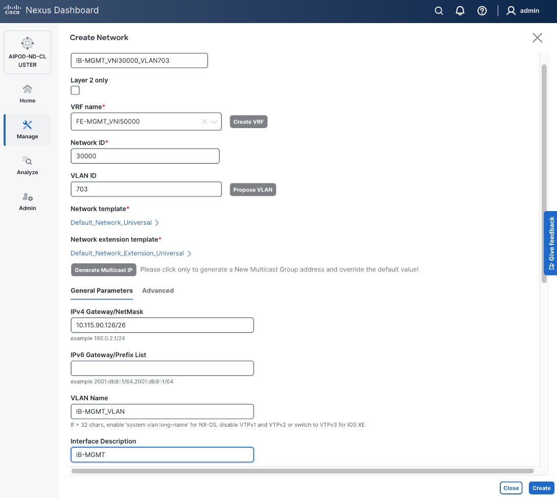
Step 8. Click Create to create the Network.
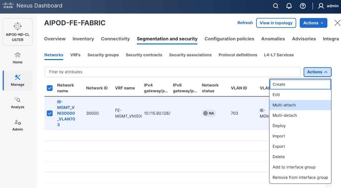
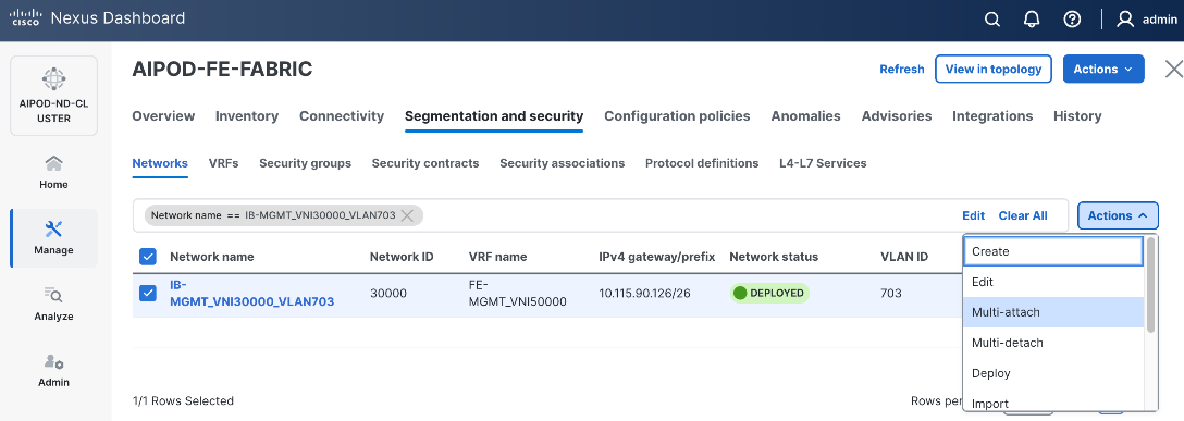
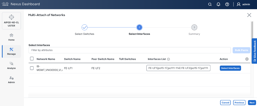
Step 9. Select newly created network and deploy it on both leaf pairs. Click the lower Actions button and select Multi-attach from the list.
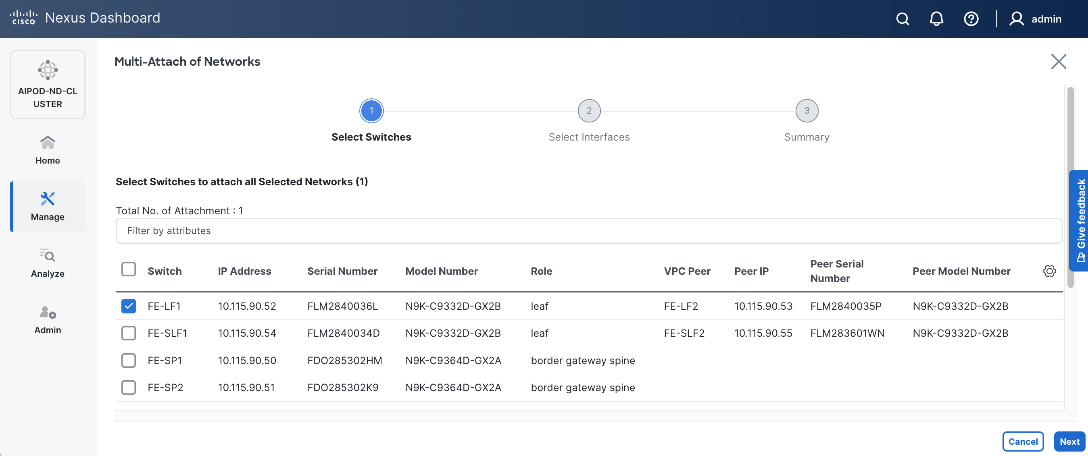
Step 10. Select the Leaf switch pairs. Enabling this network on storage leaf pairs as shown below may not be necessary in all deployments.
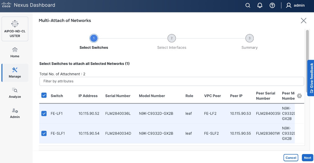
Step 11. Click Next.
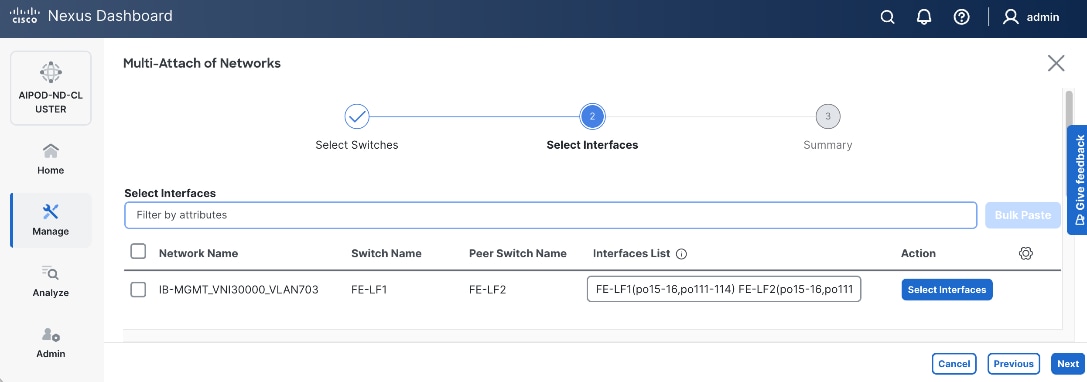
Step 12. Select each switch pair in the list and click Select interfaces to deploy this network as a trunked VLAN (VLAN 703) on the selected interfaces. Select the interfaces on the compute leaf switches that connect to the UCS GPU nodes. Additional interfaces can be added later as needed.
Step 13. Click Next.
Step 14. Click Save.
Step 15. Click Pending Config to see the configuration being deployed. The pending configuration on one leaf switch is provided as a reference at the end.
Step 16. Click Deploy All.
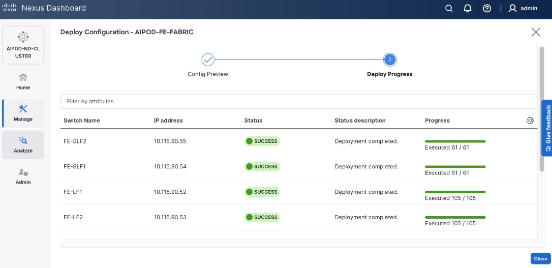
Step 17. Click Close.
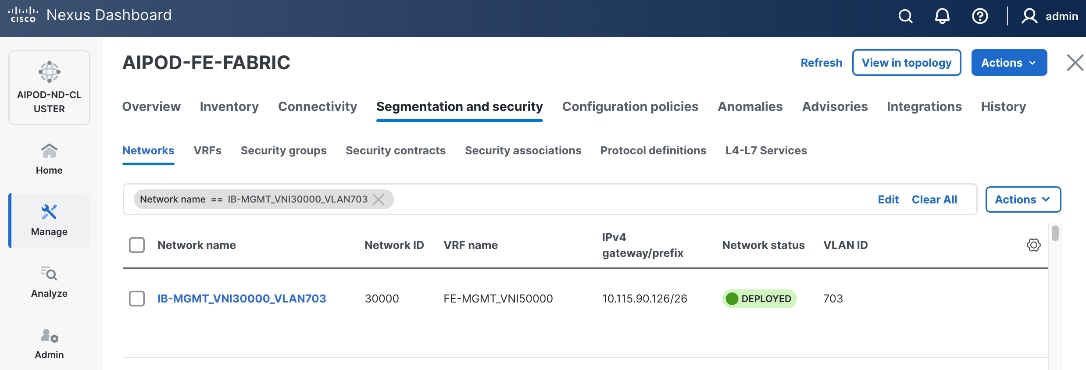
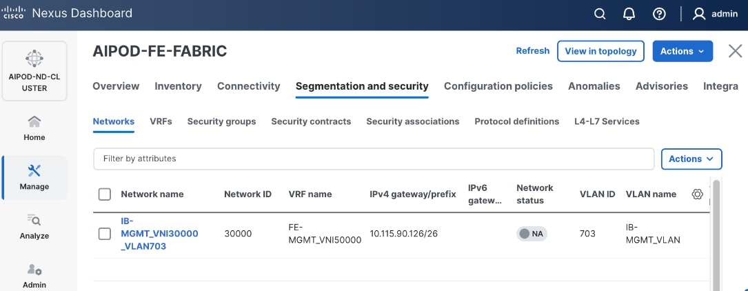
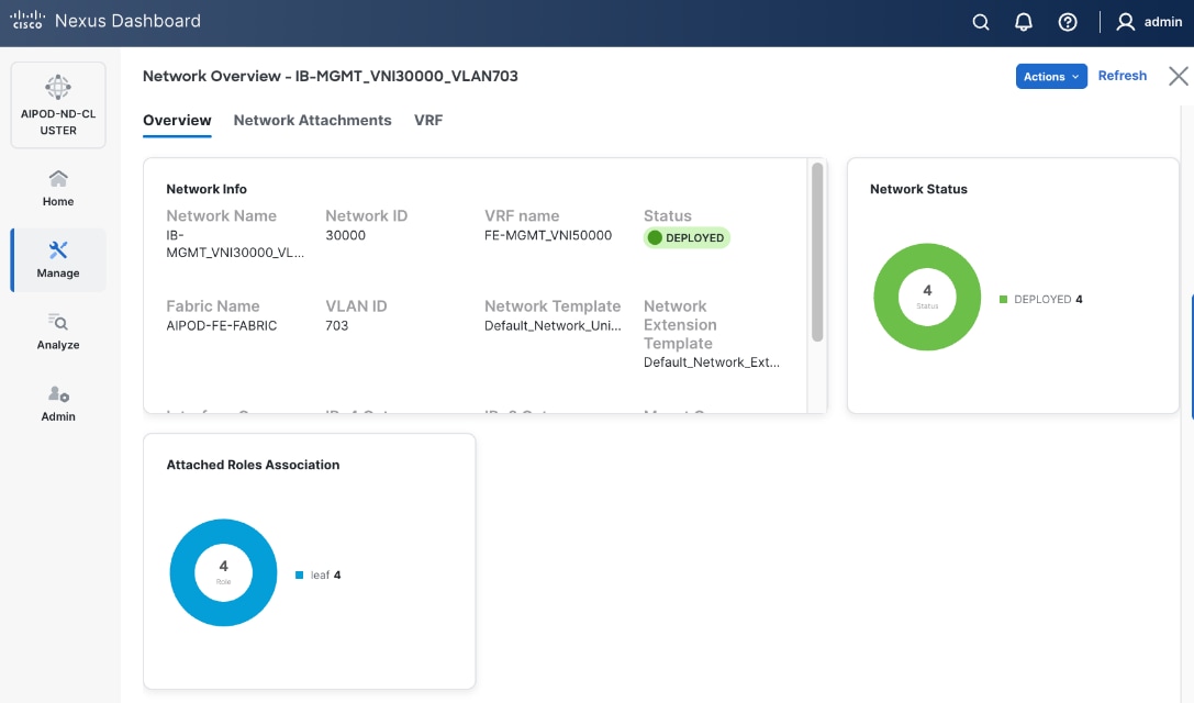
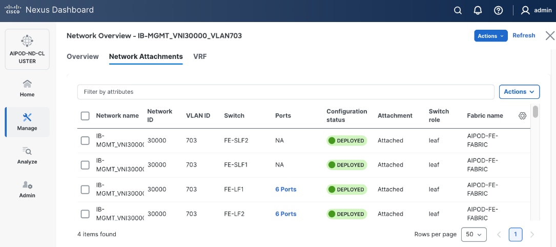
Step 18. Click the Network name to verify that the network was successfully deployed on the relevant switches and interfaces.
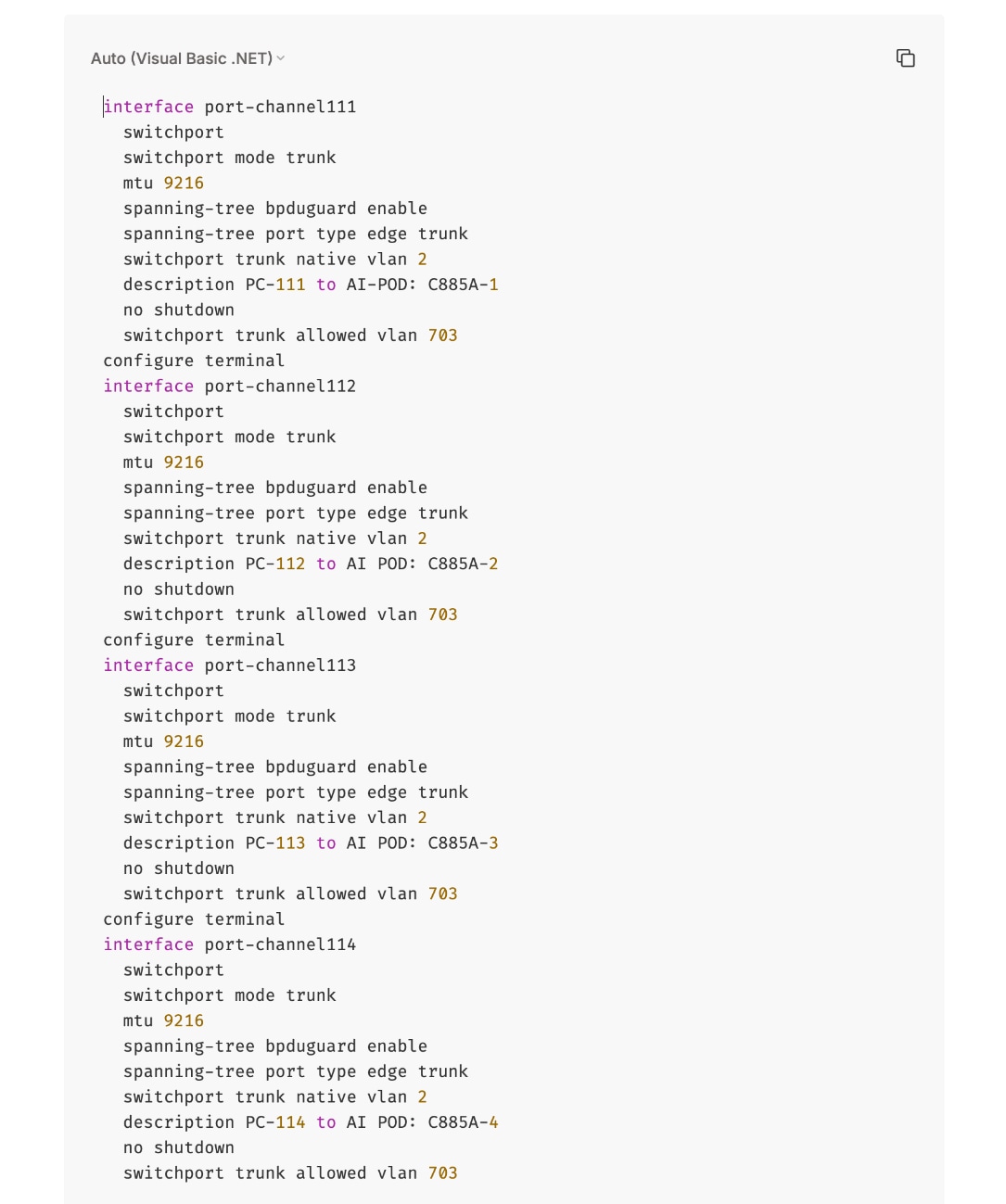
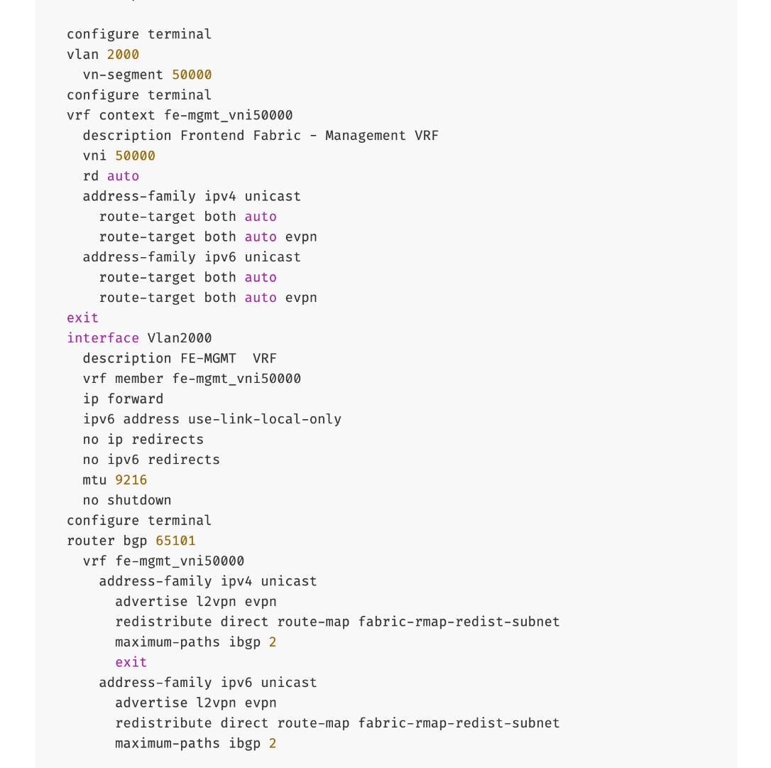
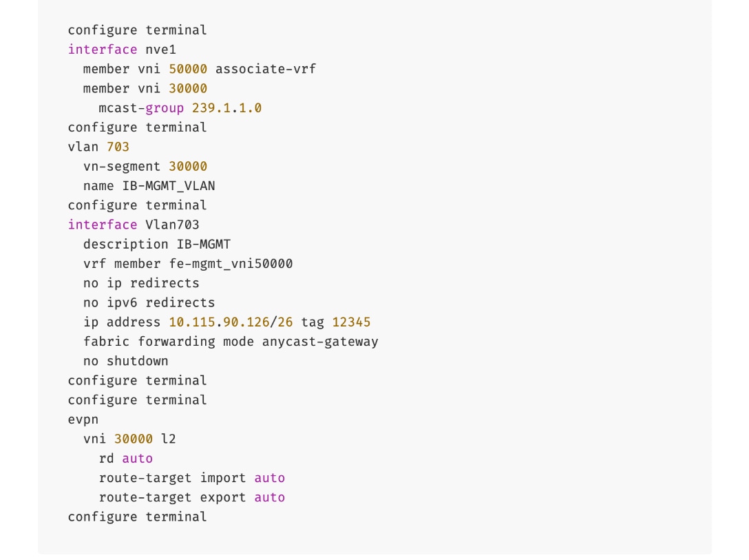
The configuration deployed on one compute leaf switch is provided below:
To deploy in-band management connectivity to Management UCS X-Series Direct on the compute leaf switches in the FE fabric, follow the procedures below.
Procedure 2. Deploy in-band management connectivity for management UCS X-Direct chassis
Step 1. From a web browser go to Nexus Dashboard. Use the management IP of any node in the ND cluster. Log in using admin account.
Step 2. From the navigation menu, go to Manage > Fabrics.
Step 3. Select the FE fabric and go to Segmentation and Security > Networks tab.
Step 4. Select the previously deployed in-band management network from the list.
Step 5. Click the lower Actions button and select Multi-attach from the list.
Step 6. Select the leaf switch pair from the list which the UCS X-Series Direct system connects.
Step 7. Click Next.
Step 8. Click Select Interfaces to the right of the leaf switch pair to add the interfaces that connect to management UCS X-Series Direct.
Step 9. Click Next.
Step 10. Click Save.
Step 11. Click Deploy All.
Step 12. Click Close.
Step 13. Click the Network name to verify that the network was successfully deployed on the relevant switches and interfaces.
The configuration deployed on one compute leaf switch is provided below as a reference:
(Ubuntu) Enable In-Band Management Connectivity to BCM Node(s)
To deploy in-band management connectivity to BCM node connected to compute leaf switches in the FE fabric, you will be deploying this network on the compute Leaf switch pair that connects to the BCM node.
Table 15. Setup Parameters for FE Fabric: In-Band Management Connectivity to BCME Nodes
| Parameter Type |
Parameter Name | Value |
Parameter Type |
| IB-MGMT Network |
|
|
| Name |
IB-MGMT_VN30000_VLAN703 |
|
| IB-MGMT VRF |
|
|
| VRF Name |
FE-MGMT_VN50000 |
|
| Management BCME Node |
|
|
| vPC Leaf Switch Pair |
FE-LF1, FE-LF2 |
|
| BCM Interface |
Port-Channel 17 |
|
To deploy in-band management connectivity to BCM node connected to compute leaf switches in the FE fabric, follow the procedures below.
Procedure 1. Enable in-band management connectivity to BCM node
Step 1. From a web browser go to Nexus Dashboard. Use the management IP of any node in the ND cluster. Log in using admin account.
Step 2. From the navigation menu, go to Manage > Fabrics.
Step 3. Select the FE fabric and go to Segmentation and Security > Networks tab.
Step 4. Select the previously deployed in-band management network from the list.
Step 5. Click the lower Actions button and select Multi-attach from the list.
Step 6. Select the leaf switch pair from the list that the BCME node connects.
Step 7. Click Next.
Step 8. Click Select Interfaces to the right of the network name to add the interfaces that connect to the BCM node.
Step 9. Click Save.
Step 10. Click Next.
Step 11. Click Save.
The configuration deployed on one compute leaf switch is provided below as a reference:
Step 12. Click Deploy All.
Step 13. Click Close.
Step 14. Click the Network name to verify that the network was successfully deployed on the relevant switches and interfaces.
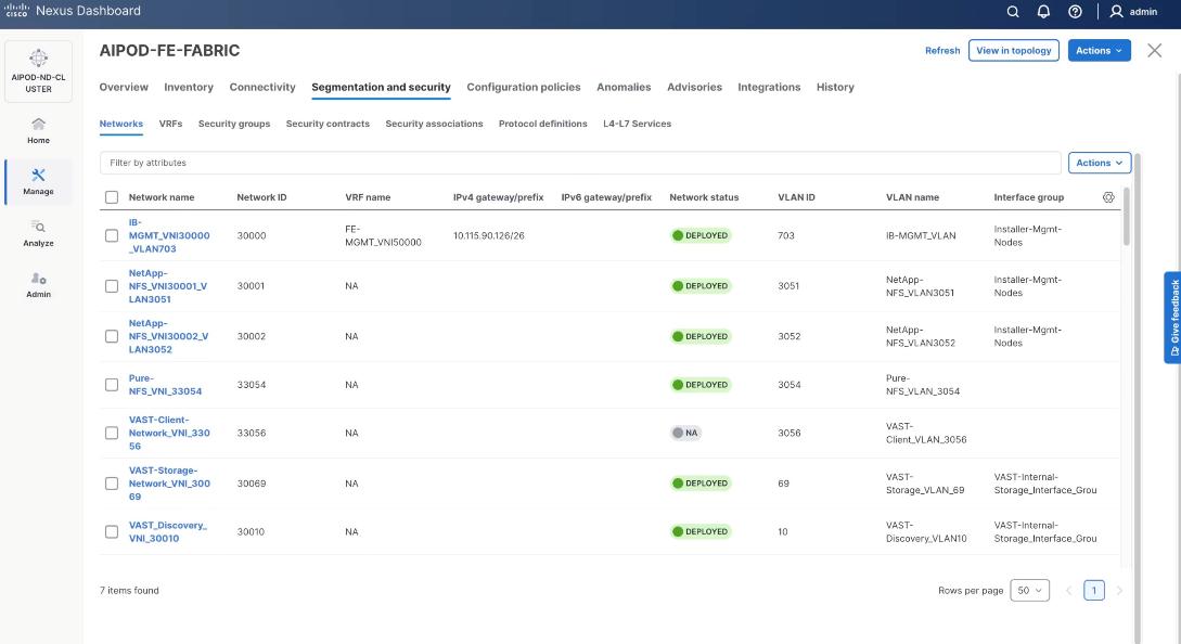
Enable Layer 2 Connectivity on FE Fabric for VAST Data on Cisco EBox
This section details configuring the Layer 2 connectivity from the FE fabric to VAST storage.
Table 16. Setup Parameters for FE Fabric: VAST Internal Storage Network and VAST External Network
| Parameter Type |
Parameter Name | Value |
| Name |
VAST-Storage-Network_VNI_30069 |
| Layer 2 Only |
Enable checkbox |
| Network ID |
30069 |
| VLAN ID |
69 |
| VLAN Name |
VAST-Storage_VLAN_69 |
| Interface Description |
VAST-Client-Network_VNI_30069, vast internal network traffic |
| Name |
VAST-Discovery_VNI_30010 |
| Layer 2 Only |
Enable checkbox |
| Network ID |
30010 |
| VLAN ID |
10 |
| VLAN Name |
VAST-Storage_VLAN_10 |
| Interface Description |
VAST-Discovery_VNI_30010, VAST cluster node discovery VLAN, native VLAN on vast storage port |
| VAST Client network |
VAST-Client-Network_VNI_33056 |
| Layer 2 Only |
Enable checkbox |
| Network ID |
33056 |
| VLAN ID |
3056 |
| VLAN Name |
VAST-Client_VLAN_3056 |
| Interface Description |
VAST-Storage-Network_VNI_33056 |
Table 17. FE Fabric ports for Layer 2 Connectivity to Cisco EBox nodes
| Parameter Type |
Parameter Name | Value |
Parameter Type |
| Leaf Switches |
FE-SLF1, FE-SLF2 |
|
| VAST Storage |
|
To Storage Leaf Switches |
| FE-SLF1 |
|
|
| VAST internal Storage network Ports |
1/9 to 1/14 |
Each 400GbE port is configured as 2x 200GbE breakout port |
| VAST External network Ports |
1/15 to 1/20 |
Each 400GbE port is configured as 2x 200GbE breakout port |
| FE-SLF2 |
|
|
| VAST internal storage Network Ports |
1/9 to 1/14 |
Each 400GbE port is configured as 2x 200GbE breakout port |
| VAST External network Ports |
1/15 to 1/20 |
Each 400GbE port is configured as 2x 200GbE breakout port |
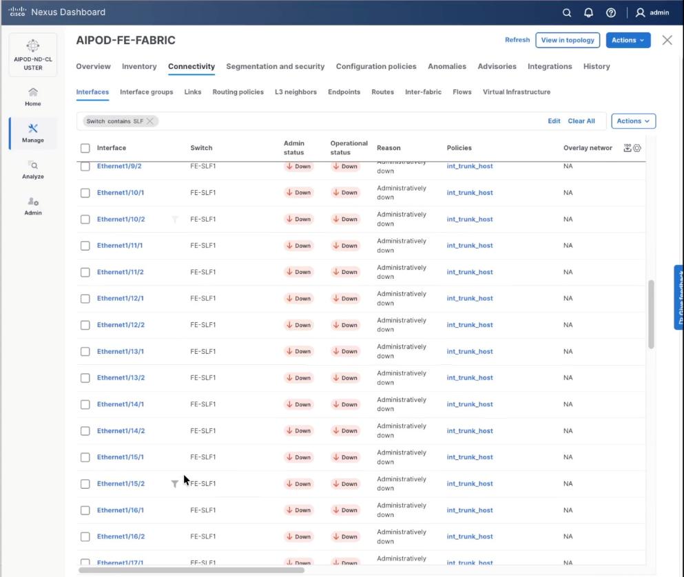
To enable Layer 2 connectivity from the FE fabric to VAST EBox nodes, follow the procedures below.
Procedure 1. Configure breakout ports on Storage leaf switches
Step 1. From a web browser go to the Nexus Dashboard. Use the management IP of any node in the ND cluster. Log in using admin account.
Step 2. From the navigation menu, go to Manage > Fabrics.
Step 3. Select the FE fabric and go to Connectivity > Interfaces tab.
Step 4. Select Filter on the storage leaf switches (SLF) and select the VAST internal storage ports that connect to VAST EBox nodes. From the Actions drop-down list, select Interface Group > Add.
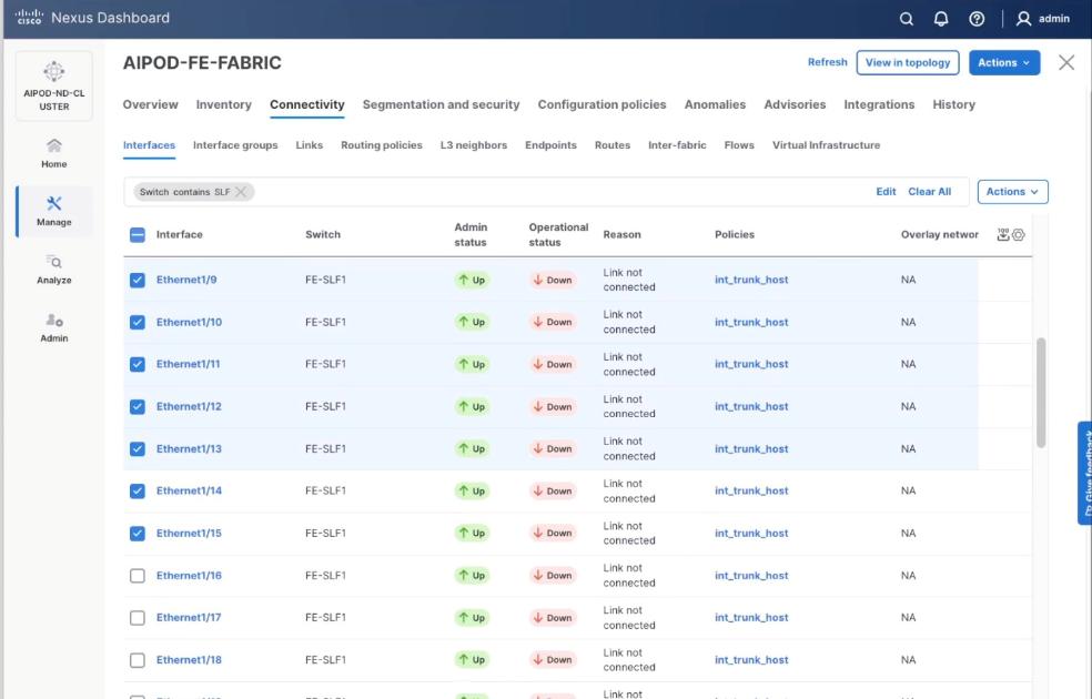
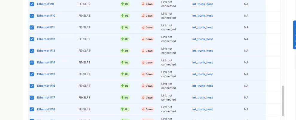
Step 5. Click Action and select Configuration > Breakout.
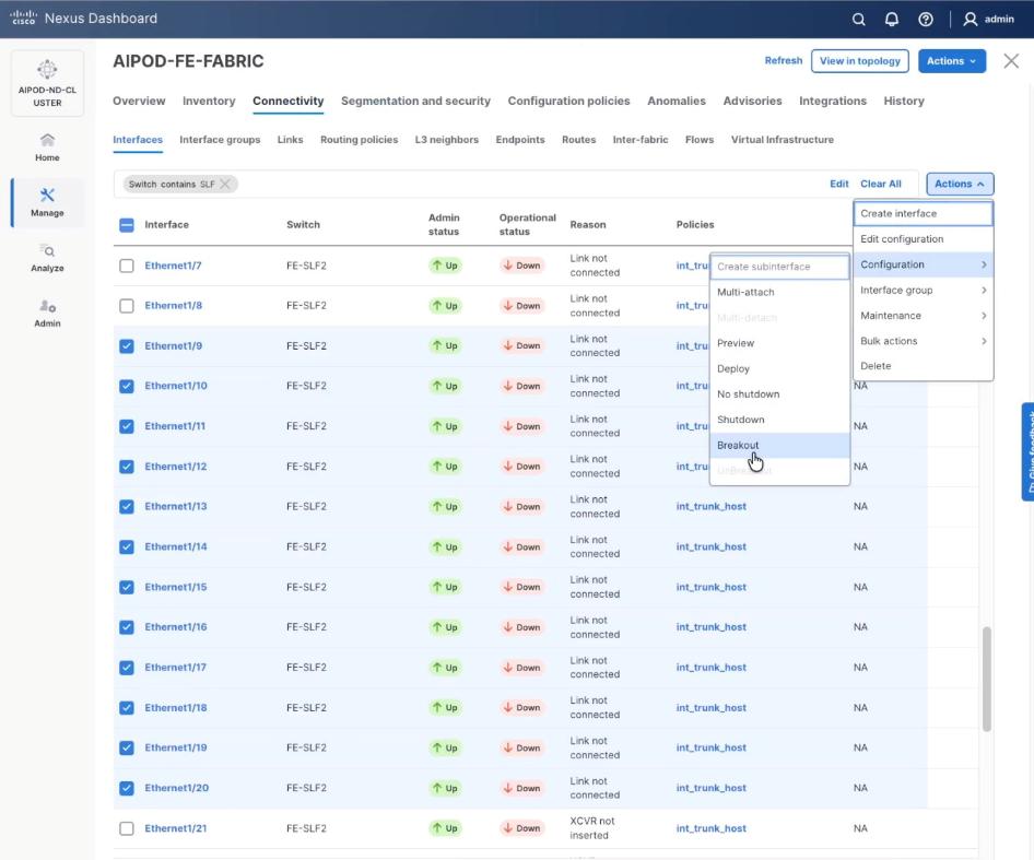
Step 6. Select 200g-2x and click Breakout.
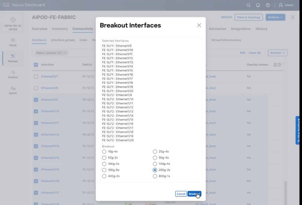
Step 7. Verify the 200G breakout ports are configured successfully.
Procedure 2. Create Networks for VAST Data
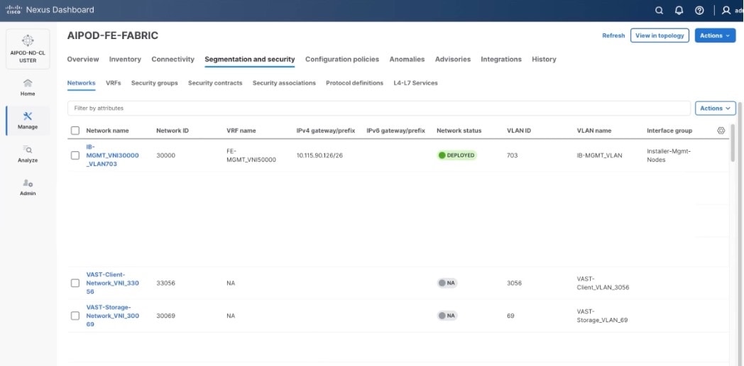
The section details the creation of network deployed for VAST Data. The three networks created are:
● VAST-Client-Network_VNI_30069
● VAST-Discovery_VNI_30010
● VAST-Client-Network_VNI_33056
Step 1. From a web browser go to the Nexus Dashboard. Use the management IP of any node in the ND cluster. Log in using admin account.
Step 2. From the navigation menu, go to Manage > Fabrics.
Step 3. Select the FE fabric and go to Segmentation and Security > Networks tab.
Step 4. Click the lower Actions button and select Create from the menu.
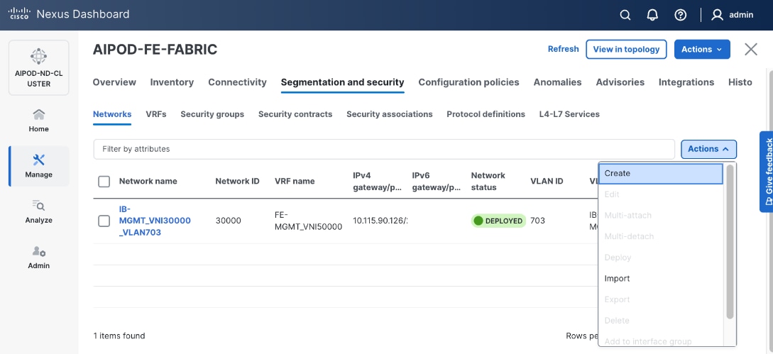
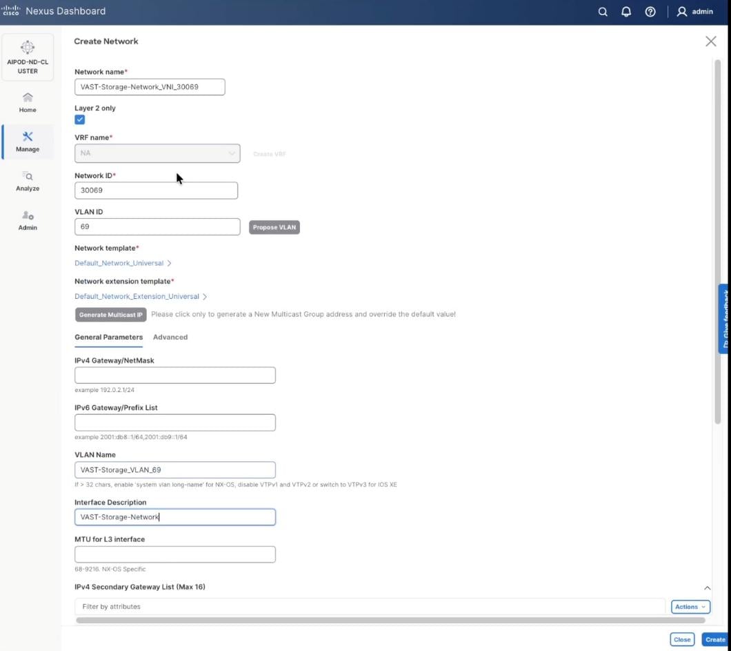
Step 5. In the Create Network window, specify the following:
● Network name: VAST-Storage-Network_VNI_30069
● Enable checkbox for Layer 2 only.
● Network ID or use 30069.
● VLAN ID 69.
● In the General Parameters tab, specify VLAN Name and Interface Description.
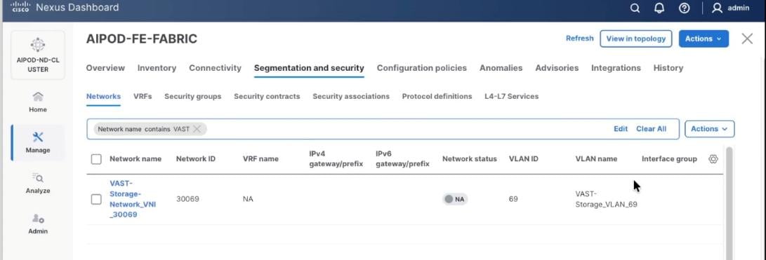
Step 6. Verify created network.
Step 7. Repeat steps 1 – 6 to create VAST Discovery network. From a web browser go to the Nexus Dashboard. Use the management IP of any node in the ND cluster. Log in using admin account.
Step 8. From the navigation menu, go to Manage > Fabrics.
Step 9. Select the FE fabric and go to Segmentation and Security > Networks tab.
Step 10. Click the lower Actions button and select Create from the menu.
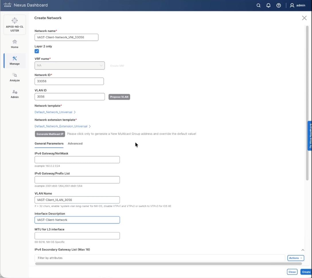
Step 11. In the Create Network window, specify the following:
● Network name: VAST-Discovery_VNI_30010
● Enable checkbox for Layer 2 only.
● Network ID or use 30010.
● VLAN ID 10.
● In the General Parameters tab, specify VLAN Name and Interface Description.
Step 12. Confirm creation of the network.
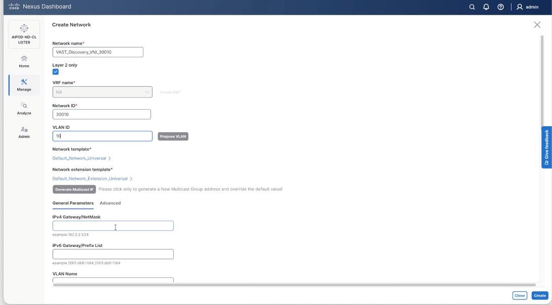
Step 13. Repeat steps 1 – 12 to create VAST Client network. Click the lower Actions button and select Create from the menu.
Step 14. In the Create Network window, specify the following:
● Network name: VAST-Client-Network_VNI_33056
● Enable checkbox for Layer 2 only
● Network ID or use 33056
● VLAN ID 3056
● In the General Parameters tab, specify VLAN Name and Interface Description
Step 15. Confirm creation of all three networks deployed in this solution.
Procedure 3. Deploy VAST Internal storage network
This procedure details the following:
● Configure VAST native Discovery VLAN for ports 1/9/1 to port 1/14/2 on each leaf switch (FE-SLF1 and FE-SLF2).
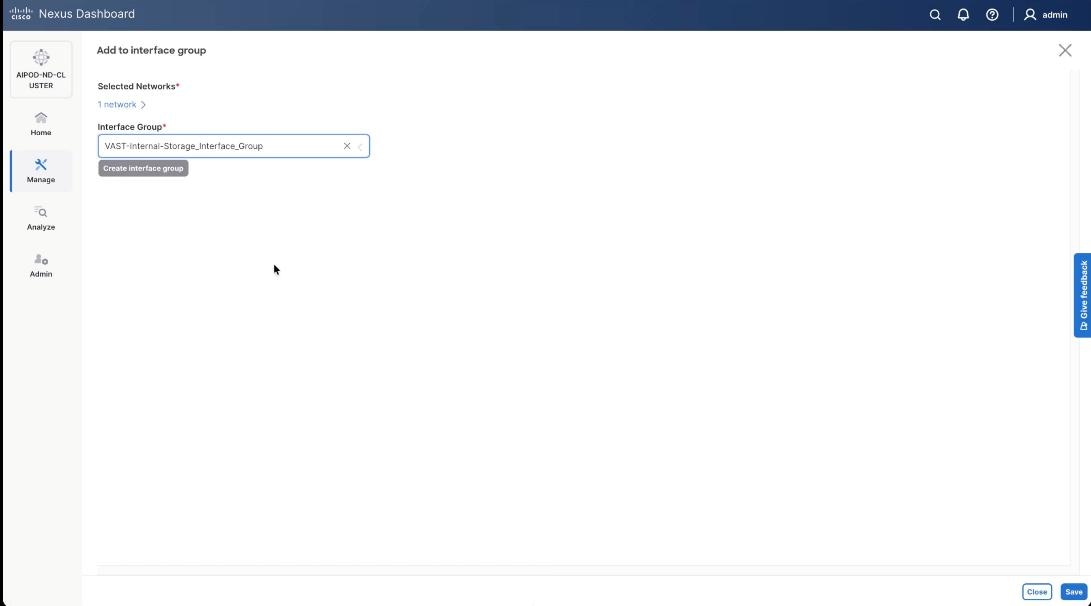
● Add ports to Interface groups: VAST-Internal-Storage_Interface_Group
● Attach VAST-Discovery_VNI_30010, add network to interface group and Deploy network on the storage leaf switches of the FE Fabric (FE-SLF1 and FE-SLF2)
● Attach VAST-Storage-Network_VNI_30069, add network to interface group and Deploy network on the storage leaf switches of the FE Fabric (FE-SLF1 and FE-SLF2)
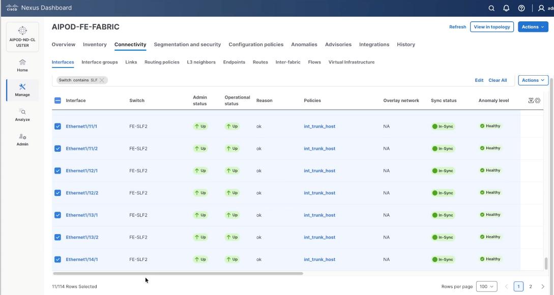
Step 1. Go to the Connectivity tab and select the ports 1/9/1 to 1/14/2 (VAST internal storage ports) . You can filter using storage leaf name (SLF) to narrow down the selection.
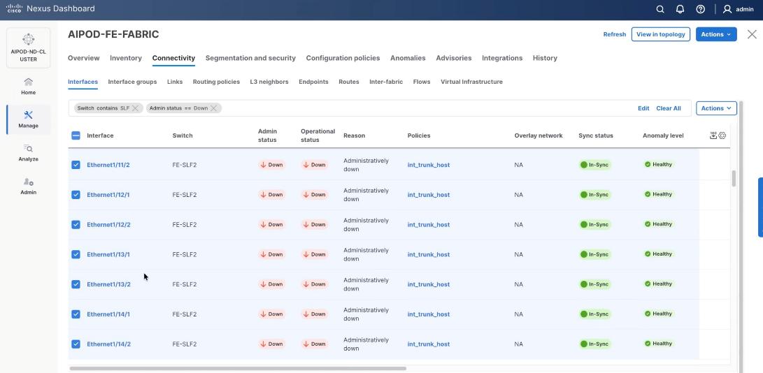
Step 2. When all VAST storage ports are selected, click Actions > Bulk Actions > Normalize.
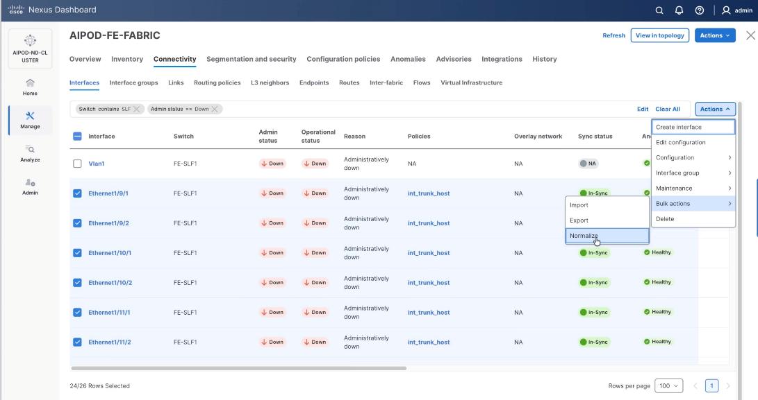
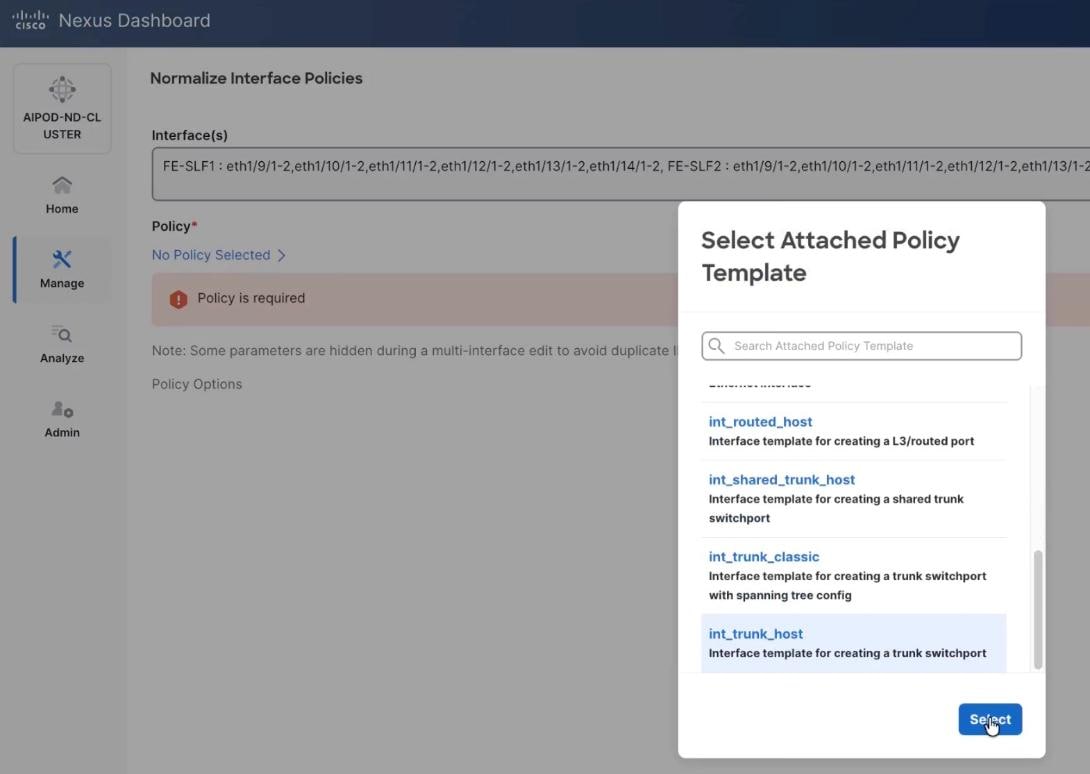
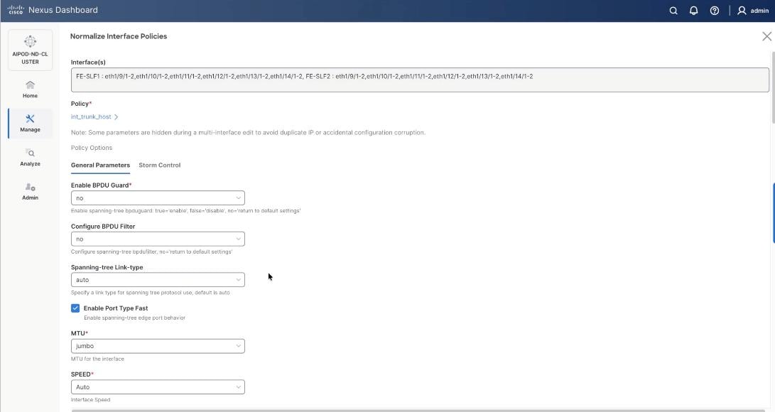
Step 3. Select trunk policy int_trunk_host. Select interface group as VAST-Storage-Network and click Save.
Step 4. On the Normalize interfaces Policy screen, scroll down to native vlan and enter native VLAN as 10 (VAST node discovery VLAN). Ensure Enable interface is checked. Click Save.
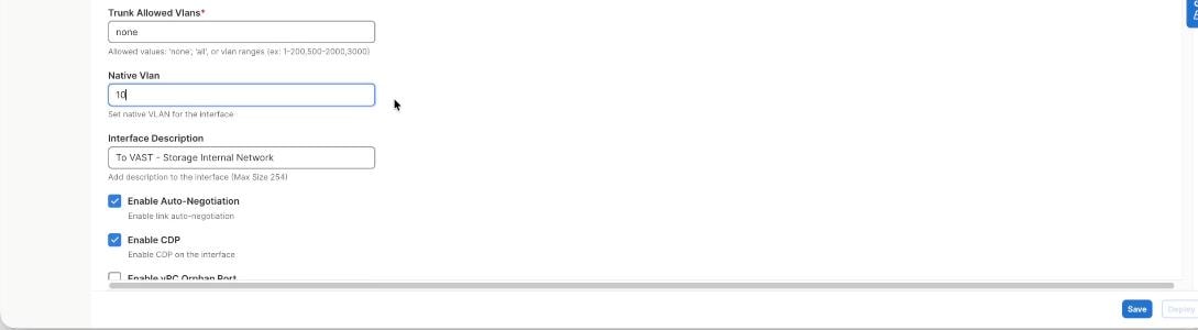
Step 5. Verify the changes to the ports with native VLAN as 10 and QoS Policies.
Step 6. Click Deploy Config.
Step 7. Ensure the storage port interfaces are up.
Step 8. From the navigation menu, go to Manage > Fabrics.
Step 9. Select the FE fabric and go to Connectivity > Interfaces tab.
Step 10. Select ports 1/9/1 to 1/14/2 on both FE-SLF1 and FE-SLF2. From the Action drop-down list, select interface group > Add.
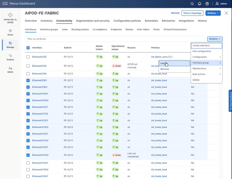
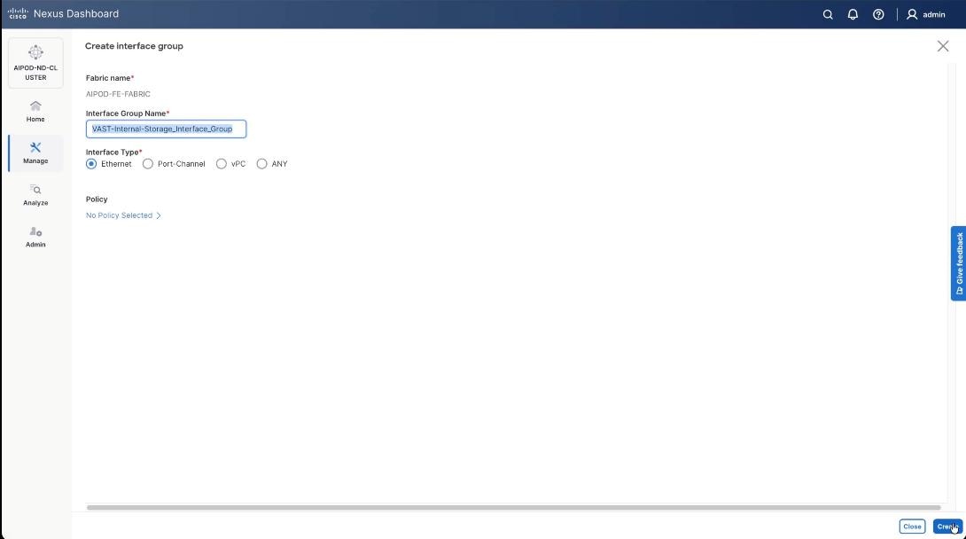
Step 11. Click create Interface group and name the interface group as VAST-Internal-Storage_Interface_Group, select interface type as ethernet. Click Create and then click Save.
Step 12. From the navigation menu, go to Manage > Fabrics.
Step 13. Select the FE fabric and go to Segmentation and Security > Networks tab.
Step 14. Select VAST discovery network, VAST-Discovery_VNI_30010, click the lower Actions button and select Add to interface group from the list.
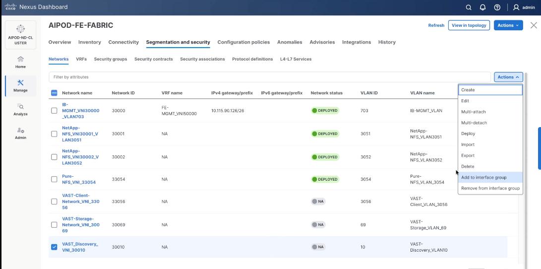
Step 15. Select the Interface group VAST-Internal-Storage_Interface_Group and click Save.
Step 16. Select VAST Discovery Network, click the Actions button and select the click Deploy.
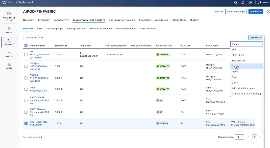
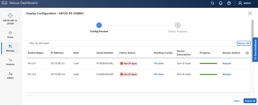
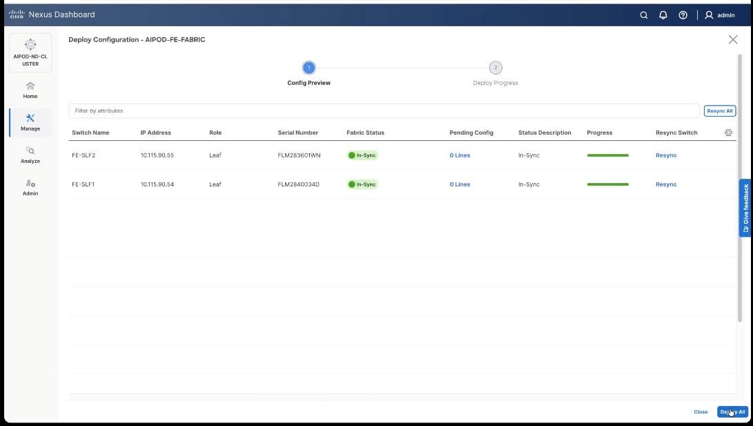
Step 17. From the Deploy Configuration screen, click Deploy.
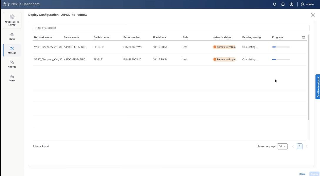
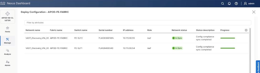
Step 18. Verify successful deployment and click Close.
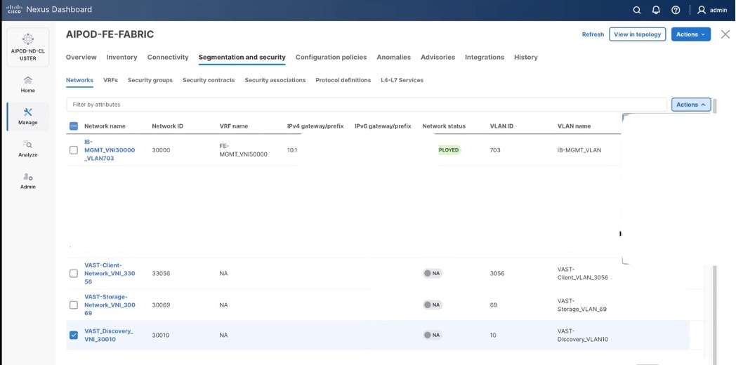
Step 19. Select the VAST discovery network, click the lower Actions button and select Multi-attach from the list.
Step 20. Select the FE_SLF1 and click Next.
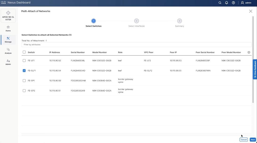
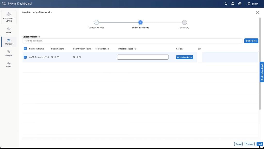
Step 21. Select VAST Discovery VNI and click Next.
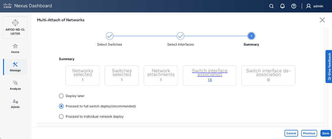
Step 22. Keep the default recommended option of Proceed to Full Switch Deployment and click Save.
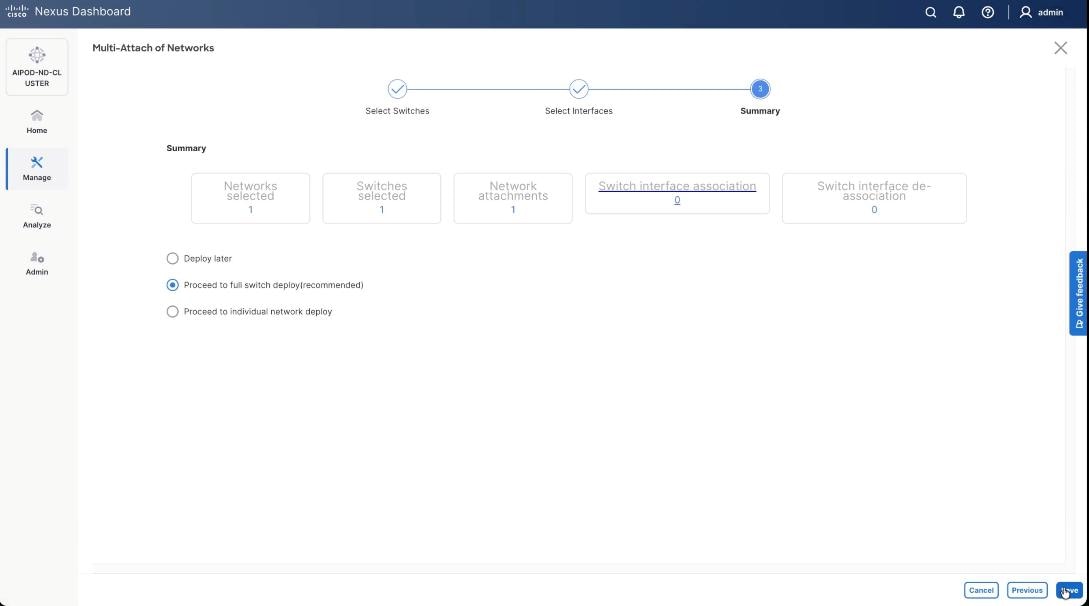
Step 23. Click Deploy All.
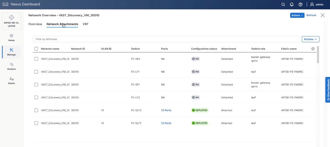
Step 24. Verify the port attachments to both Storage leaf.
Step 25. Select VAST internal storage network, VAST-Storage-Network_VNI_30069, click the lower Actions button and select Add to interface group from the list.
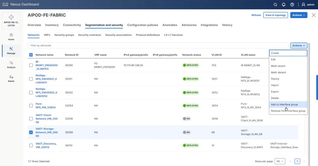
Step 26. Select the Interface group, VAST-Internal-Storage_Interface_Group and click Save.
Step 27. Select VAST Storage Network, click the Actions button and select Deploy.
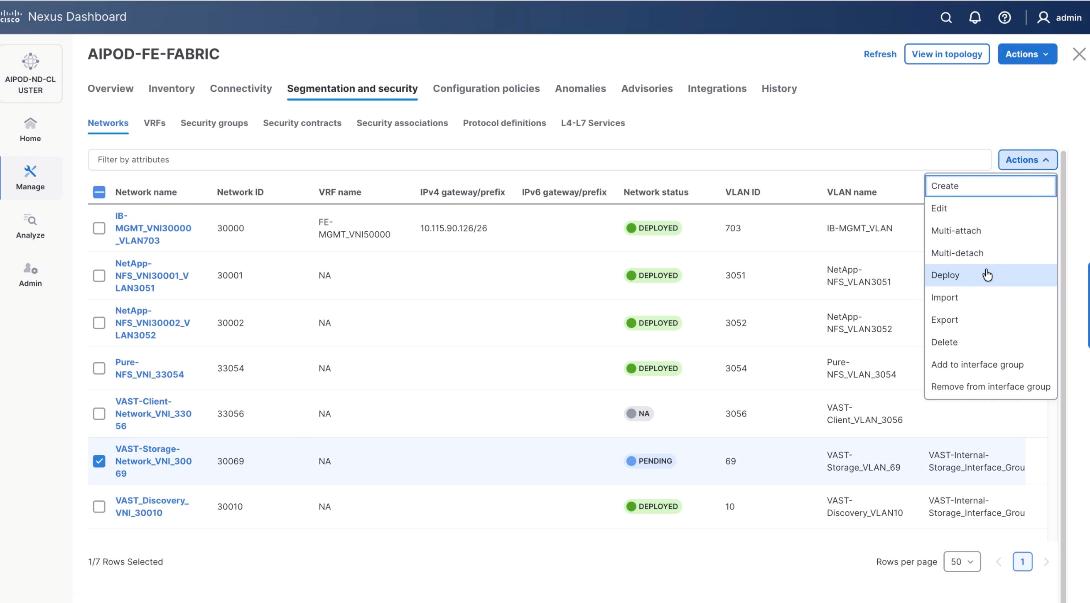
Step 28. From the Deploy Configuration screen, click Deploy.
Step 29. Verify the successful deployment and click Close.
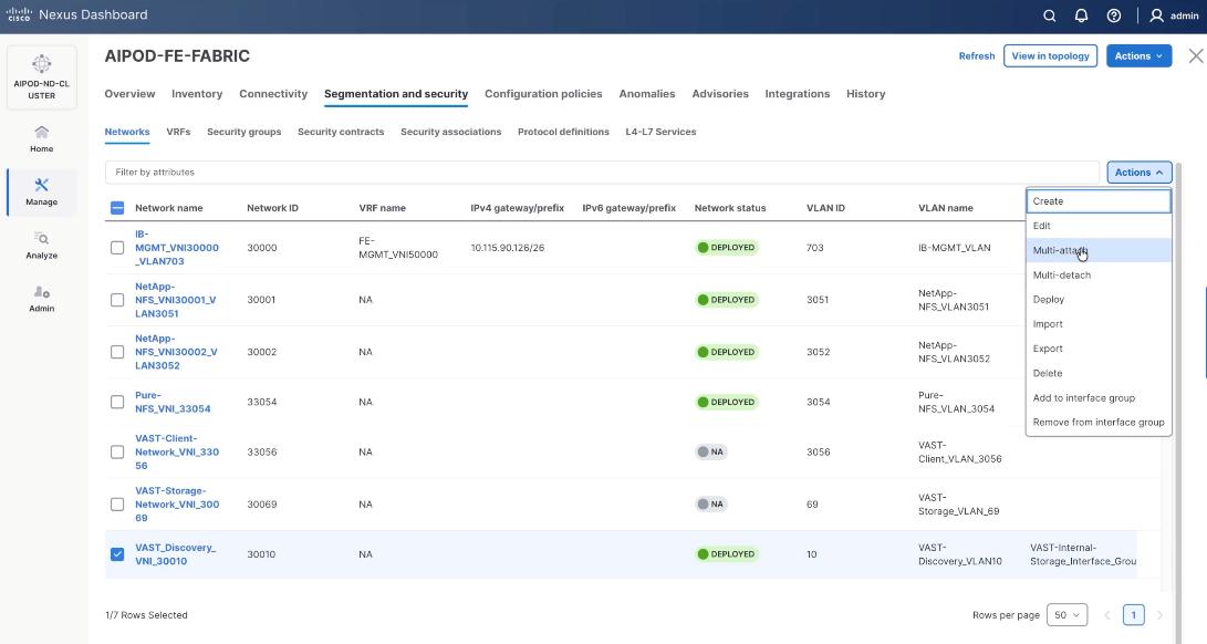
Step 30. Select the VAST storage network, click the lower Actions and select Multi-attach from the list.
Step 31. Select FE_SLF1 and click Next.
Step 32. Select VAST internal Storage VNI and click Next.
Step 33. Keep the default recommended option of Proceed to Full Switch Deployment and click Save.
Step 34. Click Deploy All.
Step 35. Verify successful the deployment of network VAST-Discovery_VNI_30010 and click Close.
Procedure 4. Deploy VAST External Client Network
This procedure details the following:
● Add ports and network to Interface groups: VAST-Client-Network
● Attach VAST-Client-Network_VNI_33056, add network to interface group and Deploy network on the front end Fabric (FE-Fabric)
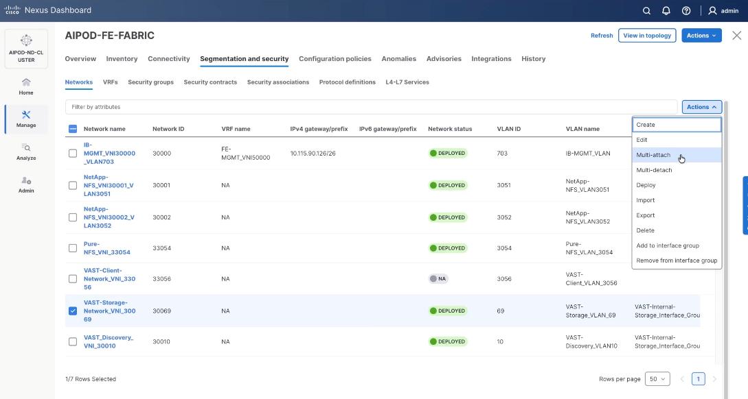
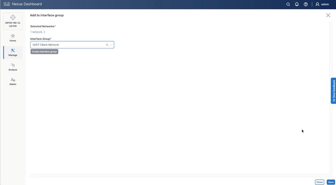
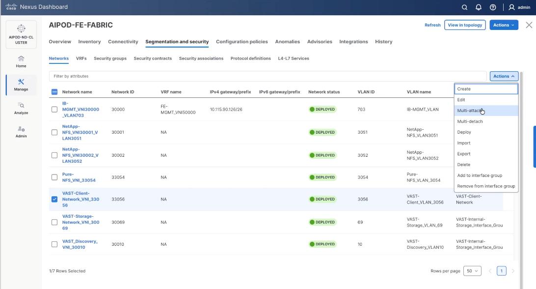
Step 1. Select the VAST discovery network VAST_Client-Network_VNI_33056, click the lower Actions button and select Add to interface group from the list.
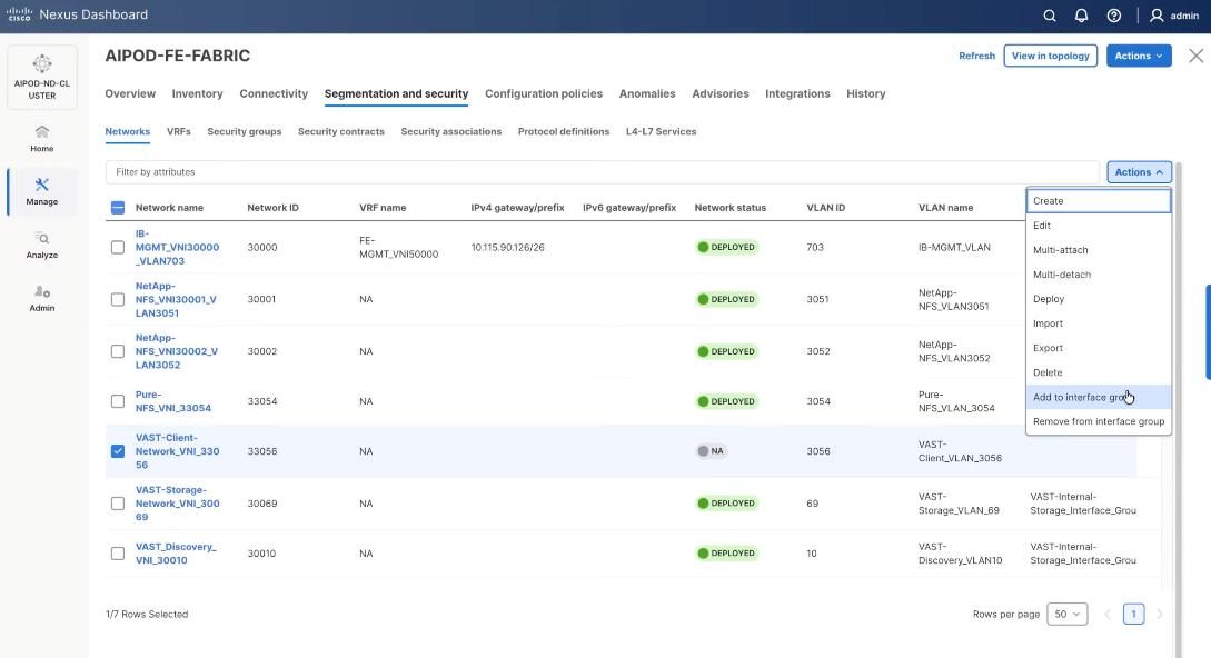
Step 2. Select the Interface group VAST-Client-Network and click Save. If it doesn’t exist create the interface group.
Step 3. Select VAST Client Network, click the Actions button and select Deploy.
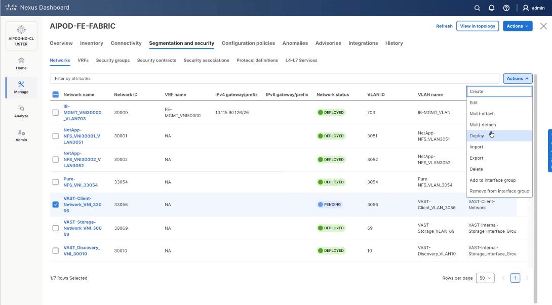
Step 4. From the Deploy Configuration screen, click Deploy.
Step 5. Verify a successful deployment and click Close.
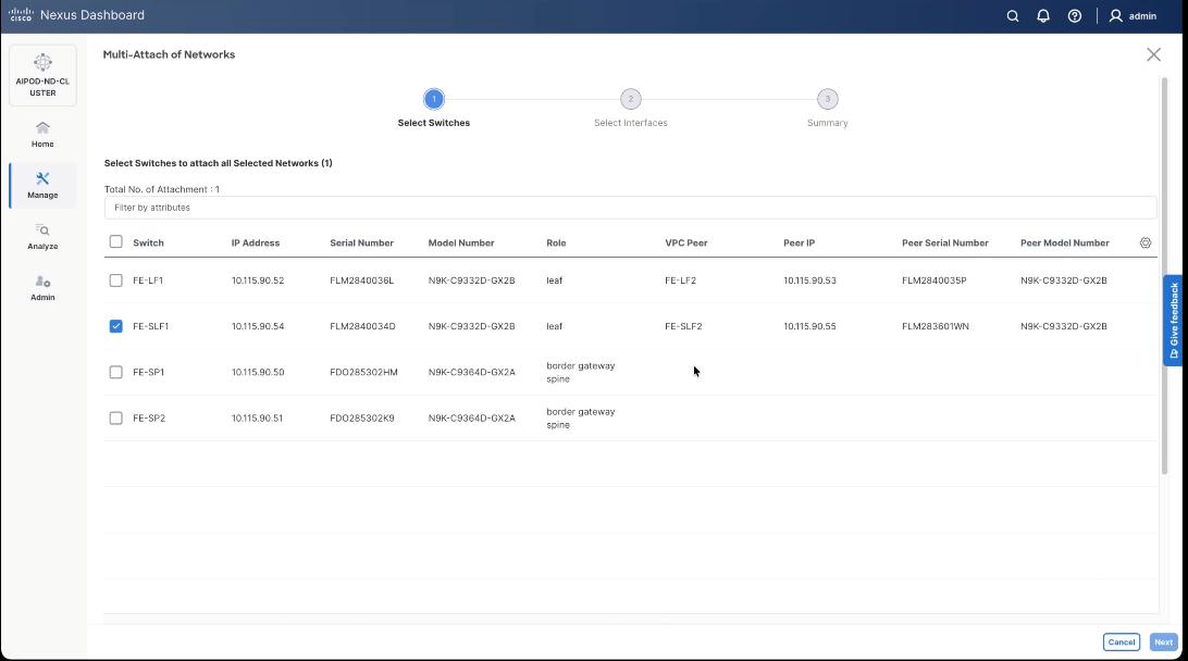
Step 6. Select the VAST Client network VAST-Client-Network_VNI_33056, click the lower Actions button and select Multi-attach from the list.
Step 7. Select the FE_SLF1 and click Next.
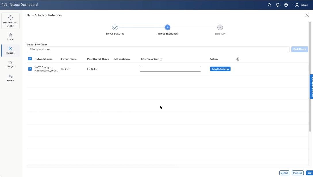
Step 8. Add the VAST client network to the port channel interfaces for the GPU nodes connected to the FE-LF1 and FE-LF2 client leaf switches. In the existing deployment theses are port channel 111, port channel 112, port channel 113 and port channel 114. Also add the BCM nodes and X-Series management nodes to allow access to VAST client network.
Step 9. Select the VAST-Client-Network and click Select interfaces.
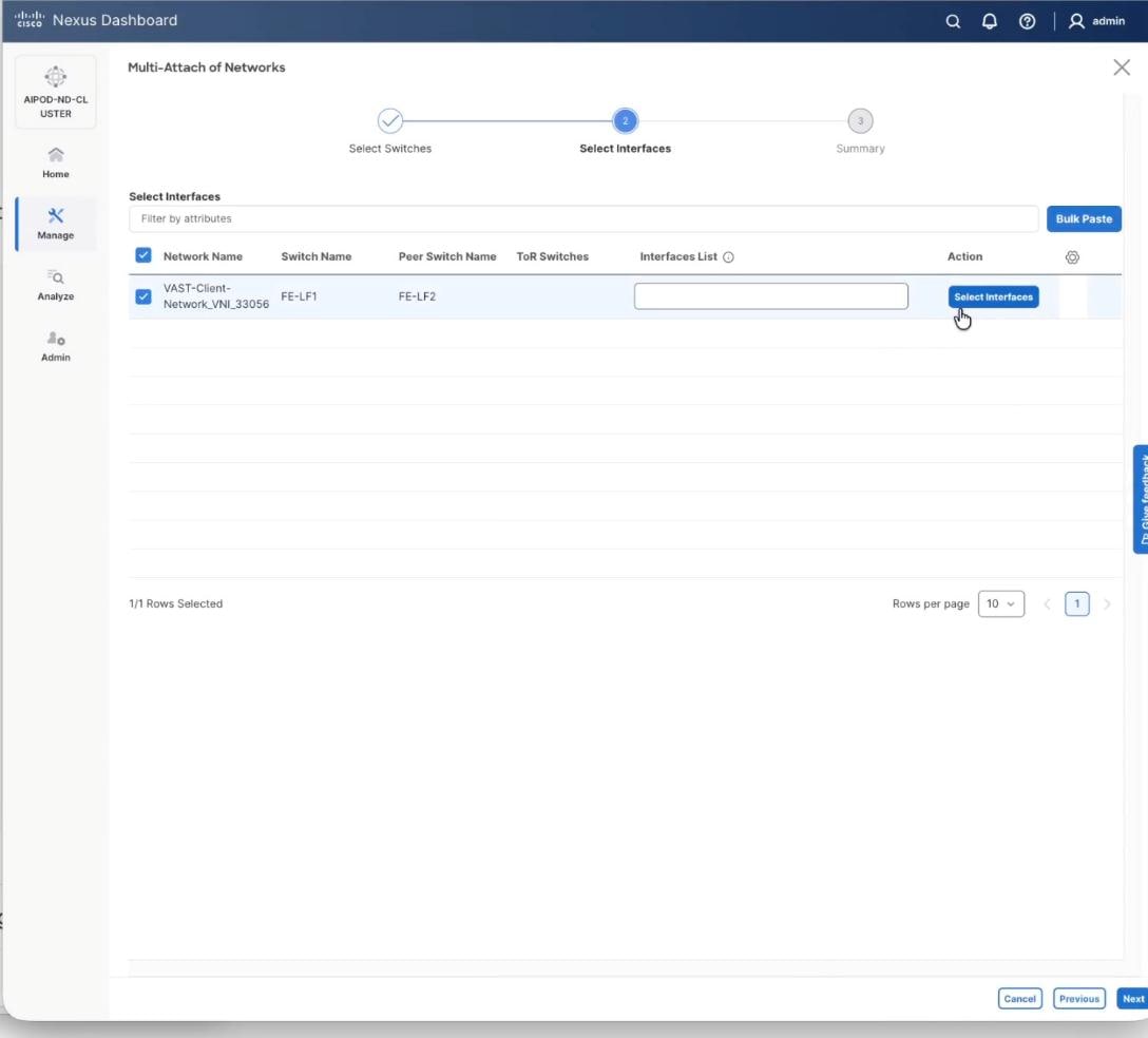
Step 10. Select the port channel interfaces for 4x C885 GPU nodes on FE-LF1 and FE-LF2 . Also add the BCM nodes and X-Series management nodes to allow access to VAST client network. Click Save.
Step 11. Verify the port channel and click Next.
Step 12. Click Save.
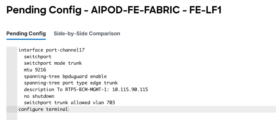
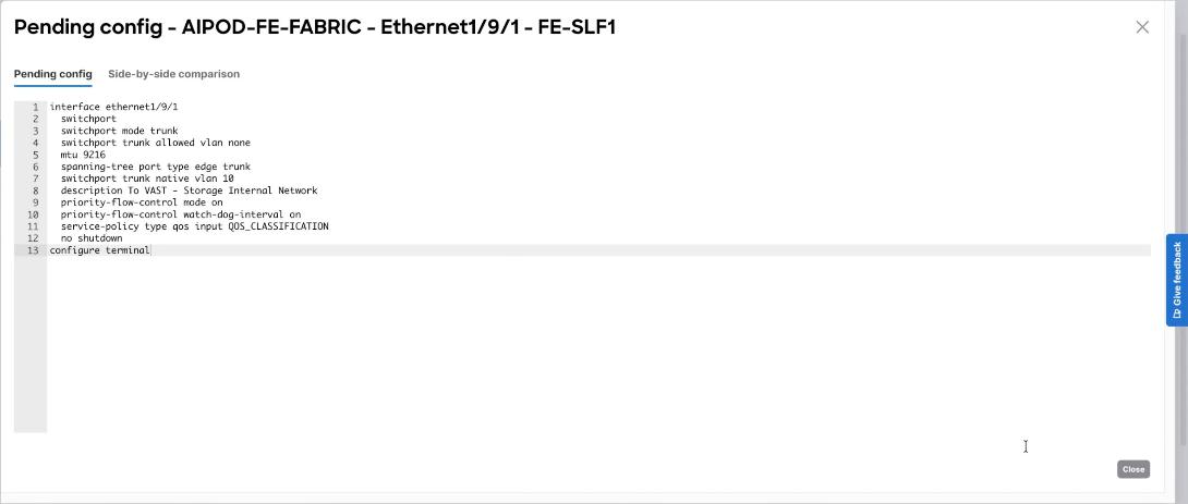
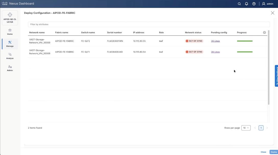
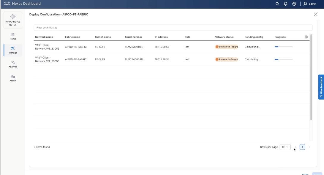
Step 13. The configuration to deploy is shown below. Click Pending Config to see the configuration being deployed. The pending configuration on one leaf switch is provided as a reference at the end. Click Deploy All.
Step 14. Click Close.
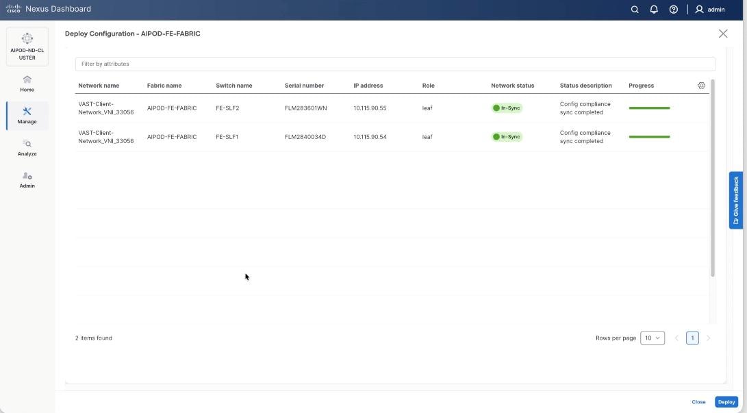
Step 15. Verify a successful deployment.
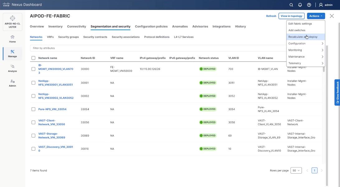
Step 16. Verify a successful deployment and propagation of configurations from Nexus Dashboard controller to nexus switches. Select the FE fabric and go to Segmentation and Security > Networks. Click Action and click Recalculate and Deploy.
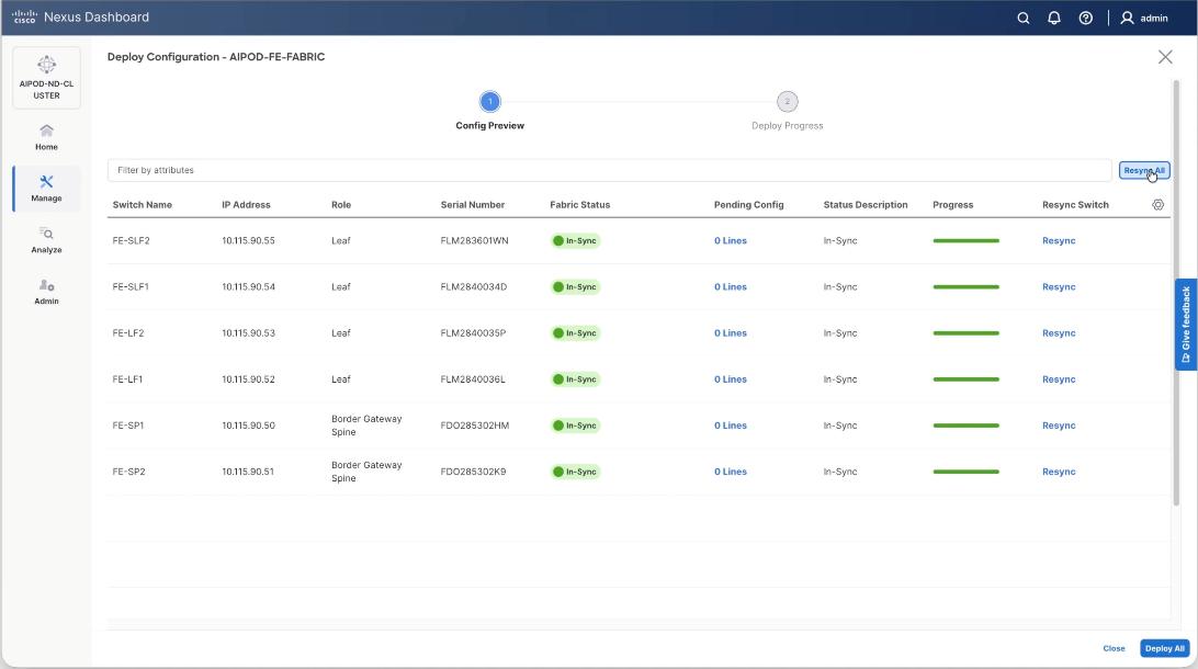
Step 17. Verify in-sync status of FE Fabric.

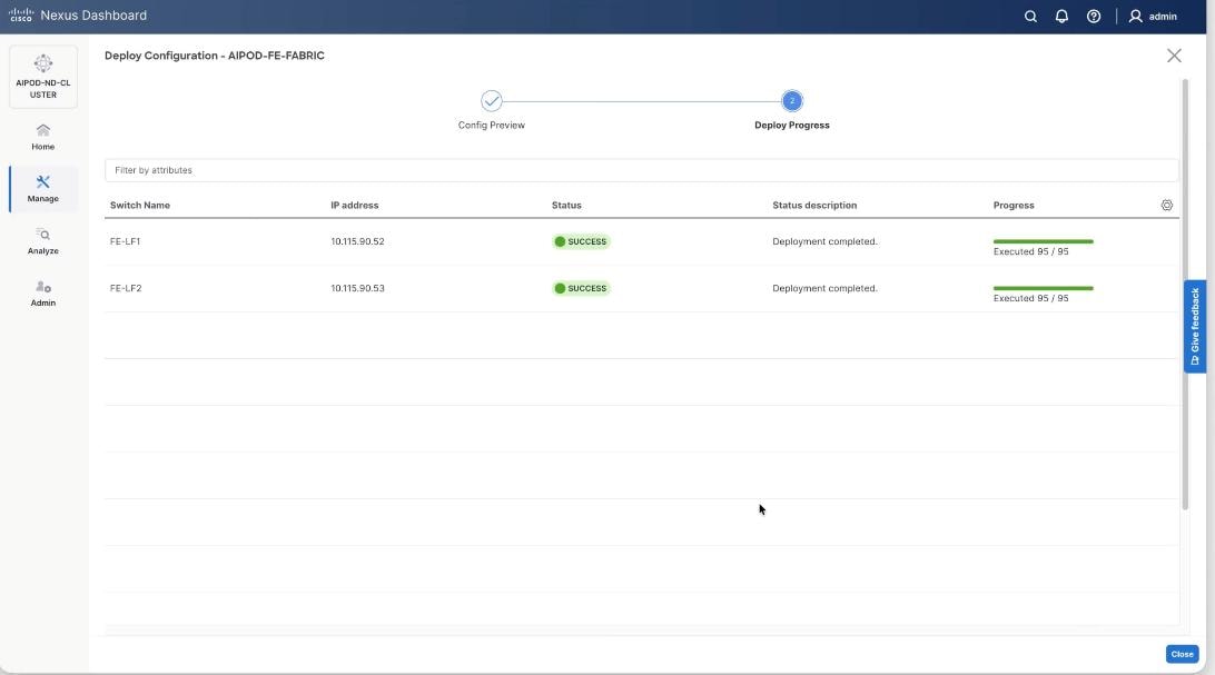
Step 18. Click Resync All to confirm synchronization of FE Fabric.
Cisco Nexus Backend Fabric Setup
In this setup, the Nexus Backend Fabric consisted of 2 spine and 2 leaf switches. This fabric was cabled according to Table 4. The fabric switch details are listed in Table 18.
Table 18. Backend Fabric Switch Details
| Switch |
Role |
OOB IP |
Firmware |
Model |
| BE-LF1 |
Leaf |
10.115.90.58 |
10.4(5) |
Cisco Nexus 9332D-GX2B |
| BE-LF2 |
Leaf |
10.115.90.59 |
10.4(5) |
Cisco Nexus 9332D-GX2B |
| BE-SP1 |
Spine |
10.115.90.60 |
10.4(5) |
Cisco Nexus 9364D-GX2A |
| BE-SP2 |
Spine |
10.115.90.61 |
10.4(5) |
Cisco Nexus 9364D-GX2A |
Physical Connectivity
Note: Follow the physical connectivity guidelines in the Connectivity Design section.
Initial Configuration of Switches
The following procedures describe this basic configuration of the Cisco Nexus backend fabric switches for use in the solution. This procedure assumes the use of Cisco Nexus 9000 10.4(5), the Cisco suggested Nexus switch release at the time of this validation.
Procedure 1. Set Up Initial Configuration from a serial console
Step 1. Set up the initial configuration for each backend fabric switch as listed in Table 18.
Step 2. Configure the switch.
Note: On initial boot, the NX-OS setup automatically starts and attempts to enter Power on Auto Provisioning.
Abort Power On Auto Provisioning [yes - continue with normal setup, skip - bypass password and basic configuration, no - continue with Power On Auto Provisioning] (yes/skip/no)[no]: yes
Disabling POAP.......Disabling POAP
poap: Rolling back, please wait... (This may take 5-15 minutes)
---- System Admin Account Setup ----
Do you want to enforce secure password standard (yes/no) [y]: Enter
Enter the password for "admin": <password>
Confirm the password for "admin": <password>
Would you like to enter the basic configuration dialog (yes/no): yes
Create another login account (yes/no) [n]: Enter
Configure read-only SNMP community string (yes/no) [n]: Enter
Configure read-write SNMP community string (yes/no) [n]: Enter
Enter the switch name: <nexus-hostname>
Continue with Out-of-band (mgmt0) management configuration? (yes/no) [y]: Enter
Mgmt0 IPv4 address: <nexus-out_of_band_mgmt0-ip>
Mgmt0 IPv4 netmask: <nexus-mgmt0-netmask>
Configure the default gateway? (yes/no) [y]: Enter
IPv4 address of the default gateway: <nexus-mgmt0-gw>
Configure advanced IP options? (yes/no) [n]: Enter
Enable the telnet service? (yes/no) [n]: Enter
Enable the ssh service? (yes/no) [y]: Enter
Type of ssh key you would like to generate (dsa/rsa) [rsa]: Enter
Number of rsa key bits <1024-2048> [2048]: Enter
Configure the ntp server? (yes/no) [n]: Enter
Configure default interface layer (L3/L2) [L2]: Enter
Configure default switchport interface state (shut/noshut) [noshut]: Enter
Enter basic FC configurations (yes/no) [n]: n
Configure CoPP system profile (strict/moderate/lenient/dense) [strict]: Enter
Would you like to edit the configuration? (yes/no) [n]: Enter
Step 3. Review the configuration summary before enabling the configuration.
Use this configuration and save it? (yes/no) [y]: Enter
Step 4. Repeat this configuration for all switches listed in Table 18.
Deploy BE Cluster
Procedure 1. Deploy BE Cluster
Step 1. From a web browser go to Nexus Dashboard. Use the management IP of any node in the ND cluster. Log in using admin account.
Step 2. Go to Manage > Fabrics.
Step 3. Click Actions.
Step 4. Select Create Fabric from the drop-down list.
Step 5. Select Create a new LAN fabric.
Step 6. Click Next.
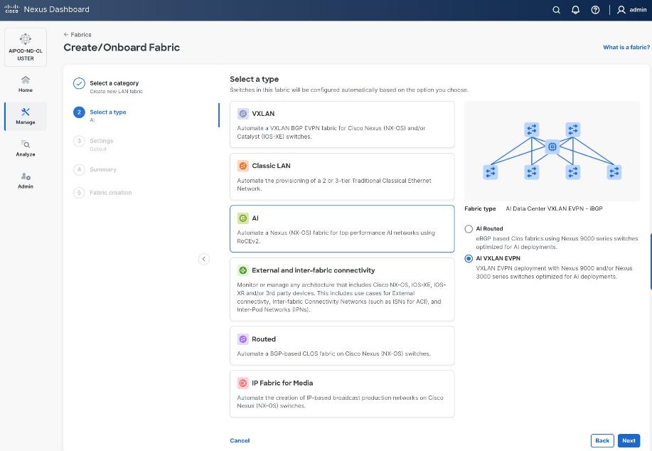
Step 7. For the Backend (E-W) AI/ML fabric, select AI > AI VXLAN EVPN to manage and setup a high-speed 400GbE/800GbE fabric for GPU-to-GPU connectivity.
Step 8. Click Next.
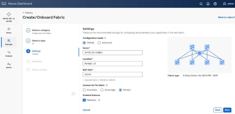
Step 9. To configure the Backend (BE) fabric, under Configuration Mode, specify the following:
● Leave the radio button enabled for Default.
● Specify Name, Location, and BGP ASN#.
● Select one of the Licensing options for the fabric – click the ? icon to get more details on the options.
● (Optional) Enable Telemetry feature.
Step 10. Enable the radio button for Advanced in the Configuration Mode section to see additional configuration options for the fabric.
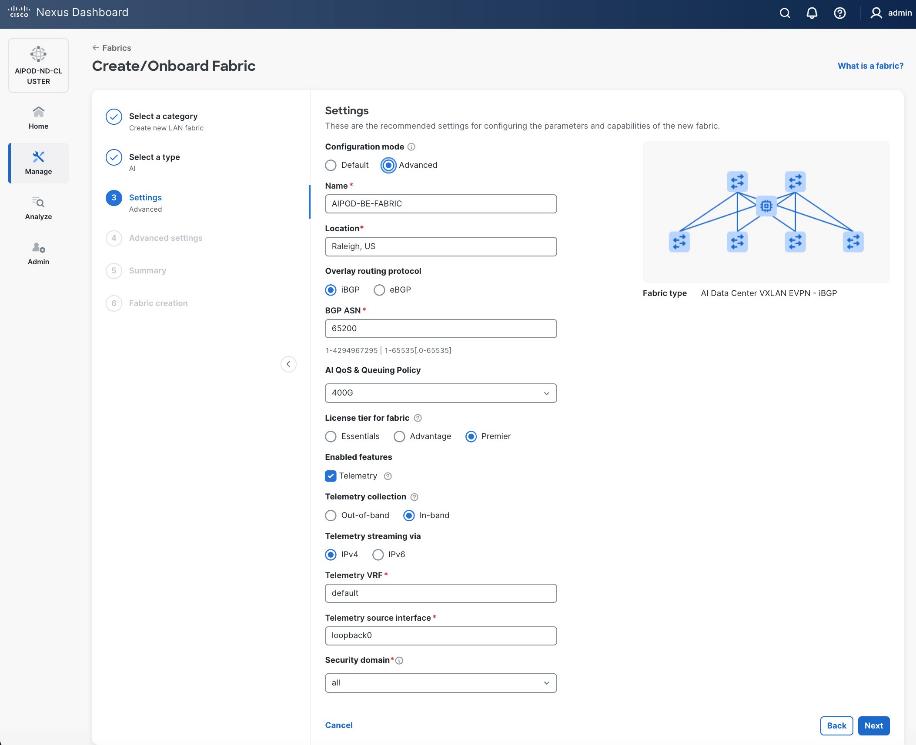
Step 11. Verify QoS and Telemetry settings reflect your setup.
Step 12. In the Advanced Settings menu, select the Resource tab.
Step 13. Click Next.
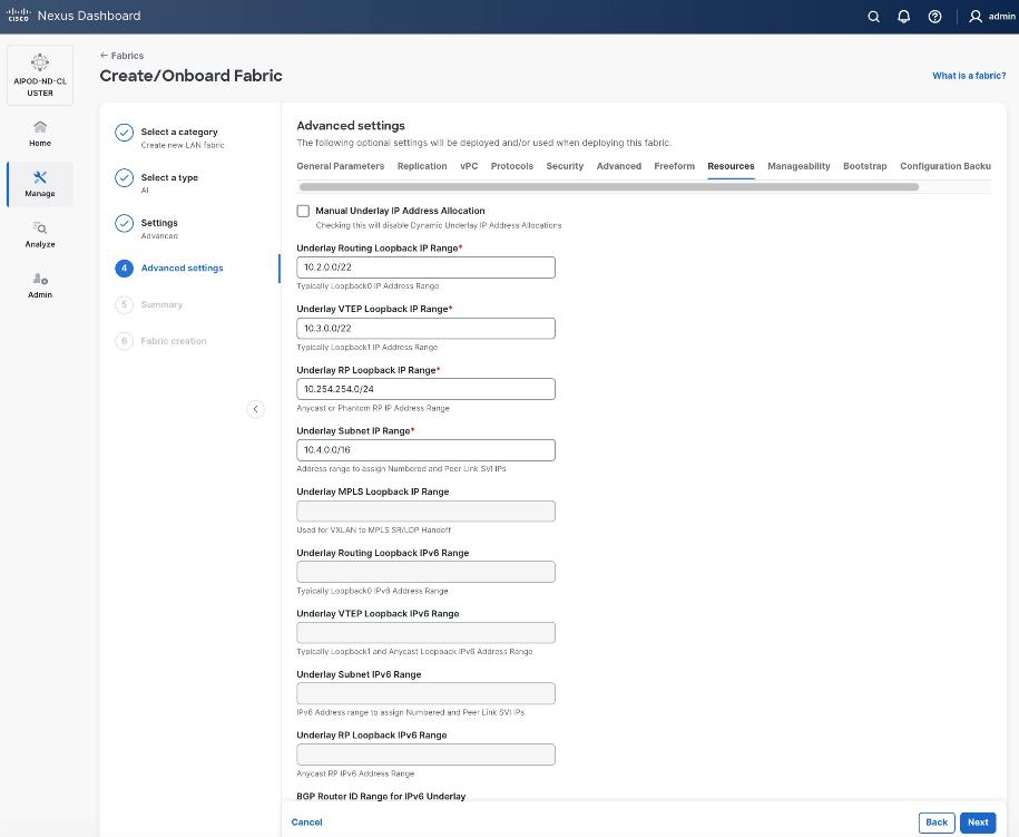
Step 14. Change the IP address for this fabric from the default values to prevent overlap with frontend fabric, also managed by the same Nexus Dashboard. For this CVD validation, the first octet was changed from 10 to 20. The Backend fabric is isolated from other networks with no external connectivity so it could be kept as frontend but there will be alerts and warnings on Nexus dashboard, so the change is primarily done for this reason.
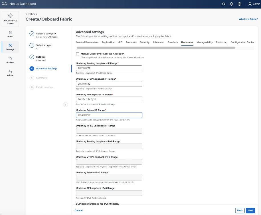
Step 15. Scroll down and change the VRF Lite Subnet IP Range.
Step 16. Click Next.
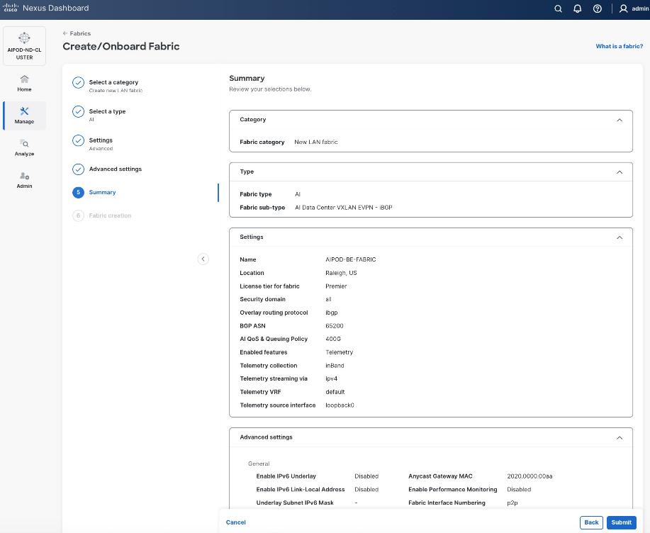
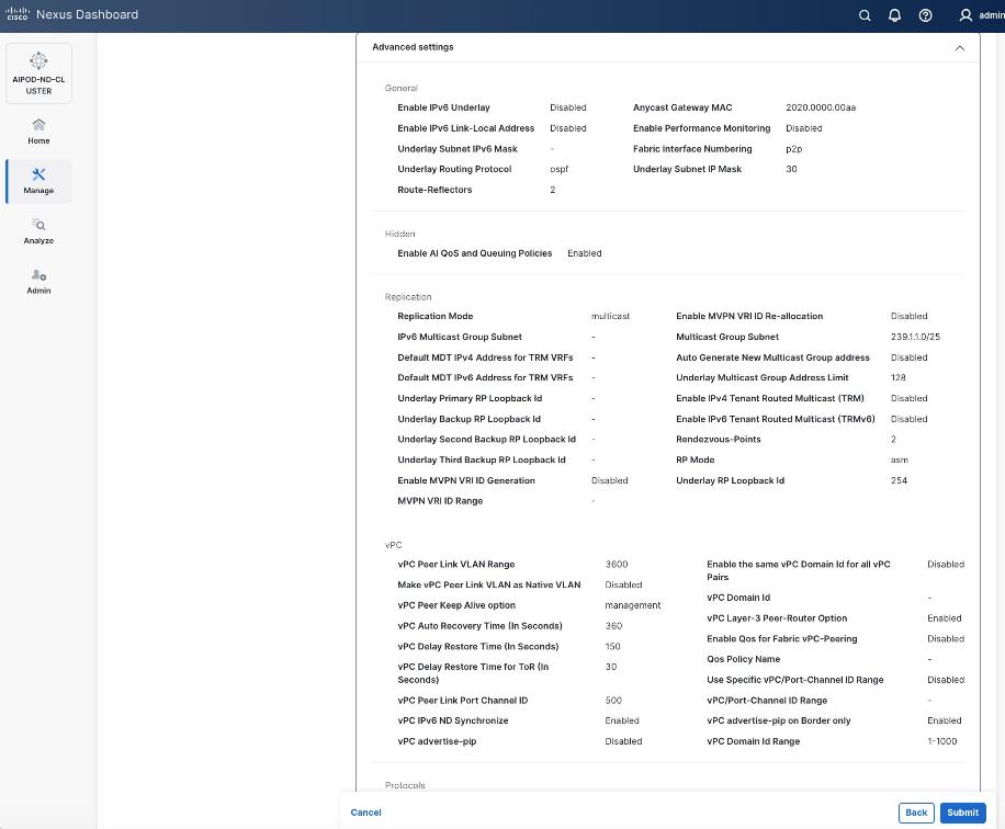
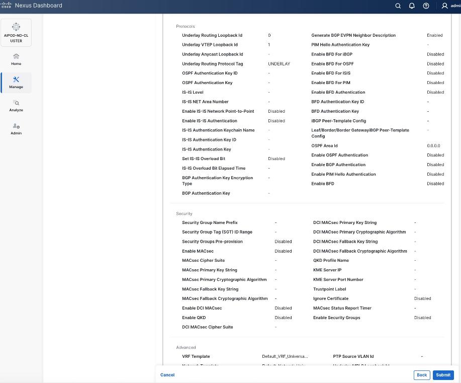
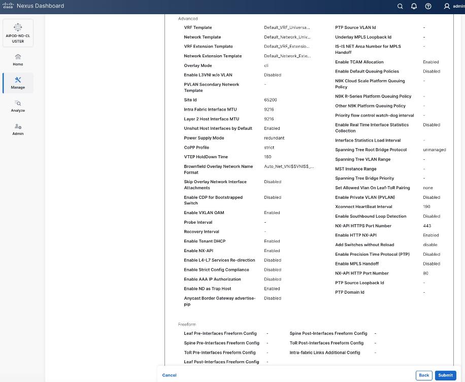
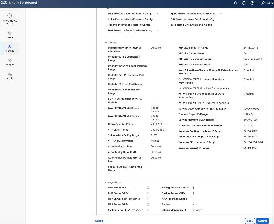
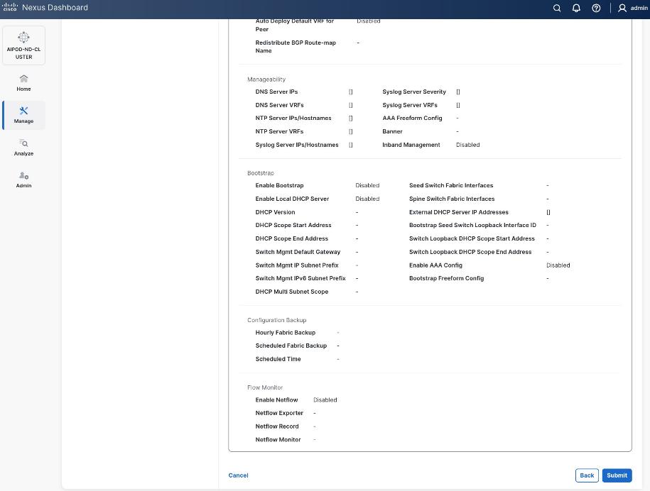
Step 17. Review the Fabric Summary settings.
Step 18. Click Submit.
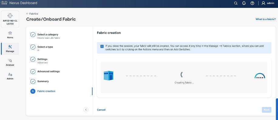
Step 19. Wait for the Fabric creation to complete.
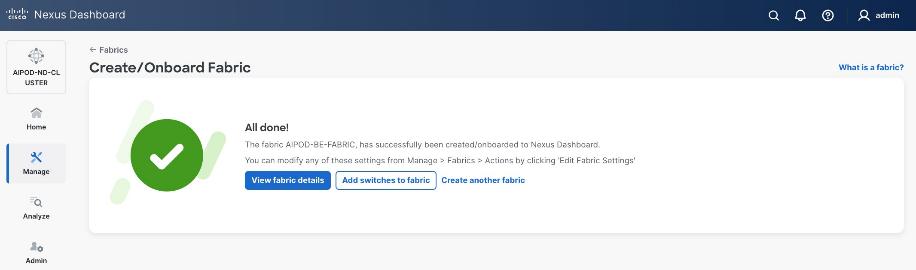
Step 20. Click View Fabric Details to see the dashboard for the newly created BE Fabric.
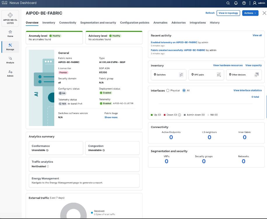
Step 21. Select Manage > Fabrics and then select the BE fabric. From the Actions drop-down list, select Edit fabric settings. Select the Fabric management tab and the Manageability tab underneath. Add the NTP Server IPs and the NTP Server VRF (management) and click Save.
Step 22. Select the Freeform tab and optionally enter the info shown in the screenshot modified for your timezone. Click Save.
Procedure 2. Add Spine and Leaf switches to the BE Fabric
Step 1. If you want to add switches without a reload, go to Manage > Fabrics.
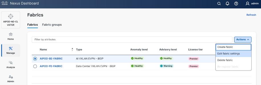
Step 2. From the Actions menu, select Edit Fabric Settings.
Step 3. Click Fabric Management > Advanced tabs and scroll down to find the field for Add switches without Reload and change setting to Enable. Click Save.
Step 4. In the Warning message, click Got it.
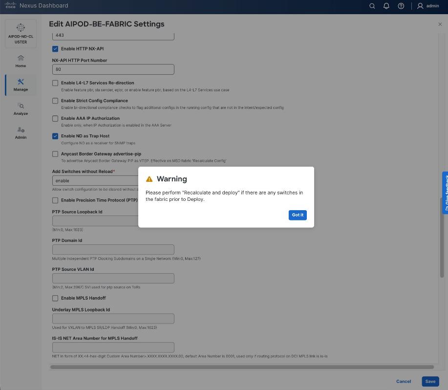
Step 5. From the Manage > Fabrics view, click the BE fabric name to add switches to the fabric.
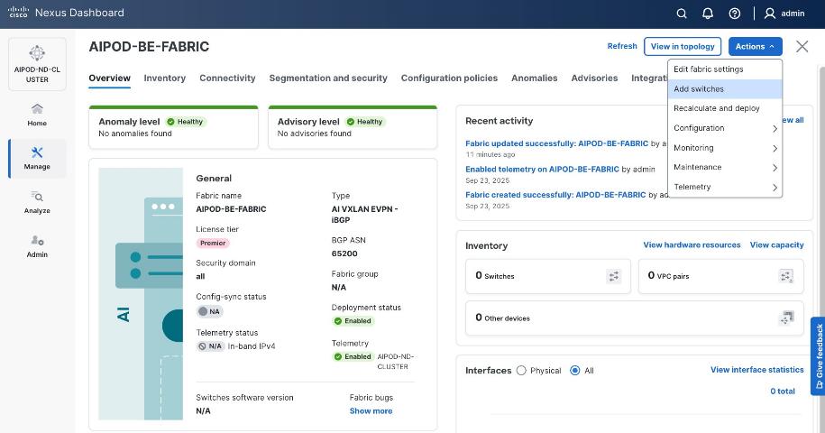
Step 6. Click Actions > Add switches. Specify the following:
● Seed IP
● Username and Password
● Number of hops
● Uncheck Preserver Config
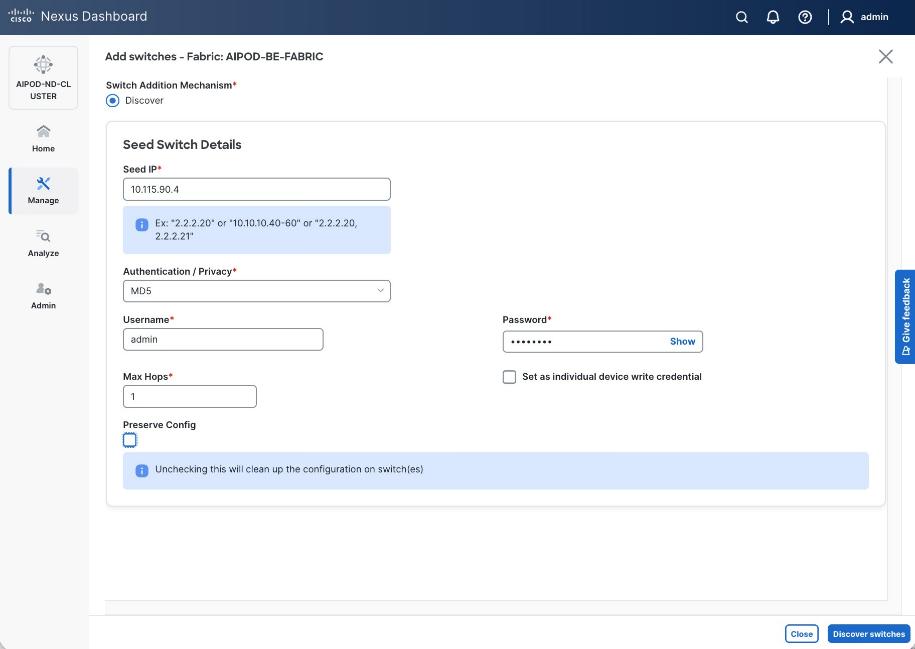
Step 7. Click Discover Switches.
Step 8. Click Confirm. Filter the discovered switch list as needed to view just the switches you want to add.
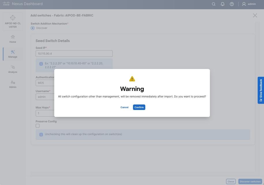
Step 9. Select the switches to add to the BE Cluster.
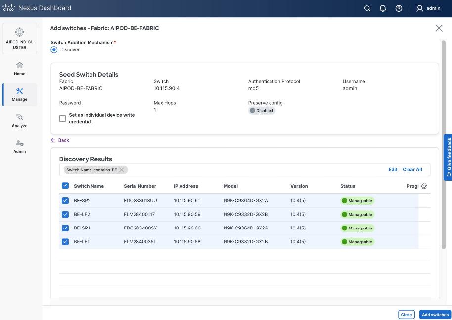
Step 10. Click Add Switches.
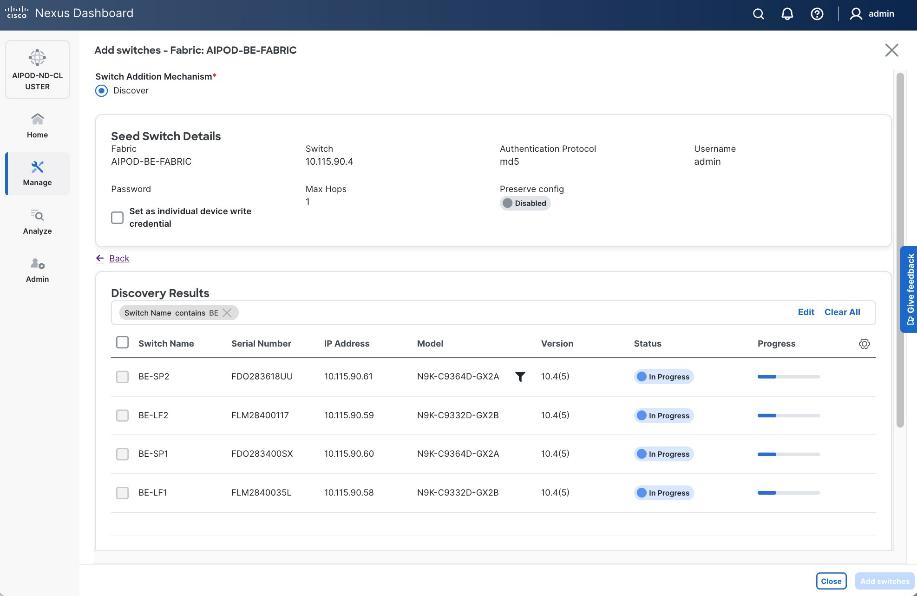
Step 11. When the Status changes from Status to Switch Added, click Close.
Step 12. From the Manage > Fabrics, select the fabric and click Inventory tab.
Step 13. For each switch in the list, verify Role is correct.
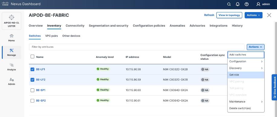
Step 14. To change the role, select the switch and then click Actions and select Set role from the drop-down list.
Step 15. In the Select Role pop-up window, select the correct role from the list and click Select.
Step 16. Click OK in the pop-up warning to perform Recalculate and deploy to complete the change.
Step 17. Repeat steps 14-16 to select role for all switches in the fabric.
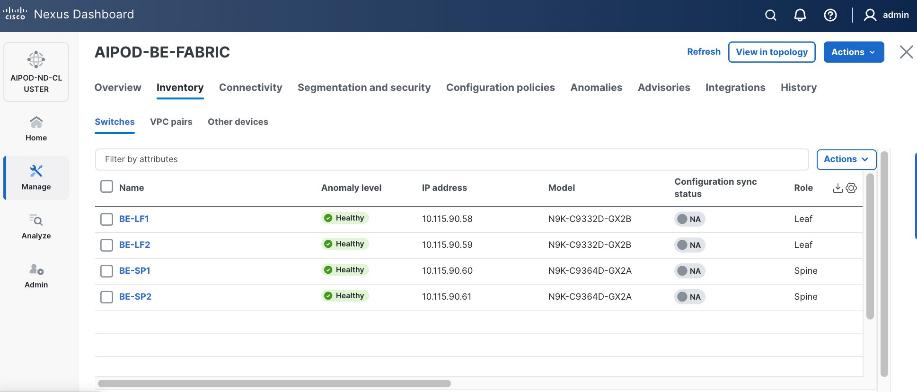
Step 18. Click the main Actions button and select Recalculate and deploy from the drop-down list. If it says one is already in progress, wait a few minutes and repeat the steps.
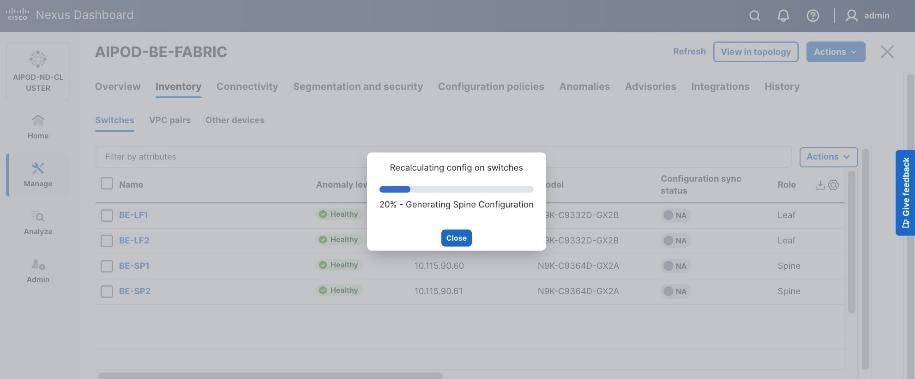
You should see the Fabric as Out-of-sync with some Pending Config (lines of config) changes from the recalculation as shown below:
Step 19. Click the Pending Config lines for any of the switches to view the exact changes that will be deployed. Click Close.
Step 20. Click Deploy All.
Step 21. When the configuration deployment completes successfully, click Close.
Procedure 3. Review fabric state and upgrade software as needed
ND may identify issues in hardware, connectivity, software and so on, reflected by the Anomaly level. To view the flagged anomalies, go to Anomalies in the top menu bar. Address each anomaly to prevent issues later, either by resolving them or acknowledging them.
Step 1. Review the Advisories and resolve or acknowledge them.
Step 2. Evaluate and upgrade to the most current Cisco recommended Nexus OS release.
The BE fabric is now ready for connecting to UCS GPU nodes to enable GPU-to-GPU communication across the BE fabric.
Modify QoS Policy on BE fabric
Assumptions and Prerequisites
Assumes that you have selected the AI Fabric template with default QoS policy enabled. This section will modify this default policy for the software version used in this CVD.
Setup Information
Table 19. Setup Information for BE Fabric QoS
| Parameter Type |
Parameter Name | Value |
Parameter Type / Other Info |
| QoS Policy Template |
|
|
| Default/Original Policy Template Name |
400G | AI_Fabric_QOS_400G |
|
| New Policy Template Name |
AIPOD-BE-QOS-400G |
|
| PFC MTU |
9216 |
Default for this release: 4200 |
| Bandwidth Percent for ‘c-out-8q-q3’ |
90 |
Default = 50 |
| Bandwidth Percent for ‘c-out-8q-q-default’ |
90 |
Default = 50 |
Deployment Steps
To change the QoS policy deployed in the backend fabric, follow the procedures below using the setup information provided in Table 19.
Procedure 1. Create new template from default QoS policy template
Step 1. From a web browser go to Cisco Nexus Dashboard. Use the management IP of any node in the ND cluster. Log in using admin account.
Step 2. Go to Manage > Template Library.
Step 3. Filter on ‘QOS’ in top search bar.
Step 4. Select the default QoS policy that was applied when the BE fabric was deployed using the default AI fabric template.
Step 5. Click Actions.
Step 6. Select Duplicate template from the drop-down list.
Step 7. In the Template Properties section, specify a new name for the QoS policy template.

Step 8. In the Template Content section, modify the bandwidth percent for two queues: c-out-8q-q3 to 90 and c-out-8q-q to 10. Scroll down and change PFC MTU to 9216.
Note: Bandwidth Percent for the above queues can be adjusted as needed for your environment.
Step 9. Go to Manage > Fabrics. Select the BE fabric from the list and click on the BE fabric name.
Step 10. Navigate Actions and Edit Fabric Settings from the drop-down list. In the General tab, select the new QoS policy template from the drop-down list for AI QoS & Queueing Policy.
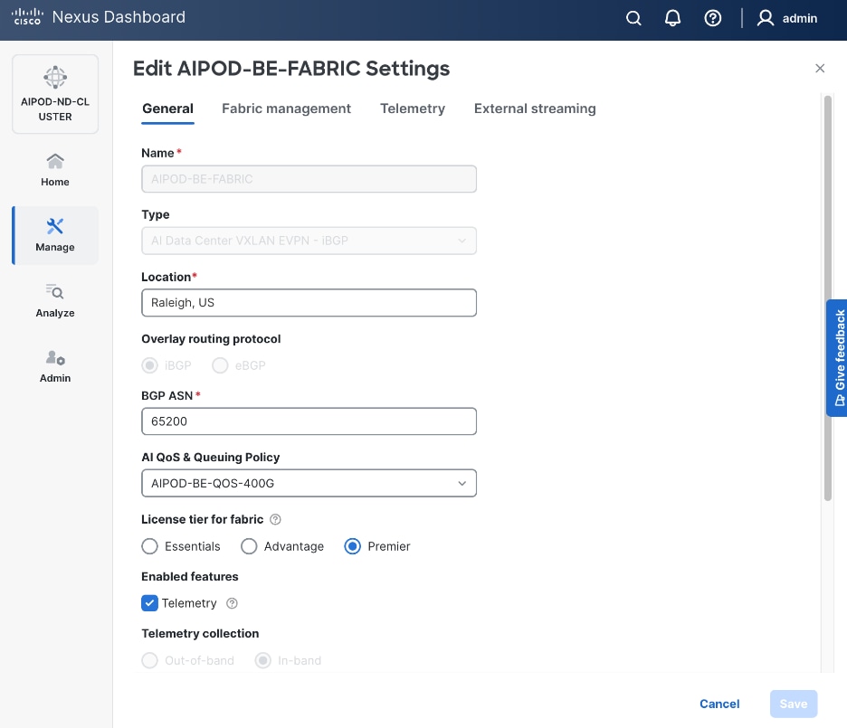
Enable GPU-to-GPU Networking between UCS GPU nodes across BE Fabric
Assumptions and Prerequisites
Setup Information
Table 20. Setup Information for GPU-to-GPU networking across BE Fabric
| Parameter Type |
Parameter Name | Value |
Parameter Type / Other Info |
| BE Network |
|
|
| Network Name |
BE-MLPerf_VNI_33590 |
|
| Layer 2 Only |
Enable checkbox |
|
| Network ID |
33590 |
|
| VLAN ID |
3590 |
|
| VLAN Name |
BE-MLPerf_VLAN_3590 |
|
| Interface Description |
BE-MLPerf_VLAN |
|
| Ports Connecting to UCS Servers |
Assumed to be same on all leaf switches |
|
| Interface List |
Ethernet 1/1-8 |
|
| Port type |
Access port (int_access_host) |
Default = trunk port (int_trunk_host) |
| Enable port type fast |
Enable checkbox |
|
Deployment Steps
To enable GPU-to-GPU network between UCS GPU nodes across the backend fabric, follow the procedures below using the setup information provided in Table 20.
Procedure 1. Configure ports going to UCS GPU nodes
Step 1. Filter the relevant interfaces going to UCS GPU nodes.
Step 2. Select the ports. Click the second of two Actions and select Configuration > Shutdown from the drop-down list to administratively shut the ports going to UCS GPU nodes.
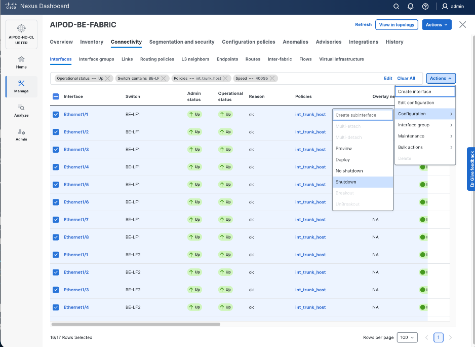
Step 3. Select the shutdown ports. Click the second of two Actions and select Edit Configuration to configure all ports going to UCS GPU nodes.
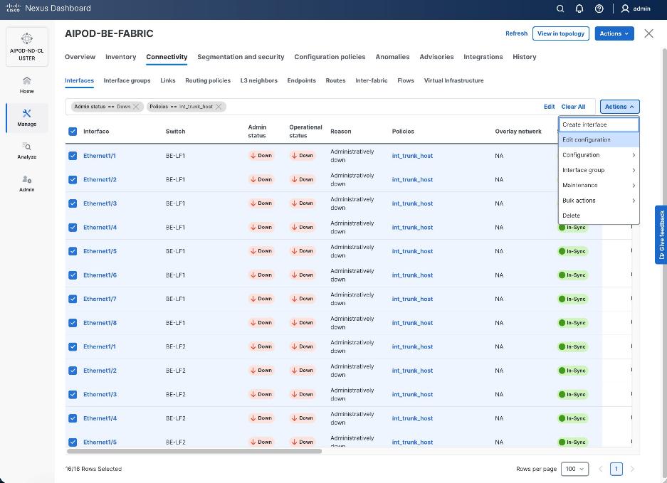
Step 4. Configure the first port going in the above list.
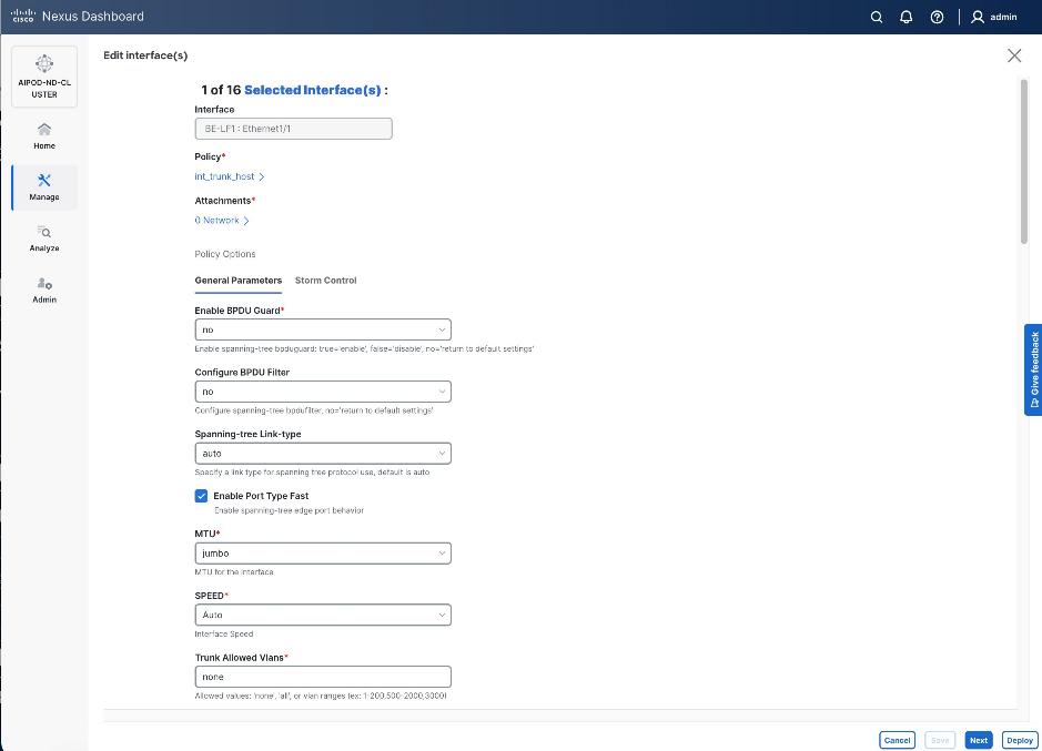
Step 5. Click int_trunk_host under Policy. In the Select Attached Policy Template pop-up window, select int_access_host from the drop-down list.
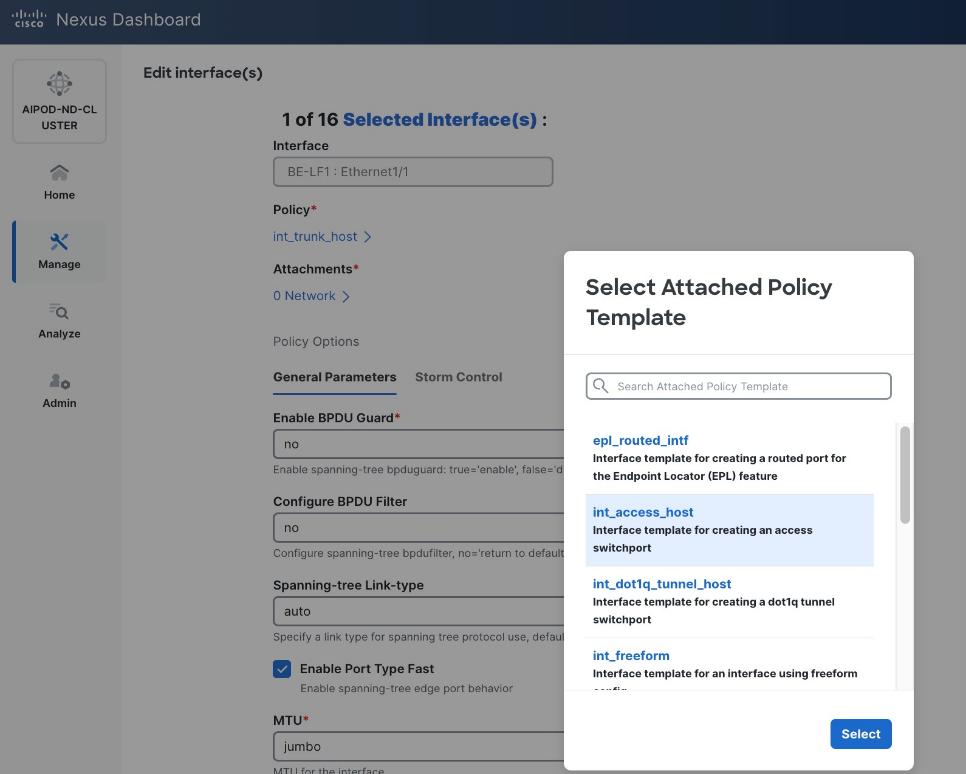
Step 6. Click Select.
Step 7. Make any other changes as needed. Click Save and click Next until all ports have been configured.
Step 8. Click Save.
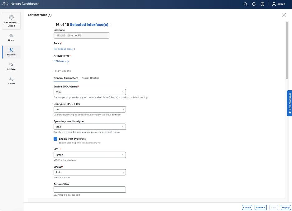
Step 9. Click Deploy.
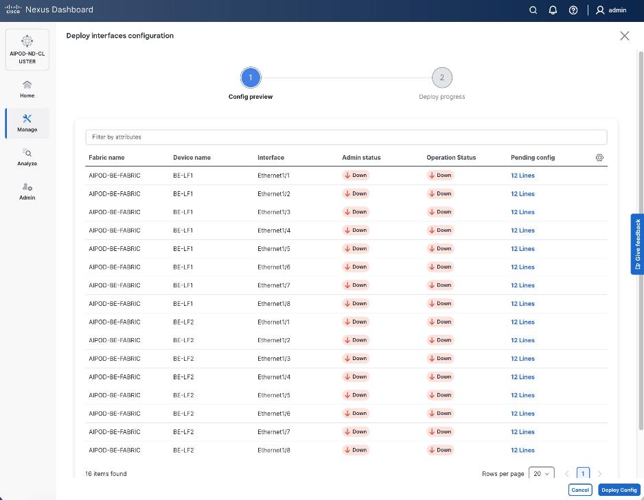
Step 10. Click the line count for each port in the Pending Config column to see the configuration being deployed.
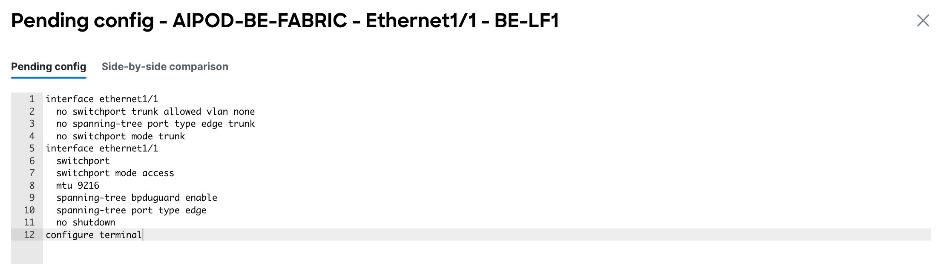
Step 11. Click Close.
Step 12. Click Deploy Config.
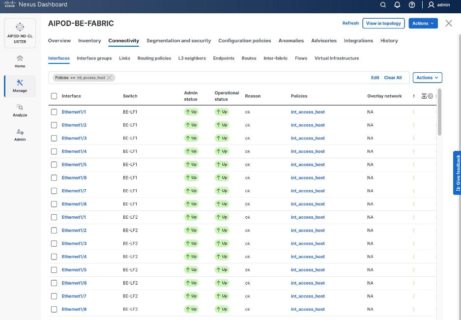
Procedure 2. Deploy L2 overlay network in the BE fabric for inter-node UCS connectivity
Step 1. From a web browser go to the Nexus Dashboard. Use the management IP of any node in the ND cluster. Log in using admin account.
Step 2. From the navigation menu, go to Manage > Fabrics.
Step 3. Select the BE Fabric from the list and click the BE fabric name.
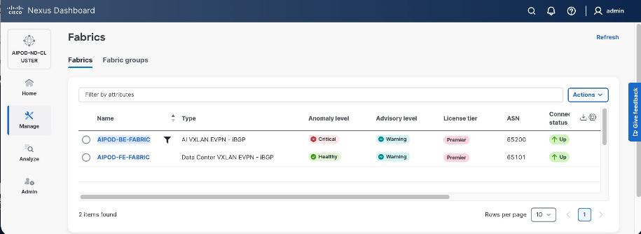
Step 4. Go to the Segmentation and Security > Networks tab. To deploy the BE network on UCS nodes, click the lower Actions button and select Create from the drop-down list.
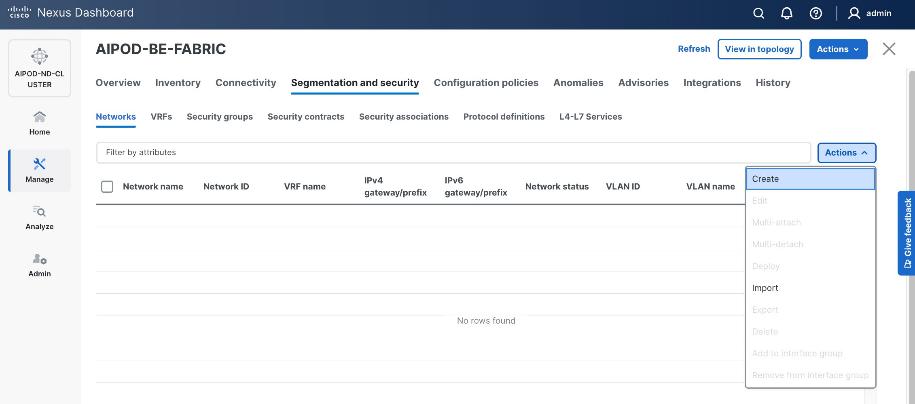
Step 5. In the Create Network window, specify the following:
● Network name.
● Enable checkbox for Layer 2 only or VRF name if it is a Layer 3 network.
● Network ID (or use default).
● VLAN ID (or use Propose VLAN for system to allocate).
● For a Layer 3 network, if VRF hasn't been created already, you have an option from this window to also create a VRF (click Create VRF).
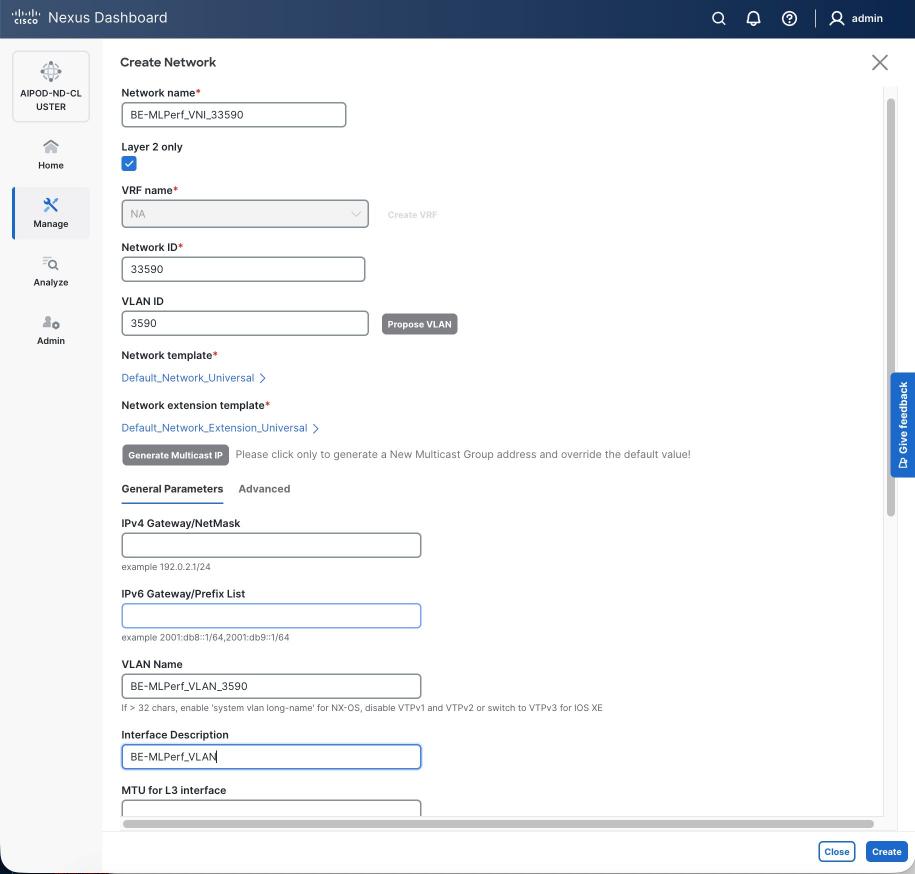
Step 6. Click Create to create the Layer 2 overlay network.
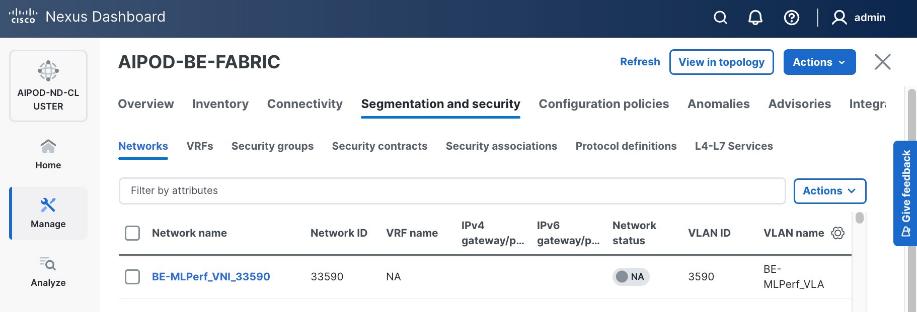
Step 7. Select the newly created network and deploy it on both leaf pairs. Click the lower Actions button and select Multi-attach from the list.
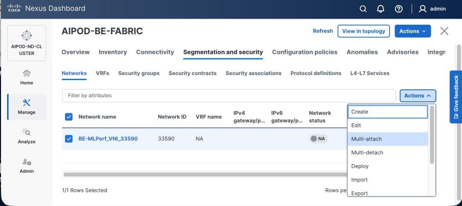
Step 8. Select both BE Leaf Switches.
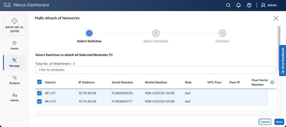
Step 9. Click Next. Select the row for the first switch and click Select Interfaces to select the interfaces going to the UCS C885A nodes on that switch.
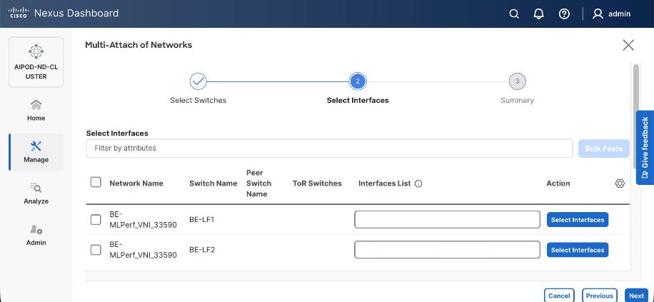
Step 10. Select all ports on the first switch that connect to UCS GPU nodes.
Step 11. Click Save.
Step 12. Repeat steps 1 – 11 for the second leaf switch to select the ports going to the UCS GPU nodes on that switch. (Repeat for any remaining leaf switches if you have more than two).
Step 13. Click Next.
Step 14. Click Save.
Note: Pending configuration being deployed on leaf switches is included at the end as a reference.
Step 15. Click Deploy All.
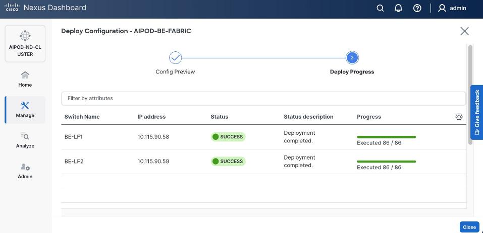
Step 16. Click Close.
Step 17. Click the network name and verify status is deployed.
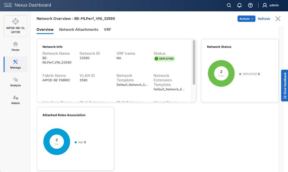
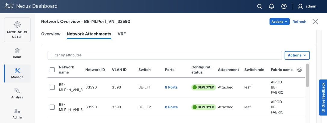
Step 18. Click the X in the top right corner to close this window.
Step 19. Filter the newly deployed network 16 ports. Verify the status of all ports.
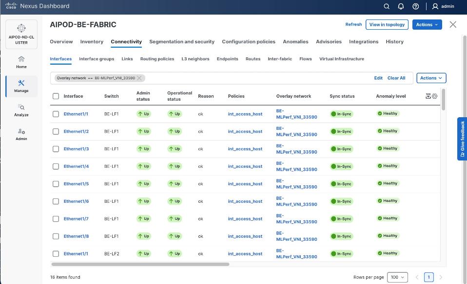
Step 20. Verify that ports on both switches are Up with an In-Sync status.
VAST Data Cluster Configuration
This chapter contains the following:
Claim EBox Nodes on Cisco Intersight
Create UCS Server Profile Template
Derive and Deploy UCS Server Profile
VAST Cluster Initial Setup and Validation
This chapter describes the step-by-step procedures to configure VAST Data Cluster on Cisco EBox nodes built upon the Cisco UCS C225 M8 platform. The VAST Data EBox nodes are configured in Intersight Standalone Mode (ISM).
The process flow illustrated below elaborates on the high-level steps to configure Cisco UCS C225 M8 server and install operating system:
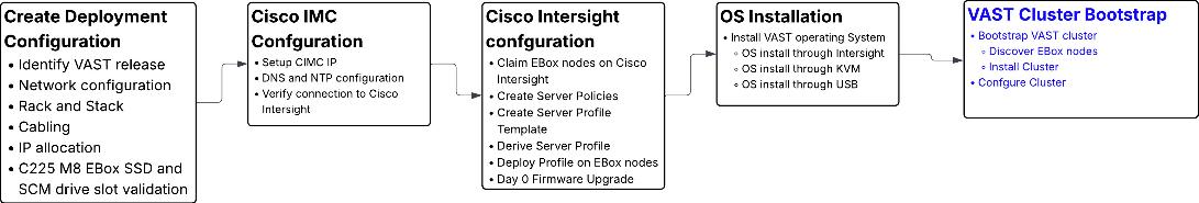
Note: VAST Cluster bootstrap (marked in blue) are a high level illustration and not part of this document. VAST Cluster installation should always be executed under VAST SME guidance
Note: CIMC IP configuration requires local access to the server nodes.
Procedure 1. Configure CIMC IP
Step 1. Connect a USB keyboard and VGA monitor to the server using one of the following methods:
● Connect an optional KVM cable (Cisco PID N20-BKVM) to the KVM connector on the front panel. Connect your USB keyboard and VGA monitor to the KVM cable.
Or
● Connect a USB keyboard and VGA monitor to the corresponding connectors on the rear panel.
Step 2. Power On the Server.
Step 3. During bootup, press F8 when prompted to open the Cisco IMC Configuration Utility.
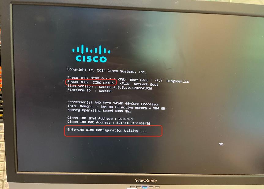
Step 4. The first time that you enter the Cisco IMC Configuration Utility, you are prompted to change the default password. The default password is password. The Strong Password feature is enabled. Setup the password and press Enter.
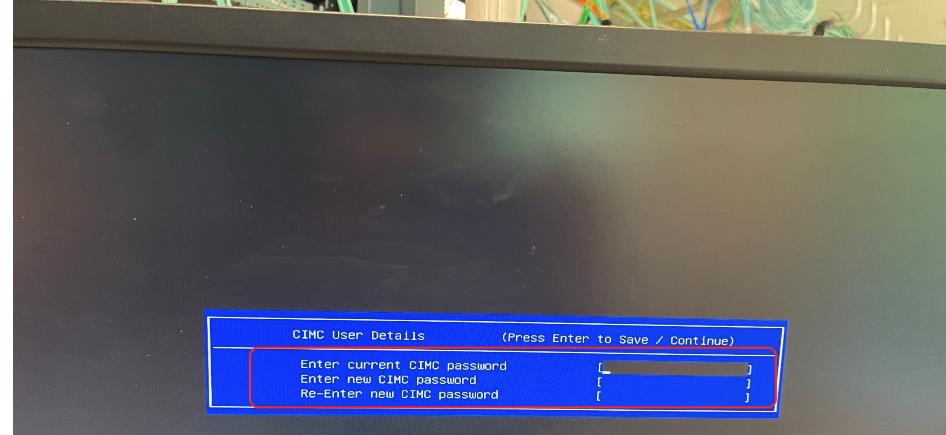
Step 5. From the Cisco IMC Configuration utility, edit the following details. The details are also displayed the screenshot below with edits marked in red.
● NIC mode to dedicated.
● Select IP (Basic) configuration.
Note: This CIMC IP should be taken from IP configuration table created in Cabling and IP configuration sheet
● Enter CIMC IP, prefix, gateway and Preferred DNS Server.
● Select NIC redundancy to none.
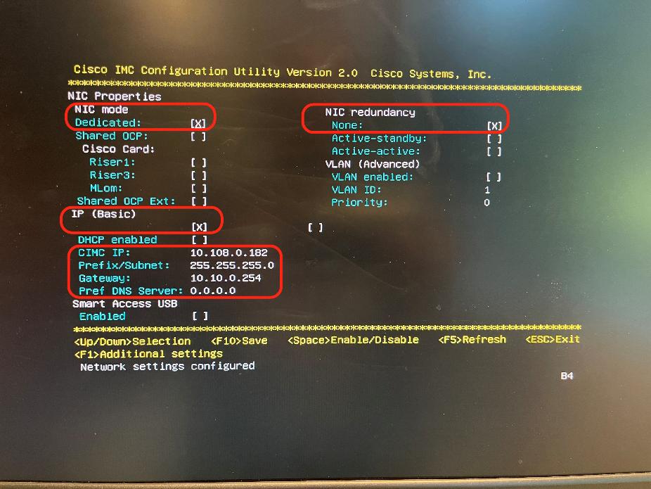
Step 6. Press F10 to save the configuration and exist During bootup, press F8 when prompted to open the Cisco IMC Configuration Utility.
Step 7. When the configuration is saved, press ESC to exit the screen.
Claim EBox Nodes on Cisco Intersight
This procedure details how to claim Cisco UCS C225 M8 nodes on Cisco Intersight.
Procedure 1. Claim EBox Nodes on Cisco Intersight
Note: This procedure requires local access to the server nodes.
Step 1. Log into Cisco Intersight account. If this is the first time, create a Cisco Intersight Account. For detailed steps, see: Cisco Intersight Account Creation.
Step 2. Open a web browser and enter Cisco IMC IP, log in with the username: admin and the password as configured during CIMC configuration process.
Step 3. From the drop-down list, select Dashboard > Administration.
Step 4. From the navigation pane, click Device Connector and verify the connection of the node to Cisco Intersight. As shown below, you need to update the DNS and NTP configuration to successfully resolve Intersight domain name.
Step 5. Click open settings and update NTP and DNS servers.
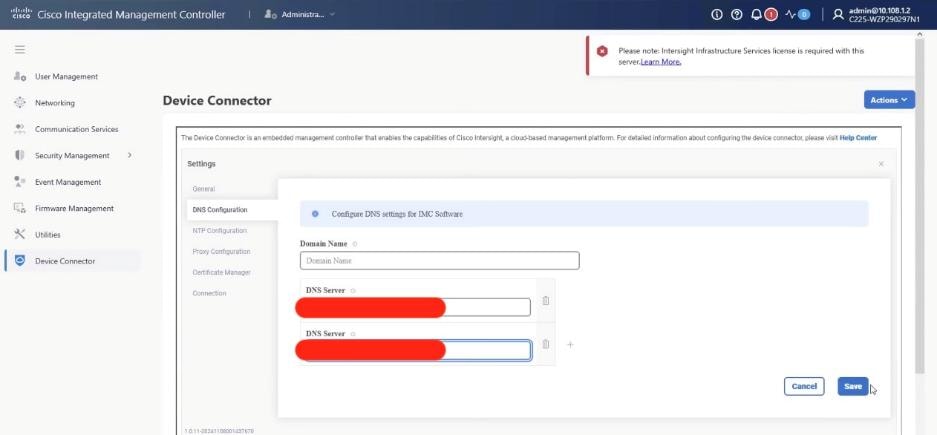
Step 6. Ensure the server is not already claimed, copy the Device ID and Claim Code which is used to claim the server on Cisco Intersight.
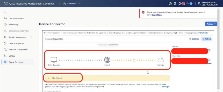
Step 7. Log into Cisco Intersight, go to System > Targets.
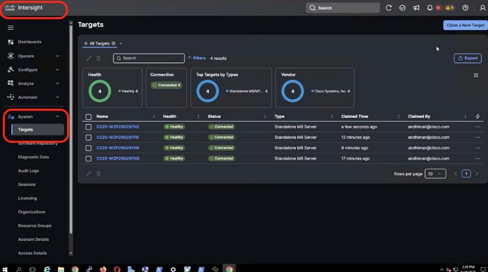
Step 8. Click Clain New Target.
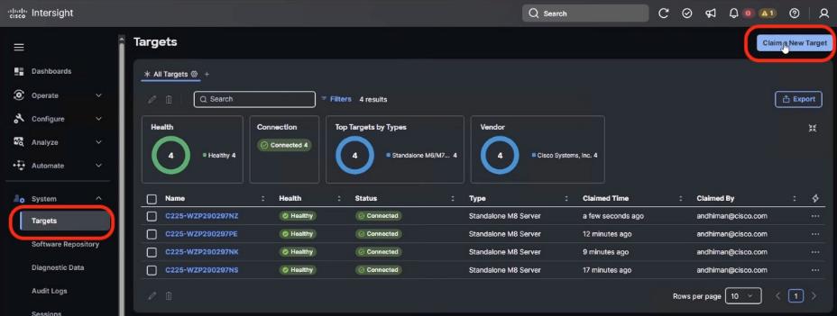
Step 9. From Select Target Type, select Cisco UCS Server (Standalone) and click Start.
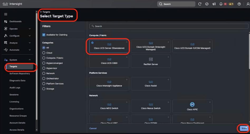
Step 10. From Claim a new Target, enter the Device ID and Claim Code from Cisco IMC. Click Claim.

Step 11. Cisco Intersight starts the claim process of the Cisco UCS C225 M8 node. Ensure the server serial number is listed in the Target screen.
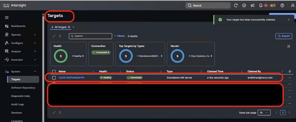
Step 12. Repeat steps 1 -11 to claim all the servers on Cisco Intersight.
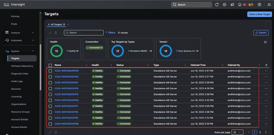
Cisco Intersight server policies are used to define and manage the configuration of Cisco UCS servers, both in Intersight Managed Mode (IMM) and Intersight Standalone Mode (ISM). These policies cover various aspects like BIOS settings, local disk configurations, boot security, and maintenance windows. They ensure consistency, efficiency, and flexibility in server management by allowing administrators to apply predefined configurations across multiple servers.
The following is the list of Server Policies to enable VAST Data cluster on Cisco UCS C225 M8 node:
● Compute policies:
◦ Basic input/output system (BIOS)
◦ Boot Order
◦ Power
◦ Storage policy to define the RAID1 configuration on M.2 Boot SSD
● Management Policies:
◦ IPMI over LAN
◦ Serial over LAN
◦ Local User – enables IPMI username password. Once configured , same username password would be used to access KVM and local Cisco IMC Dashboard
◦ Virtual KVM – enables tunned/remote access to KVM of each VAST cluster node
Procedure 1. Create BIOS Policy
Tabe 21 lists the required configuration for the BIOS policy.
Table 21. BIOS settings for VAST Data on Cisco UCS C225 M8 nodes
|
|
Option |
Setting |
| Boot Options |
IPV4 HTTP Support |
disabled |
| IPV6 HTTP Support |
disabled |
|
| IPV6 PXE Support |
disabled |
|
| Processor |
Local APIC Mode |
X2APIC |
| PCI |
|
enabled |
| Server Management |
Console Redirection |
COM0 |
Step 1. Go to the Cisco Intersight Dashboard and click Configure > Policies. Click Create Policy.
Step 2. From Select Policy Type, select UCS Server and BIOS. Click Start.
Step 3. Enter name of the Policy and click Next.
Step 4. From Policy detail, select the UCS Server (Standalone) tab. Select the BIOS options as listed in Table 21. The BIOS policy attribute selection are detailed below. Click Create.
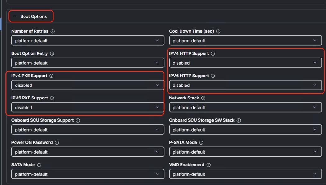
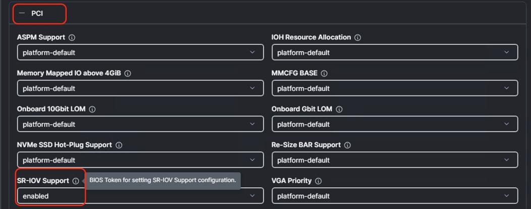
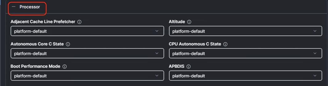
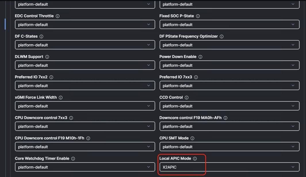
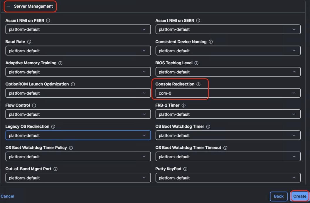
Procedure 2. Create Storage Policy
Note: The Storage Policy enables RAID1 across 2x M.2 Boot drives.
Step 1. Go to the Cisco Intersight Dashboard and click Configure > Policies. Click Create Policy.
Step 2. Select UCS Server > Storage option and click Start.
Step 3. Add a name to the Storage Policy and click Next.
Step 4. Select UCS Server (Standalone), enable M.1 RAID Configuration. MSTOR-RAID is selected by default for Slot of the M.2 RAID controller. Click Create.

Procedure 3. Create Boot Order Policy
Note: The Boot Order Policy enables boot for the RAID1 virtual drive created on 2x M.2 cards and virtual media mount point.
Step 1. Go to the Cisco Intersight Dashboard and click Configure > Policies. Click Create Policy.
Step 2. Select UCS Server > Boot Order and click Start.
Step 3. Add a name to the Boot Order Policy and click Next.
Step 4. Under Policy details:
● Select the UCS Server (Standalone) option.
● Add virtual media (vmedia) as boot device and name the device as vmedia1 or any name as per your naming convention.
● Add another boot target as local disk. Name the boto target device as local-disk-boot or any name as per your naming convention. In the Slot field, enter MSTOR-RAID as shown below.
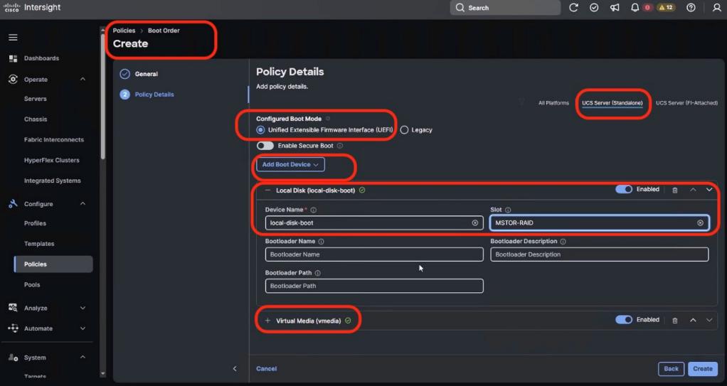
Step 5. Ensure the first boto target is Local Disk and the Slot for Local Disk is MSTOR-RAID.
Step 6. Click Create.
Procedure 4. Create Power Policy
Step 1. Go to the Cisco Intersight Dashboard and click Configure > Policies. Click Create Policy.
Step 2. Select UCS Server > Power and click Start.
Step 3. Add a name to the Power Policy and click Next.
Step 4. From the Policy detail screen, select UCS Server (Standalone) and Power Restore Policy as Always On and Processor Package Power Limit (PPL) as Maximum.
Step 5. Click Create.
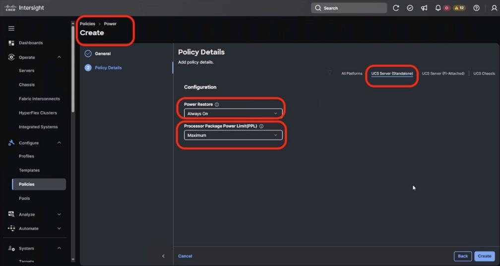
Procedure 5. Create IPMI over LAN Policy
Step 1. Go to the Cisco Intersight Dashboard and click Configure > Policies. Click Create Policy.
Step 2. Select UCS Server > IPMI over LAN and click Start.
Step 3. Add a name to the Policy and click Next.
Step 4. From the Policy detail screen, select UCS Server (Standalone), ensure Privilege Level is admin and click Create.
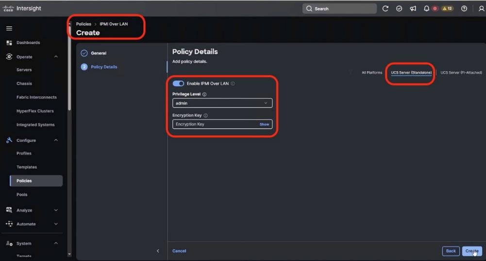
Step 5. Click Create.
Procedure 6. Create Local User Policy
Step 1. Go to the Cisco Intersight Dashboard and click Configure > Policies. Click Create Policy.
Step 2. Select UCS Server > Local User and click Start.
Step 3. Add a name to the Policy and click Next.
Step 4. From the Policy detail screen, select UCS Server (Standalone):
● Disable Enforce Strong Password
● Change the Password History to 0 (password never expires)
● Add a New user with username admin, Role admin and password as adminvastdata
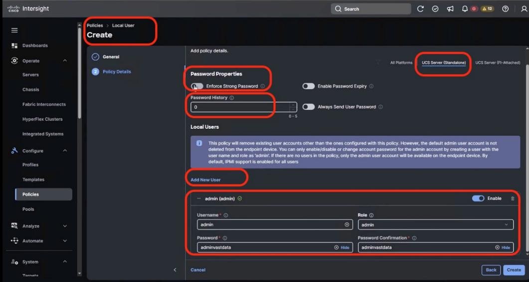
Step 5. Click Create.
Note: During initial deployment, the password should be kept as adminvastdata with Role admin. You can change access the KVM and CIMC local dashboard through this username and password
Note: The same username password is used for VAST IPMI access of nodes. In the event you change the IPMI password through VAST cluster, you should ensure to change the admin password for local user through the User Policy.
Procedure 7. Create Serial Over LAN Policy
Step 1. Go to the Cisco Intersight Dashboard and click Configure > Policies. Click Create Policy.
Step 2. Select UCS Server > Serial Over LAN and click Start.
Step 3. Add a name to the Policy and click Next.
Step 4. From the Policy detail screen, select UCS Server (Standalone), and ensure default selected is:
● COM Port as com0
● Baud Rate as 115200
● SSH Port as 2400
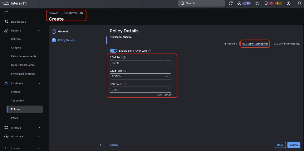
Step 5. Click Create.
Procedure 8. Create Virtual KVM Policy
Step 1. Go to the Cisco Intersight Dashboard and click Configure > Policies. Click Create Policy.
Step 2. Select UCS Server > Virtual KVM and click Start.
Step 3. Add a name to the Policy and click Next.
Step 4. From the Policy detail screen, select UCS Server (Standalone), and enable Allow Tunneled vKVM.
Step 5. Click Create.
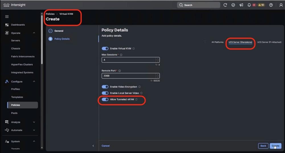
Create UCS Server Profile Template
A server profile template enables resource management by simplifying policy alignment and server configuration. All the policies created in previous section would be attached to Server Profile Template. You can derive Server Profiles from templates and attach to Cisco UCS C-Series nodes for VAST Data. For more information, go to: https://www.intersight.com/help/saas/features/servers/configure#server_profiles.
Table 22. Policies required for Server profile template
| Compute Policies |
Storage Policies |
Management Policies |
| BIOS Policy |
RAID1 for 2x M.2 Boot card |
IPMI Over LAN Policy |
| Boot Order Policy |
|
Local User Policy |
| Power Policy |
|
Serial Over LAN Policy |
| Virtual KVM Policy |
The following screenshot displays all the seven Sever Policies created to create Server Profile Template for VAST Data nodes:
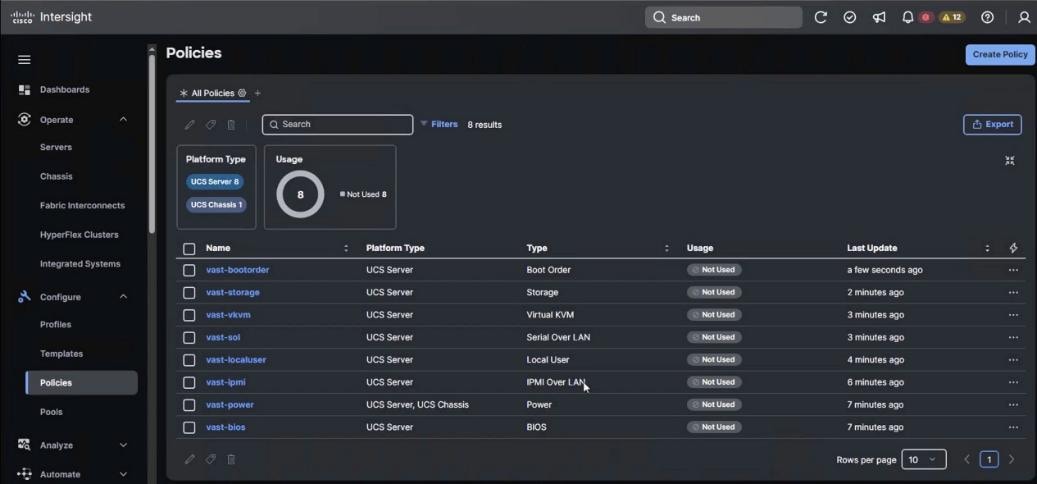
Procedure 1. Create UCS Server Profile Template
Step 1. From the navigation pane, select Configure > Templates > UCS Server Profile Template and click Create UCS Server Profile Template.
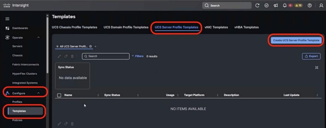
Step 2. Name the Server Profile Template, select Target Platform as UCS Server (Standalone) and click Next.
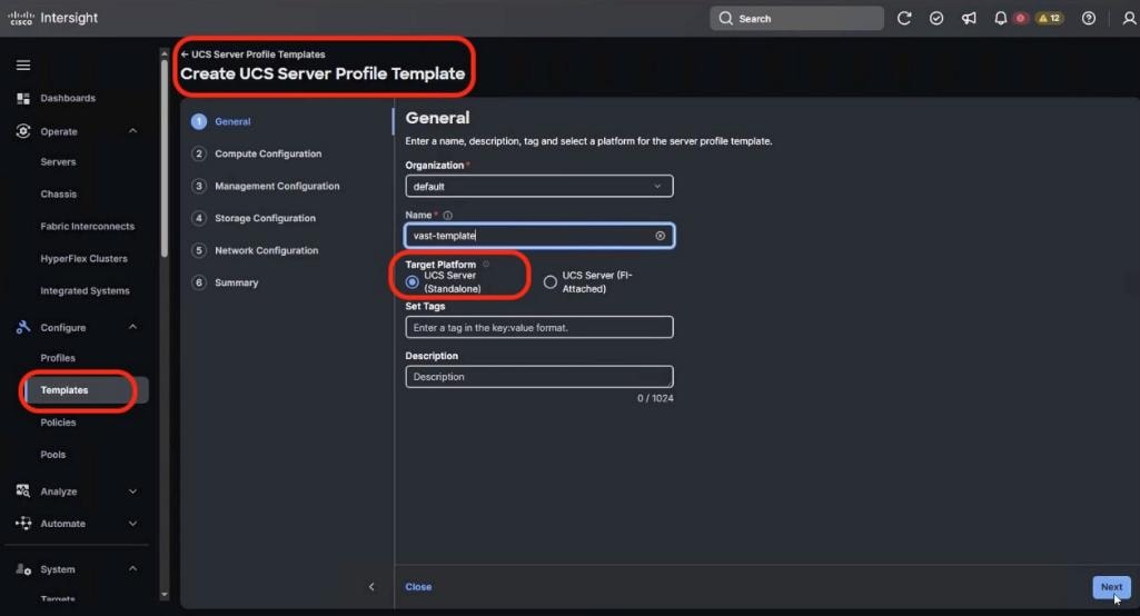
Step 3. From the Compute Configuration section, select the previously created policies as detailed below:
● BIOS Policy
● Boot Order Policy
● Power Policy
Step 4. Click Next.
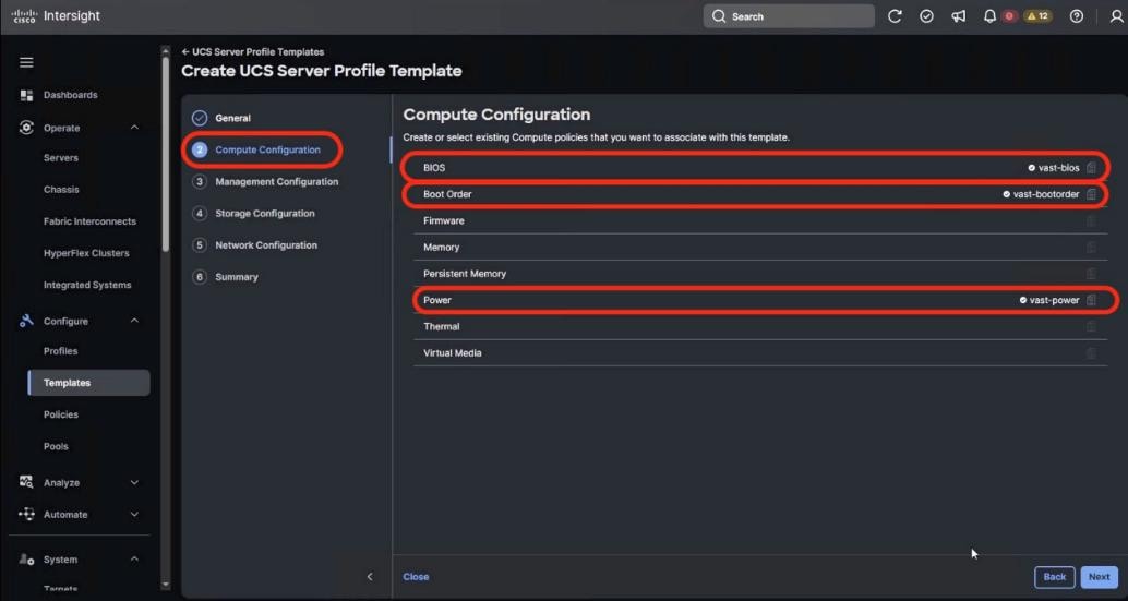
Step 5. From the Management Configuration section, select the previously created policies as detailed below:
● IPMI Over LAN Policy
● Local User Policy
● Serial Over LAN Policy
● Virtual KVM Policy
Step 6. Click Next.
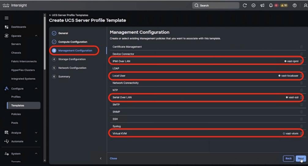
Step 7. From the Storage Configuration section, select the previously created Storage Policy as detailed below, then click Next.
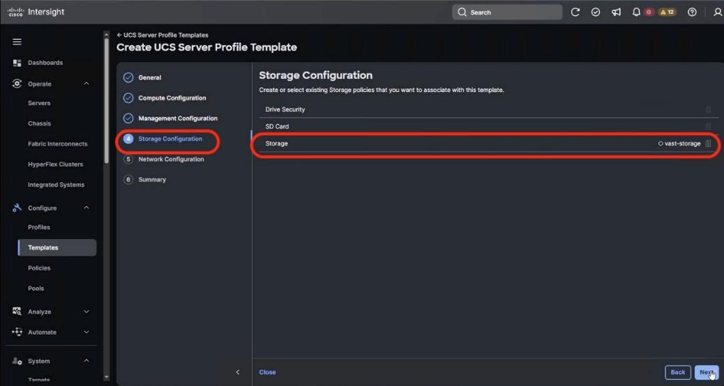
Step 8. No Server Policies are selected in Network Configuration section. Click Next.
Step 9. Verify the Server Profile Template Summary (Compute, Management and Storage Configuration) and click Close.
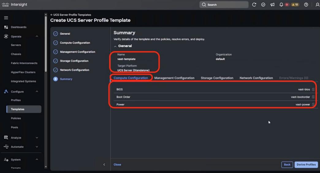
Derive and Deploy UCS Server Profile
In this procedure, the Server Profiles are derived from Server Profile Template and deployed on Cisco UCS C-Series nodes certified for the VAST Data.
Note: The Server Profile Template specific to the VAST Cluster was configured in the previous section.
Procedure 1. Derive and deploy UCS Server Profile
Step 1. Select Configure > UCS Server Profile Template and identify the VAST Server Profile Template created.
Step 2. Click the ellipses and select Derive Profiles.
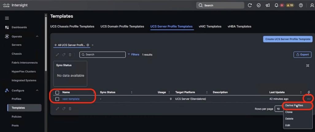
Step 3. Select all the Cisco UCS C225 M8 nodes which are claimed to create VAST cluster. Ensure the Assign Now option is selected by default. Click Next.
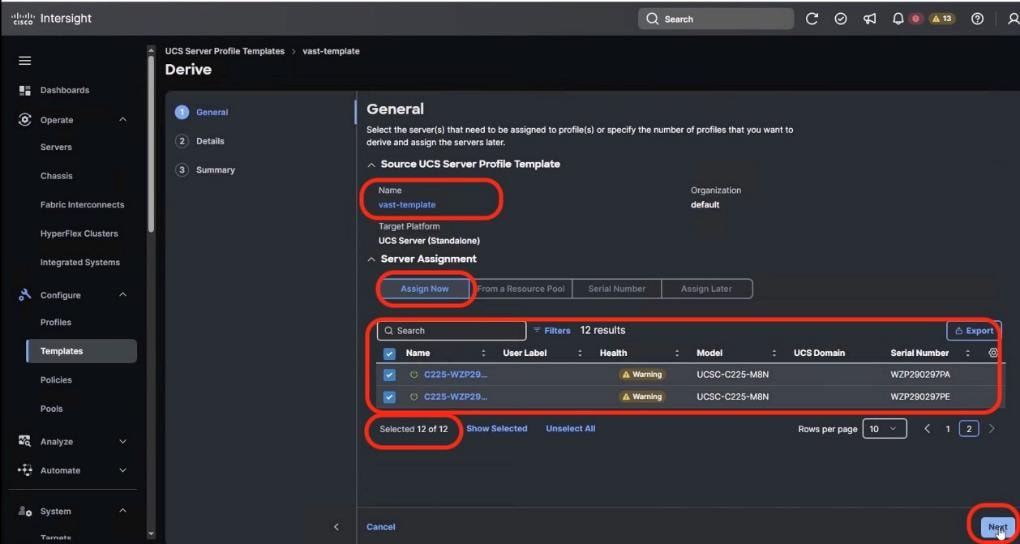
Step 4. Edit the Server Profile Name prefix and click Next.
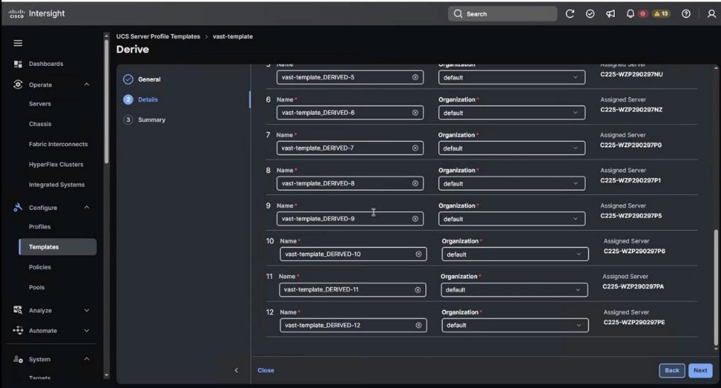
Step 5. In the summary section, ensure all the Server Policies are part of the template and click Derive.
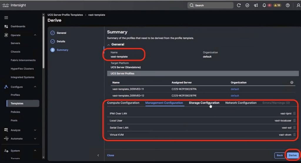
Step 6. From the navigation pane, go to Profiles > UCS Server Profiles. Ensure Profiles are attached to UCS C225 M8 server nodes and are in Not Deployed state.
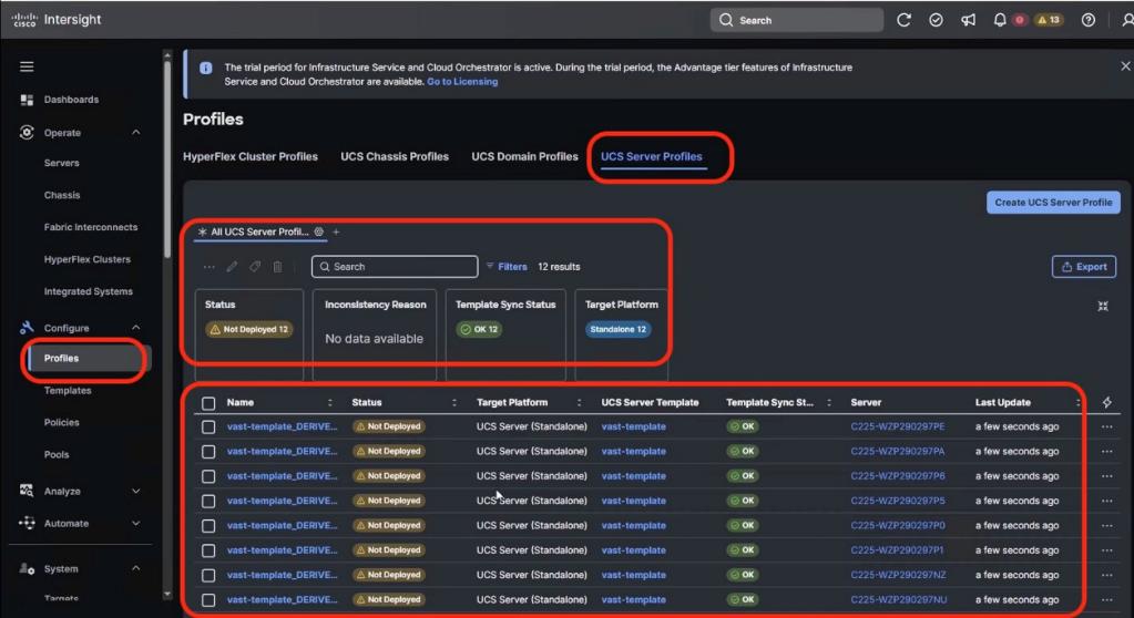
Step 7. To select all profiles, select the Name checkbox and click the ellipses and select Deploy.
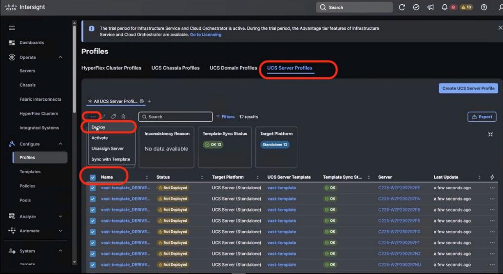
Step 8. Select Reboot immediately and warning for potential disruption and select Deploy. Click the ellipses and select Derive Profiles. The Server Profiles deploy on each of UCS C225 node with the policy driven state applicable for VAST nodes on UCS C225 M8 servers.
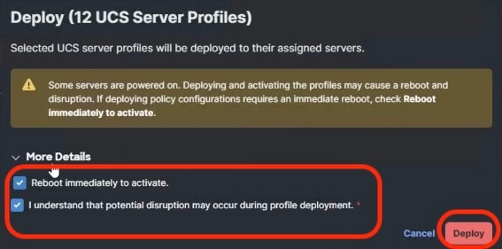
Note: The process enables validation, deployment, and activation of the Server Profiles on each UCS C225 M8 node. Each node is rebooted. This process may take around 15 to 20 minutes.
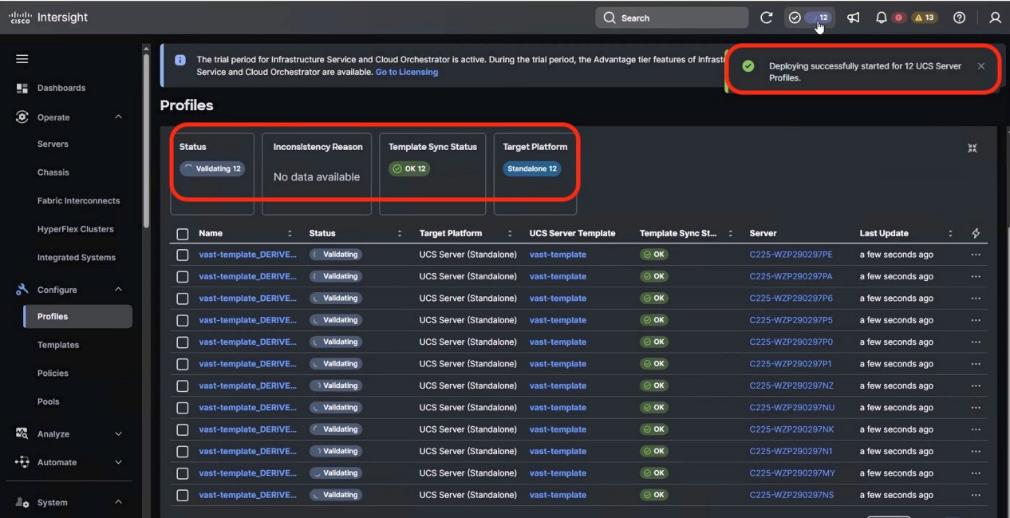
Step 9. Monitor the execution flow and progress of Server Profile deployment:
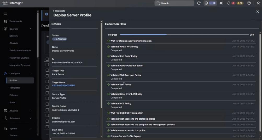
Note: The process enables validation, deployment and activation of the Server Profiles on each UCS C225 M8 node. Each node is rebooted. This process may take around 15 to 20 minutes.
Step 10. Go to Operate > Servers and ensure the Server Profile is deployed successfully.
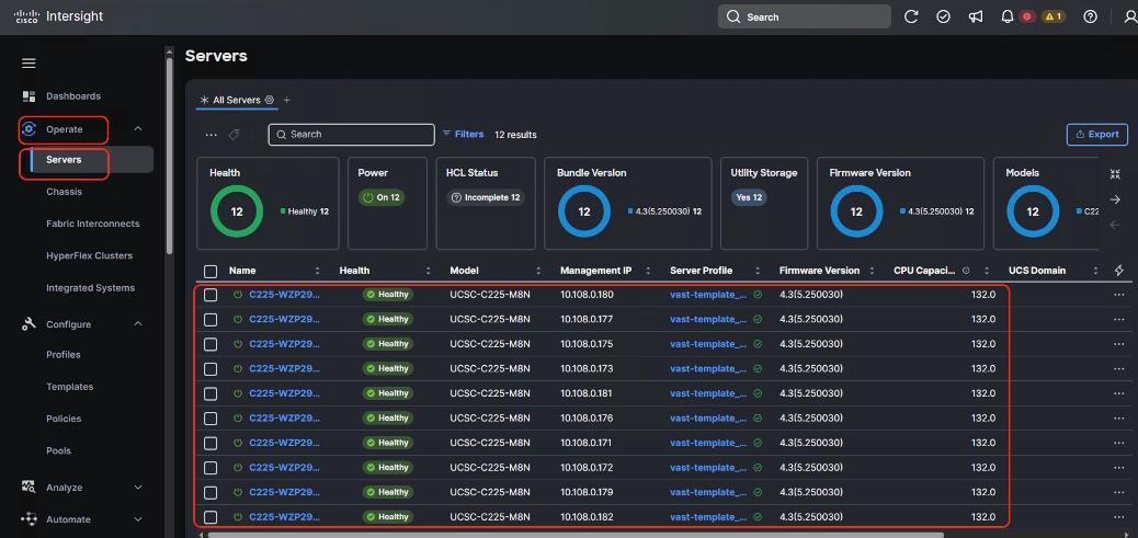
Prior to installing VAST software, it is highly recommended to upgrade the Cisco UCS C225 M8 server firmware to the recommended Cisco UCS C-Series Firmware release.
Day 0 node firmware upgrade can be executed parallelly across all the server nodes. Intersight firmware upgrades for servers in Standalone mode or for servers deployed for VAST are streamlined through the Intersight platform. This process involves selecting the device, choosing the target firmware, and initiating the upgrade.
Note: This procedure should only be initiated during first time node configuration. It could be also used for cluster expansion or during replacement of cluster node
Note: You should identify the correct firmware version through VAST support or VAST installation SME.
Procedure 1. Upgrade the Day 0 EBox firmware
Step 1. Identify the Cisco C225 M8 firmware validated for VAST. At the time of writing this install guide the validated firmware Version was 4.3(5.250030)
Step 2. From the navigation pane, go to Operate > Servers. Select the servers which are either part of new cluster, or which are being added to an existing cluster.
Step 3. Select the Servers checkbox.
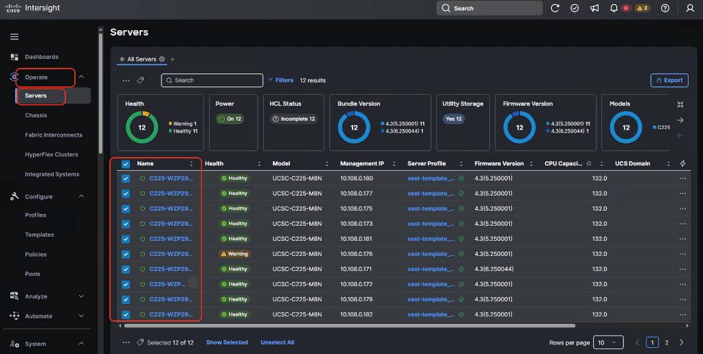
Step 4. Click the ellipses and select Upgrade Firmware.
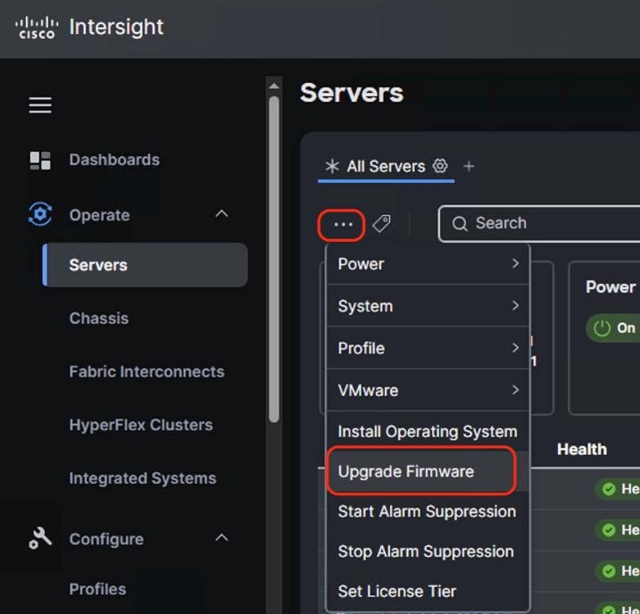
Step 5. Select start and click Next. In the General options, ensure UCS C225 M8 nodes are selected.
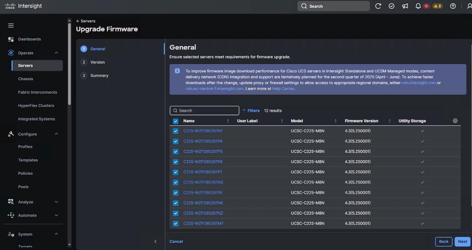
Step 6. Select the firmware version for the group of UCS C225 M8 nodes.
Note: By default, the storage controller and drive firmware is upgraded. The Advanced Mode enables you to deselect the firmware upgrade for storage controller and drive firmware.
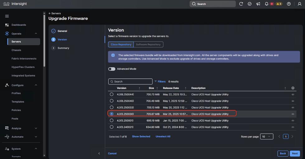
Step 7. Verify the Firmware upgrade summary. The selected firmware will be downloaded on local utility storage of each of the server end points. Once the download complete the firmware upgrade workflow will be executed. Click Upgrade.
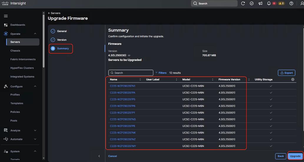
Step 8. In the Upgrade Firmware popup, confirm firmware upgrade and click Upgrade.
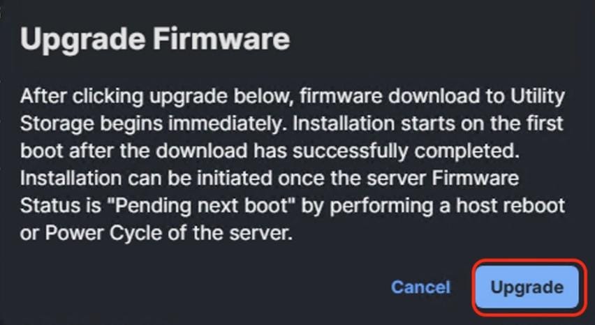
Step 9. When the firmware is downloaded and staged locally to utility storage of each server end point. Acknowledge server reboot and wait for Server Firmware to upgrade successfully.
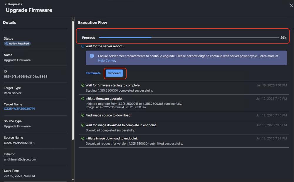
Step 10. Verify successful Server Firmware upgrade to 4.2(5.250030) across all the nodes.
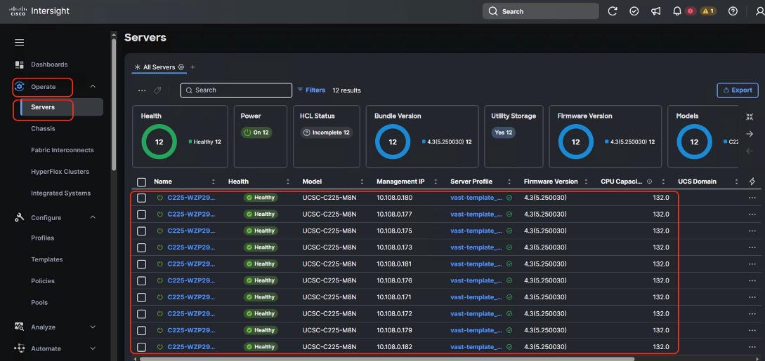
Note: You should identify the correct firmware version either through Installation team or through VAST support.
The base OS installation occurs prior to the VAST cluster bootstrap process is executed through one of three ways:
1. OS installation through Cisco Intersight
2. OS installation through KVM
3. OS installation through USB drive
This section details a step-by-step procedure to install the base OS through Cisco Intersight and KVM. Both procedures require a local copy of VAST operating System.
Note: Identify the correct base operating system version to be installed on UCS C225 M8 servers for VAST. At the time of creating this install guide, the available VAST OS version was vast-os-12.14.17-1818066.
Note: This procedure can be executed either only on UCS C225 M8 nodes during new VAST cluster setup or for additional nodes for expansion of an existing cluster.
Procedure 1. Install VAST OS through Cisco Intersight OS Installation feature
This procedure details the process to install the VAST operating system through the Cisco Intersight OS installation feature.
Note: Before proceeding to installing VAST OS through Intersight Install feature, please ensure virtual media (vmedia) has the lowest priority in the Boot Order policy as shown below:
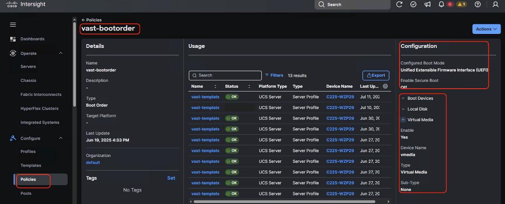
Note: This feature is only supported with the Intersight Advantage Tier License.
Note: Make sure the VAST operating system ISO is available from a local repository, for example an HTTPS/NFS/CIFS server. This is a one-time process for each version of the VAST OS ISO.
Step 1. Log into Cisco Intersight and click System.
Step 2. Click Software Repository and click the OS Image Links tab.
Step 3. Click Add OS Image Link.
Step 4. Add the location of VAST operating system ISO (NFS/CIFS or HTTPS server) and click Next.
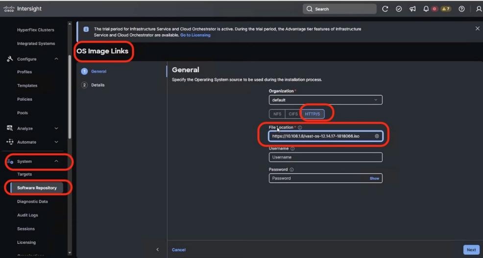
Step 5. Enter a name for the Repository, for the Vendor enter Rocky Linux, and for the Version enter Rocky Linux 8.6. Click Add.
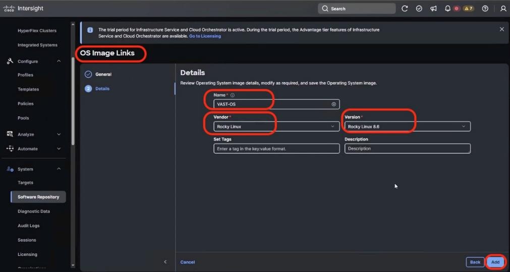
Step 6. Verify that the OS Repository is successfully created in Cisco Intersight.
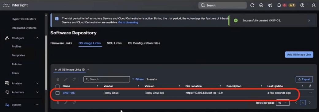
Step 7. From the navigation pane, click Operate>Servers and select the Cisco UCS C-Series nodes ready for the OS deployment.
Step 8. Click the ellipses and select Install Operating System.
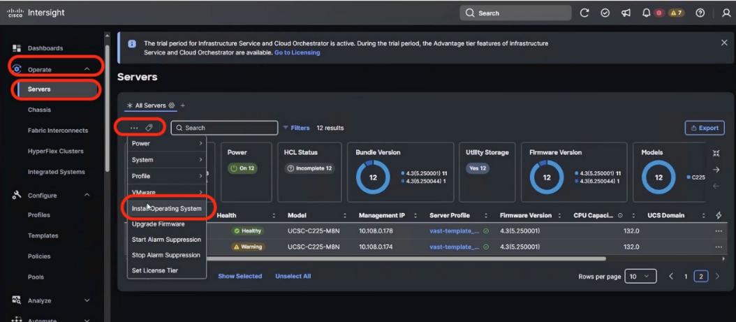
Step 9. Make sure the servers are already selected and click Next.
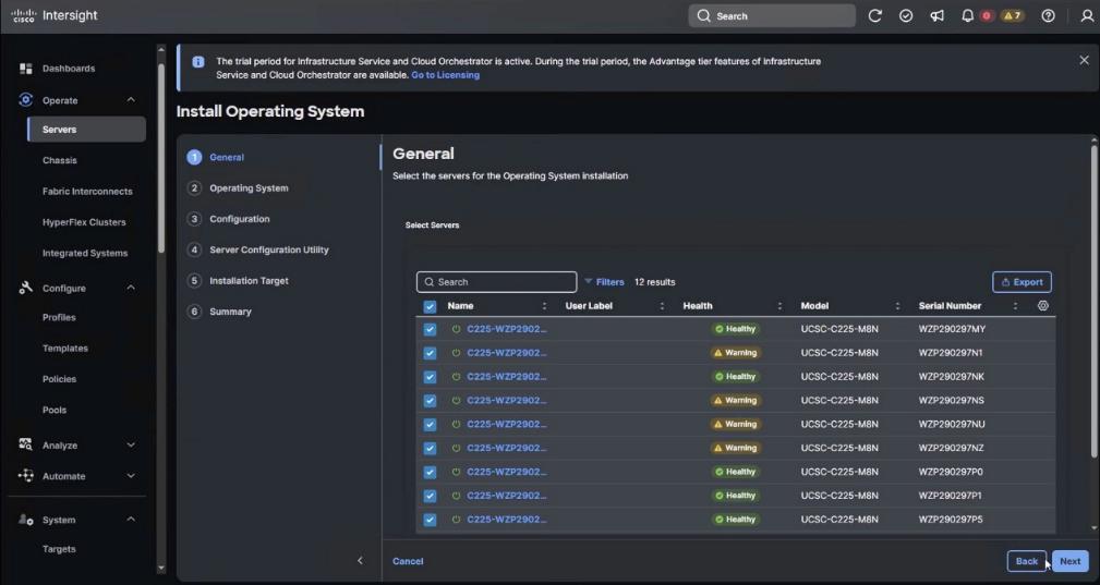
Step 10. Select the Operating System repository which was previously created with the VAST operating system ISO and click Next.
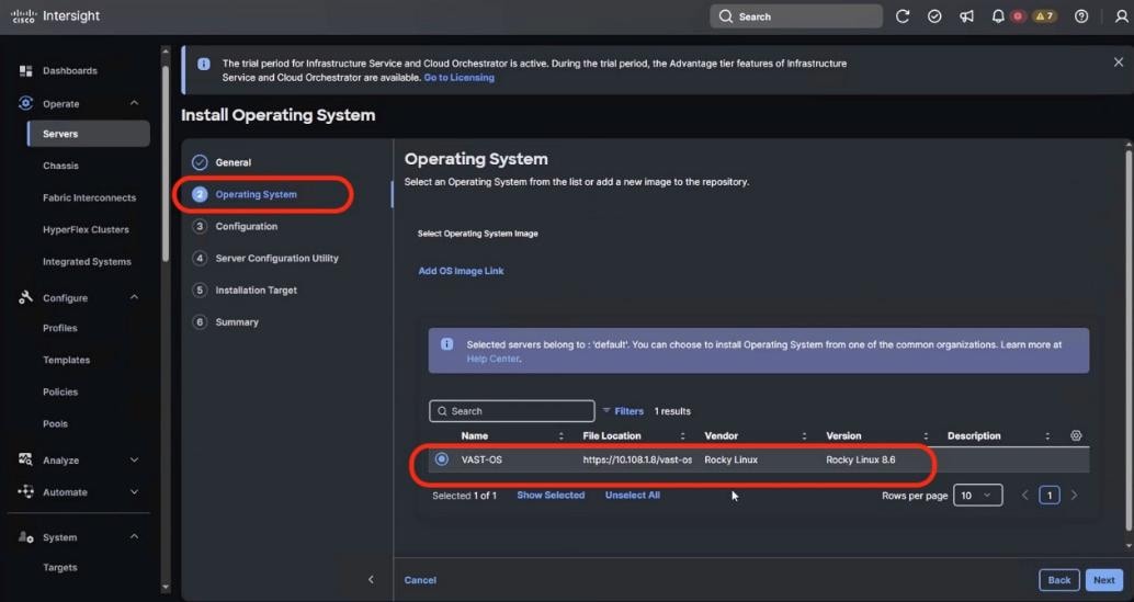
Step 11. From Configuration, click Embedded and click Next (the OS configuration file is already part of VAST ISO).
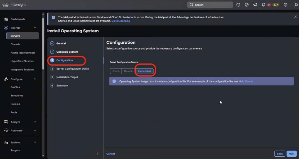
Step 12. Click Next. No SCU Link is required.
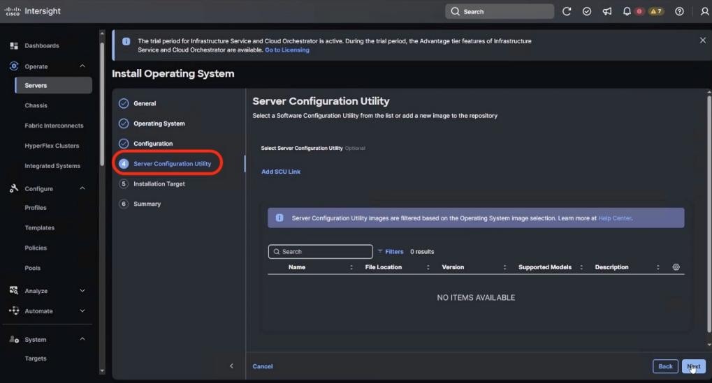
Step 13. Click Next. In the Installation target screen. VAST ISO automatically identifies the Installation target as the RAID1 virtual drive on 2x M.2 internal drives configured in the Boot Order Server Policy.
Step 14. Verify the summary and click Install.
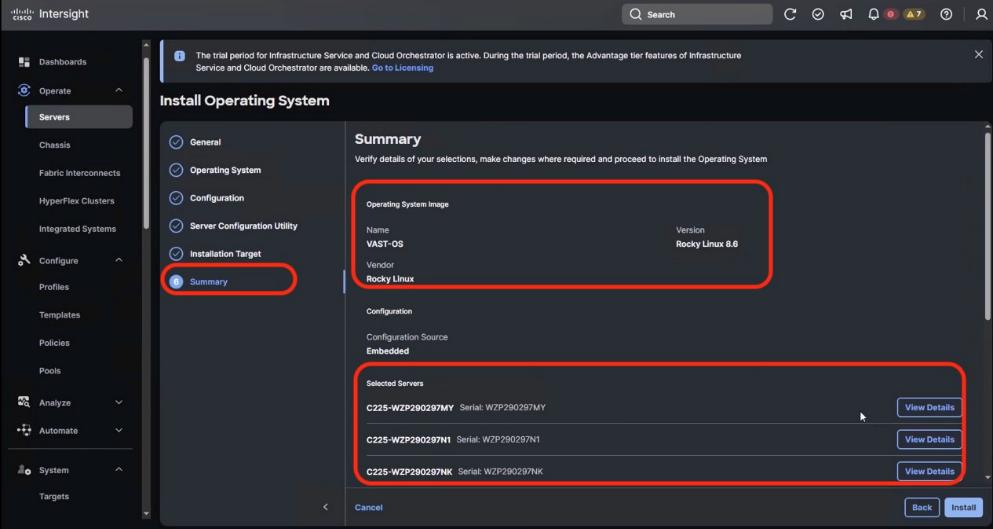
Step 15. Accept the warning for overwriting the existing OS image on the node and click Install.
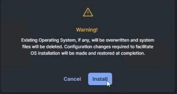
Step 16. Monitor the OS installation progress and wait for completion. Depending on the network bandwidth between the node management network and the repository network, it can take up to 20 to 30 minutes for the OS installation to complete.
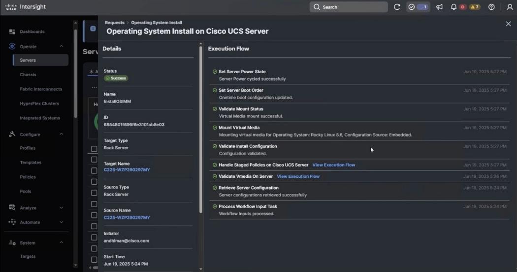
Step 17. Since this is an embedded installation without the Cisco Server Configuration utility, Cisco Intersight displays the OS installation completion in about five minutes. Open a virtual KVM session and monitor the OS install progress. Since this is an automated install, you are not required to provide any inputs on the virtual KVM screen. The OS installation progress is shown below:
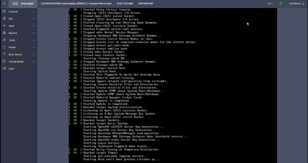
Step 18. Ensure OS is successfully installed on Cisco UCS C-Series nodes. Log in with vastdata/vastdata to verify successful OS installation.
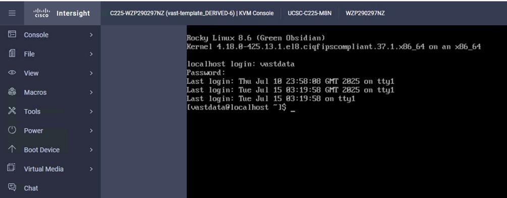
Procedure 2. Install the VAST OS through virtual media
This procedure details the process to install the operating system through virtual media. You need to open a virtual KVM session for each node. Virtual KVM session can be accessed through Cisco Intersight or logging into node CIMC IP. During the OS installation, it is recommended to open vKVM through node CIMC IP. Access the vKVM through the user created in Local User policy (admin/<<password>>)
Step 1. Log into Intersight, go to Infrastructure Service > Operate > Servers and identify the node management IP.
Step 2. Log into vKVM with the username/password as defined in the user access policy.
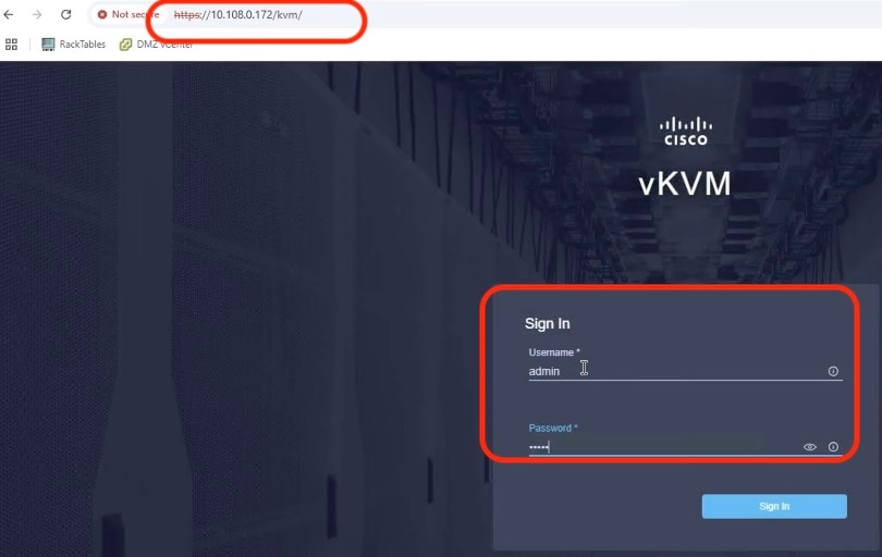
Step 3. From the KVM screen, go to Virtual Media > vKVM Mapped vDVD.
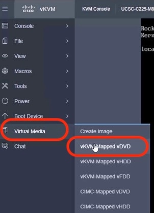
Step 4. Select the VAST operating system ISO from your local file system and click Map Drive.
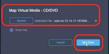
Step 5. Modify the Boot Device to Any Virtual Media, this will implement a one-time boot through virtual media and override the default Boot Order Policy. Selected one time boto media avoids manually selecting virtual media mapped ISO on node bootloader prompt.
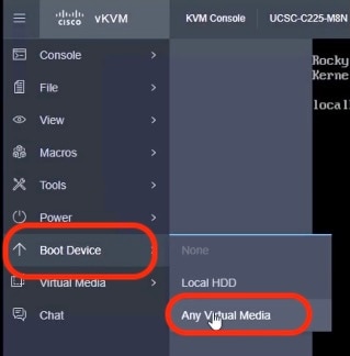
Step 6. Click Power and then click Reset System to reset the power cycle on the node. The ISO automatically loads (with virtual Media having highest priority in Boot Order Server Policy).
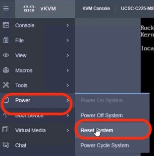
Step 7. The ISO automatically identifies the drives to install the VAST operating system ISO; the OS installation completes in about 15 to 20 minutes.
Step 8. Repeat this procedure for all the other UCS C225 M8 nodes to be configured for the VAST cluster.
This section details the VMS bootstrap process.
Note: The VMS bootstrap process detailed below is only for reference. The VAST support or install team would execute these steps either by connecting a laptop directly to the EBox tech support network port or by connecting a back-to-back network connection from EBox tech support port to a local jump server.
Note: Configure a laptop or jump server device network with 192.168.2.3/24 to connect to the bootstrap node. All EBox tech support ports are configured with IP 192.168.2.2/24
Note: If you don’t have access to a data center, you can open a KVM session to any VAST EBOX node. Assign the VAST node management IP address to the management port(enp65s0f0) of the EBox node and run vast_bootstrap.sh with the --interface option.
Procedure 1. Configure the VAST Cluster bootstrap
Step 1. SSH to 192.168.2.2 (vastdata/vastdata).
Step 2. Copy vms release to /userdata/bundles (release-5.3.0-sp8-hf6-1872389.vast.tar).
Step 3. Copy vast_bootstrap.sh script to /userdata/bundle. Change permissions to 777.
Step 4. Execute vast_bootstrap.sh.
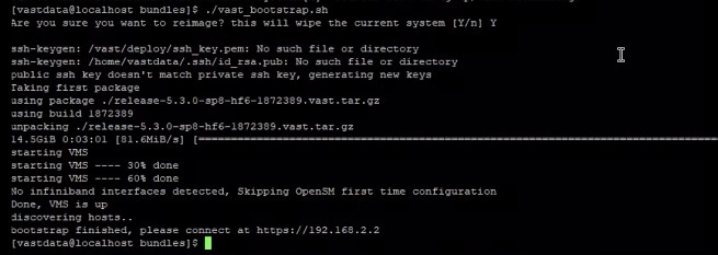
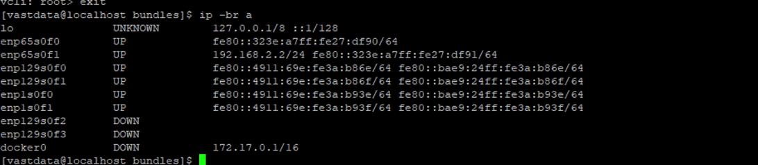
Step 5. Run the node discovery broadcast of mac address on internal switch:
enp1s0f1: flags=4163<UP,BROADCAST,RUNNING,MULTICAST> mtu 1500
inet6 fe80::4911:69e:fe3a:b93f prefixlen 64 scopeid 0x20<link>
inet6 fe80::bae9:24ff:fe3a:b93f prefixlen 64 scopeid 0x20<link>
ether b8:e9:24:3a:b9:3f txqueuelen 1000 (Ethernet)
RX packets 22156 bytes 5988804 (5.7 MiB)
RX errors 0 dropped 0 overruns 0 frame 0
TX packets 10949 bytes 2574792 (2.4 MiB)
TX errors 0 dropped 0 overruns 0 carrier 0 collisions 0
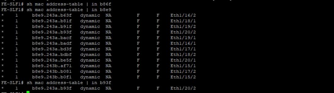
Step 6. Modify the cisco docker RPM to FALSE (non Hyperfabric deployment).
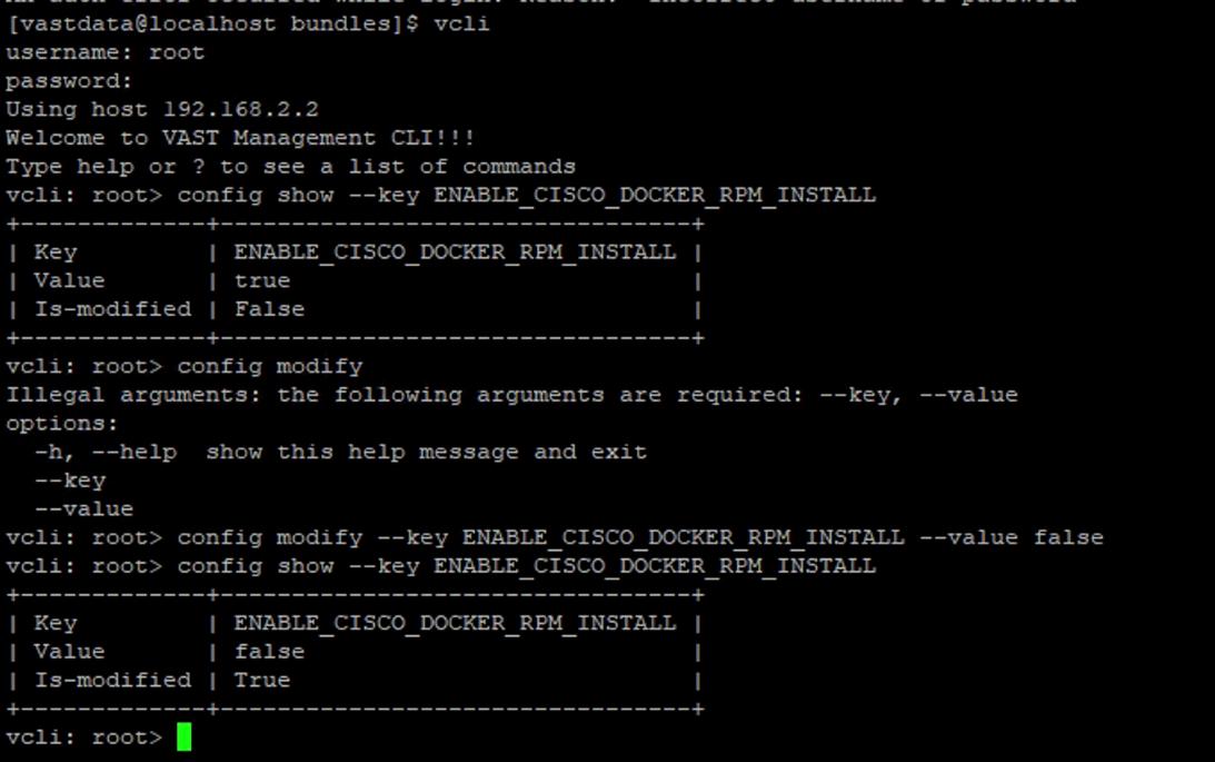
Step 7. Log into https://192.168.2.2 with username/password (admin/123456) and wait for EBox nodes to discover (Recommended an Incognito browser window).
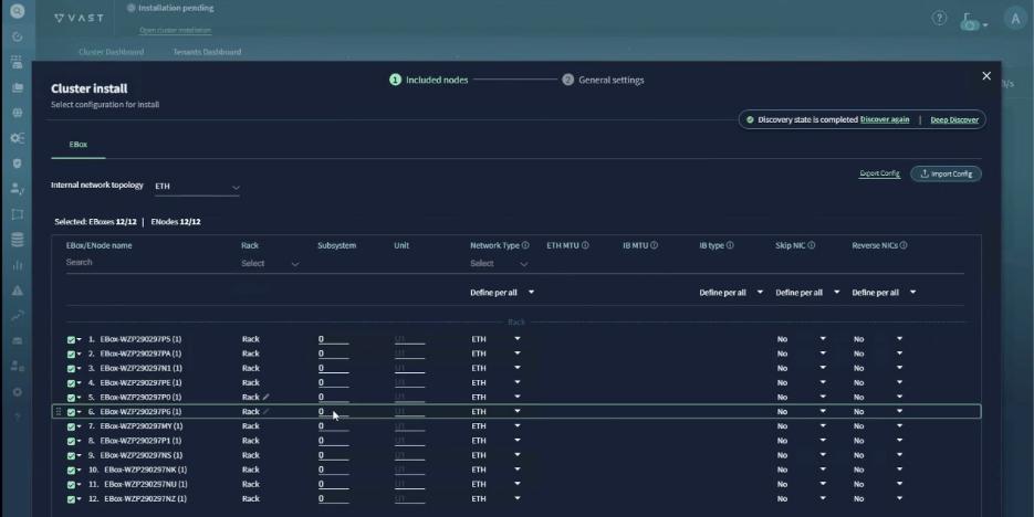
Step 8. Label the units as per the CIMC IP of nodes (ascending order). Use the serial number of nodes to identify. This can be extracted from Intersight Server dashboard:
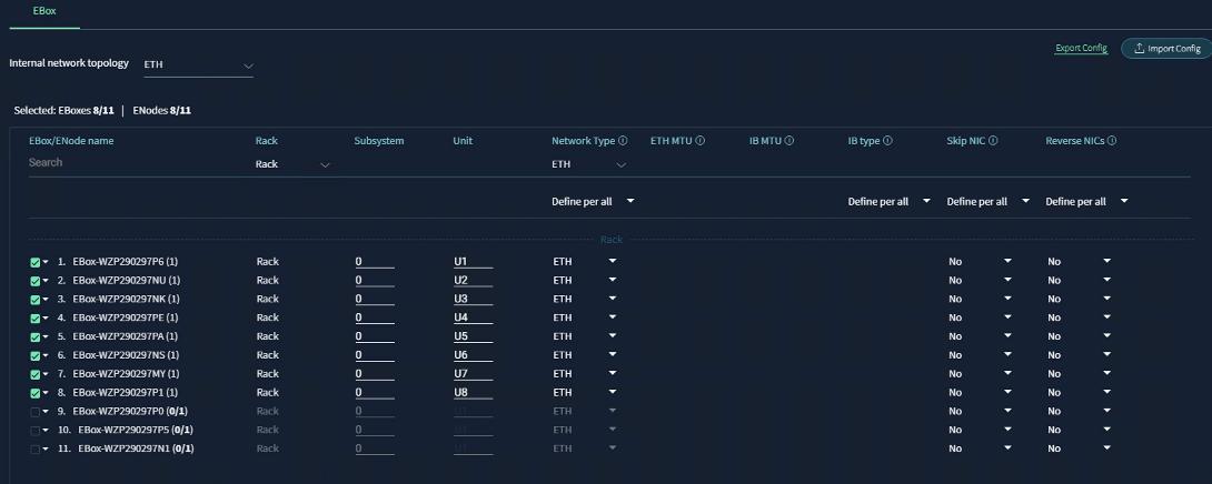
Step 9. Click Generate setting to continue to the next screen. Sort from U1 to U12.
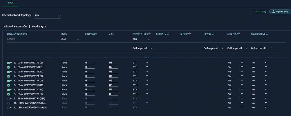
Step 10. Add the cluster configuration details as shown in the screenshot below:
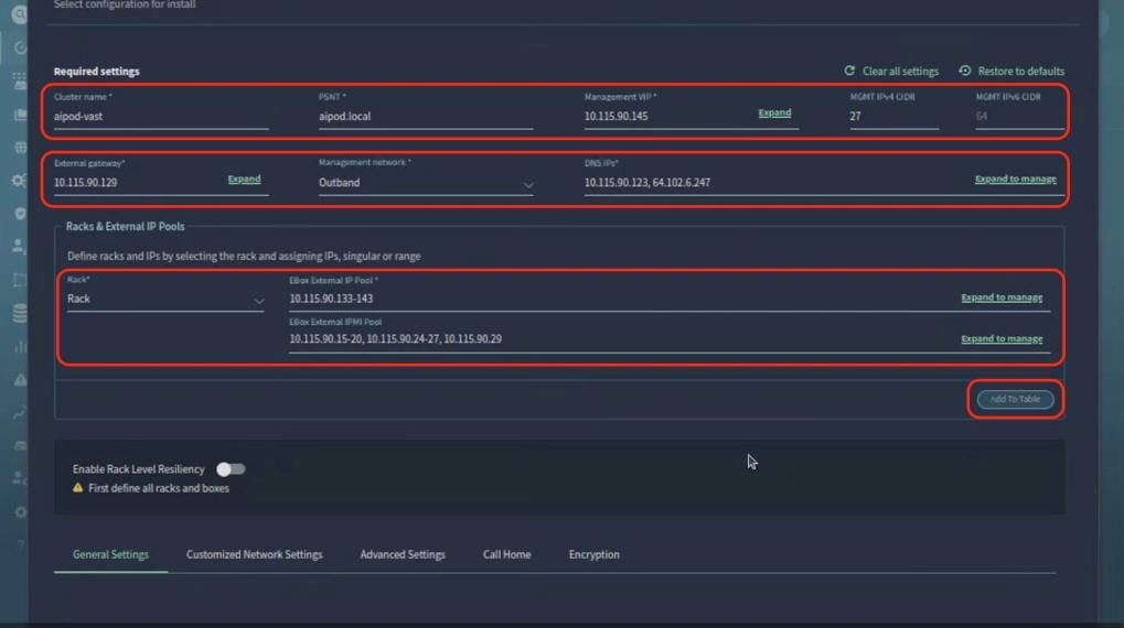
Step 11. Edit the customized network settings. Set the Data VLAN to 69 and select QoS as PFC.
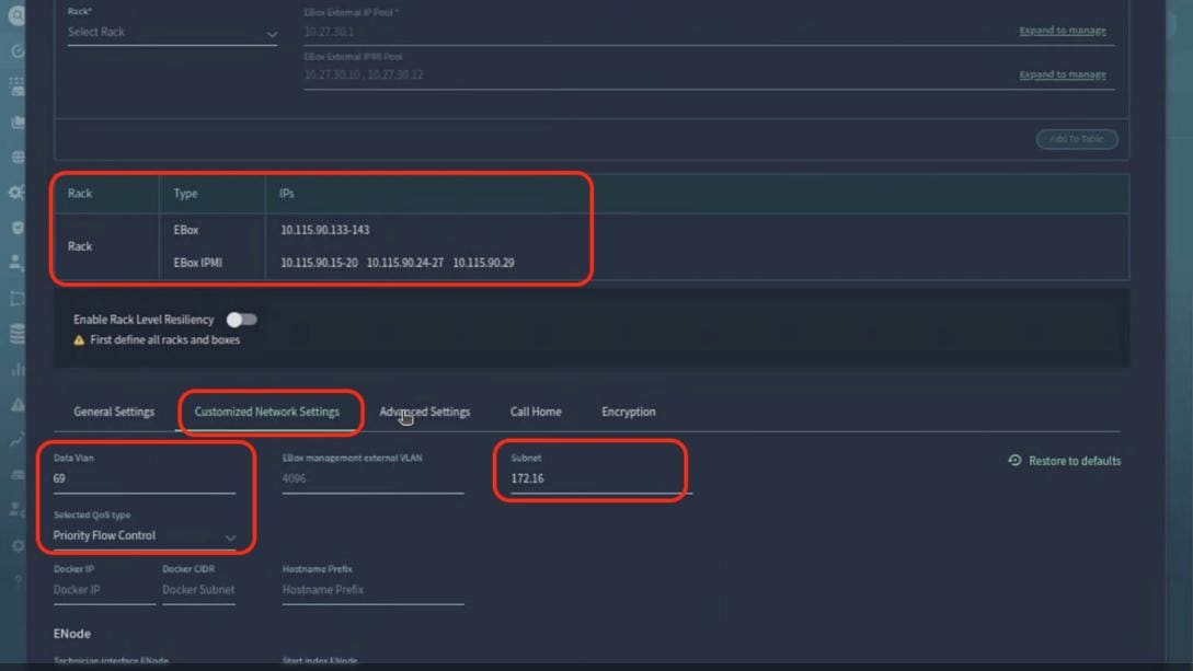
Step 12. From the Advanced Settings tab, select the SCM section layout as EBox.
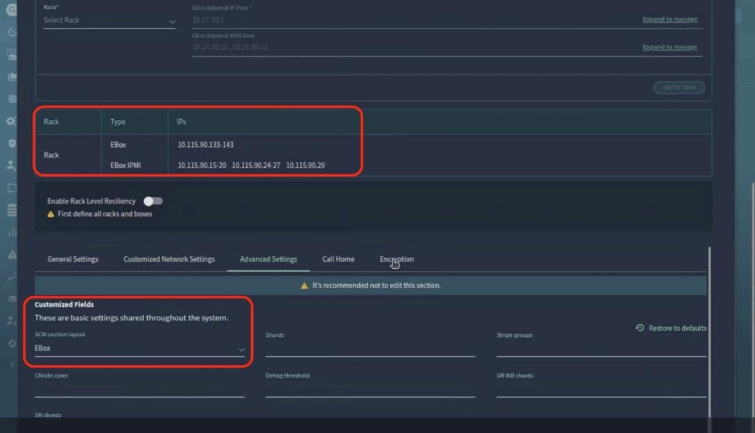
Step 13. From the General Settings tab, add NTP server, ensure B2B IPMI is disabled. Click Install Cluster.
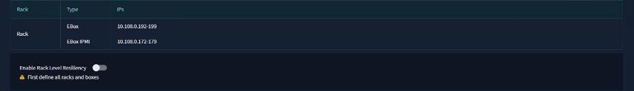
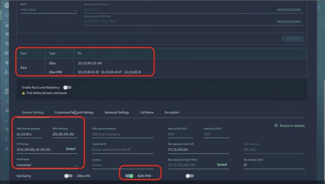

Step 14. Monitor the cluster installation progress, wait for a successful cluster deployment.
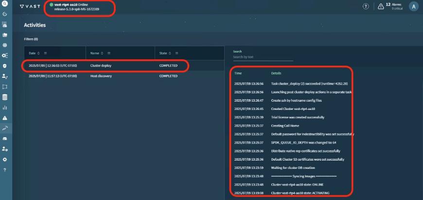
Step 15. Log into cluster VIP, (admin/123456) and confirm a successful VAST Data cluster installation.
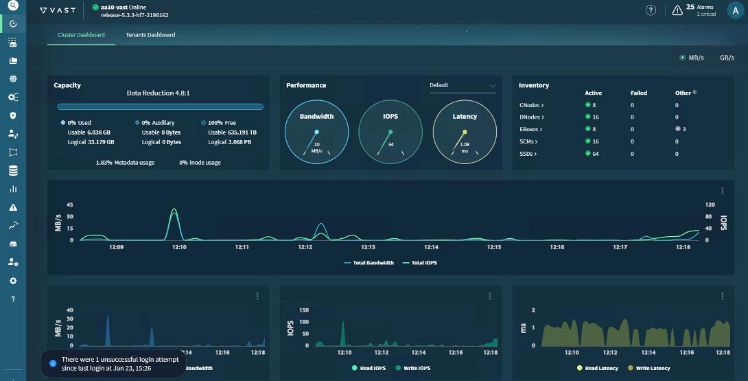
VAST Cluster Initial Setup and Validation
This section details the initial setup of VAST Cluster.
Note: See the VAST KB Article for detailed configuration for initial cluster setup.
Procedure 1. Configure Virtual IP Pool
Virtual IP pools are ranges of IP addresses that VAST Cluster can use for listening for data traffic.
VAST Data recommends a minimum of two virtual IPs per CNode. For optimal load balancing, it is encouraged to have four virtual IPs per EBox. The existing cluster had 4x 12(EBox), 48 virtual IP in the VIP pool. For detailed steps, go to Configuring Network Access. The screenshot below displays the VIP created with northbound VLAN:
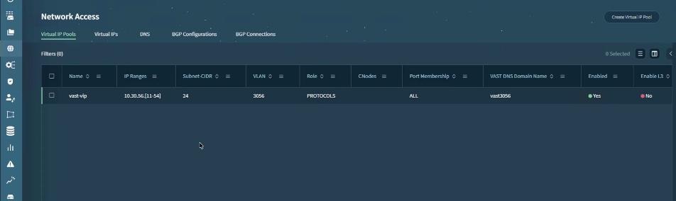
Procedure 2. Configure DNS-Based Virtual IP Balancing and DNS Forwarding
The VAST Cluster compute load is designed to be balanced across all of the CNodes. VAST Cluster features a DNS server that can handle virtual IP distribution and simplify DNS administration. The DNS server returns a single virtual IP per query and is automatically updated of virtual IP pool changes.
There are several ways to use the DNS server. It is also possible to configure virtual IP distribution on your external DNS server. There are several advantages to configuring virtual IP distribution through the VAST Cluster DNS server.
You can choose to configure the DNS-based virtual IP distribution in one of two ways:
● Using VAST Cluster DNS: In which DNS queries for subdomains are forwarded via an external DNS server to a single domain and queries are distributed to specific virtual IP pools according to subdomains.
● Using an external DNS server: In which DNS queries are forwarded by an external DNS server to all virtual IPs and the client randomly selects a virtual IP.
The existing solution leverages VAST Cluster DNS. For more details, go to VAST Cluster DNS Configuration and VAST DNS With Microsoft DNS and Delegation.
Procedure 3. Validate Cluster Install
To validate the sanity of VAST EBox cluster, customers can run vast sanity test which confirms base performance if VAST EBox cluster.
Note: You need to get the VAST sanity test kit from VAST support. This kit is an elbencho-based script to sanity check a cluster's read and write performance.
The screenshot below details the test results. The results are for sanity validation of the cluster and should not be used as an indication of actual performance of the cluster:
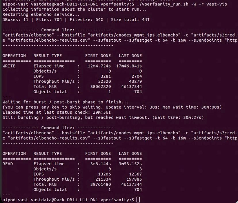
Procedure 4. Configure and Test NFSoRDMA
NFSoRDMA is supported for both NFSv3 and NFSv4,1, Remote Direct Memory Access (RDMA) is a protocol that allows for a client system to copy data from a storage server’s memory directly into that client’s own memory. NFSoRDMA is available in VAST-NFS for RHEL 7.X. and is highly recommended over the built-in version as it contains the most recent bug fixes and optimizations.
The current network fabric enables RDMA over Converged Ethernet (RoCE). The test client setup to configure and test NFSoRDMA is displayed below.
See NFSoRDMA to learn more about VAST NFS features and go to: https://vastnfs.vastdata.com/ to download VAST NFS packages.
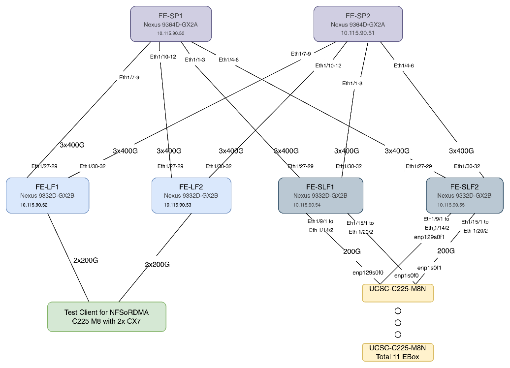
The following steps setup NFSoRDMA on the test client. (Test Client for NFSoRDMA C225 M8 with 2x CX7). The test client was installed with Ubuntu 22.04.4 LTS with kernel 6.8.0-87-generic.
Step 1. Verify the OFED driver version:
vastclient@vastclient-UCSC-C225-M8N:~$ ofed_info -s
OFED-internal-25.07-0.9.7:
Note: In event OFED driver is not installed, see How to Install MLNX_OFED Driver. You can also install NVIDIA CUDA for GPU nodes.
Step 2. Download and install VAST NFS driver. See VAST NFS for installation steps.
vastclient@vastclient-UCSC-C225-M8N:~$ vastnfs-ctl status
version: 4.5.1-vastdata-OFED-internal-25.07-0.9.7
kernel modules: sunrpc
services: rpcbind.socket rpcbind
rpc_pipefs: /run/rpc_pipefs
Step 3. Download elbencho:
wget https://github.com/breuner/elbencho/releases/download/v3.0-35/elbencho-static-x86_64.tar.gz
Step 4. Identify IP config on Test Client:
vastclient@vastclient-UCSC-C225-M8N:~$ ip -br a
lo UNKNOWN 127.0.0.1/8 ::1/128
ens4f0np0 UP 10.115.90.144/27 fe80::b65d:bed8:37bf:819/64
ens4f1np1 UP 192.168.2.3/24 fe80::657:1ea3:a8e1:abb2/64
ens3f0np0 UP 10.30.56.9/24 fe80::4a0b:5bb0:ce9:69bc/64
ens3f1np1 UP 10.30.56.8/24 fe80::b9e7:e861:4e43:11d1/64
ens1f0np0 UP 10.30.56.6/24 fe80::1393:92c3:9fab:86db/64
ens1f1np1 UP 10.30.56.7/24 fe80::cc7e:5cb7:8717:d4e1/64
Step 5. Mount the NFS view on test client. These Views are created on VAST Cluster. To identify different mount options, see VAST NFS mount parameters.
sudo mount -t nfs -o vers=3,rdma,nconnect=16,localports=10.30.56.6-10.30.56.9,remoteports=10.30.56.11-10.30.56.27,spread_reads,spread_writes 10.30.56.11:/view-c225 /mnt/c225-rdma-localport/
Step 6. Test NFSoRDMA:
./elbencho -w -b 1m -t 64 -s 20g --iodepth 16 --infloop --direct --rand /mnt/c225-rdma/file1[1-4]
./elbencho -r -b 1m -t 64 -s 20g --iodepth 16 --infloop --direct --rand /mnt/c225-rdma/file1[1-4]
Step 7. Monitor the results on VAST VMS Dashboard:
Note: The results shown below are for demonstration and should not be taken as actual cluster performance.
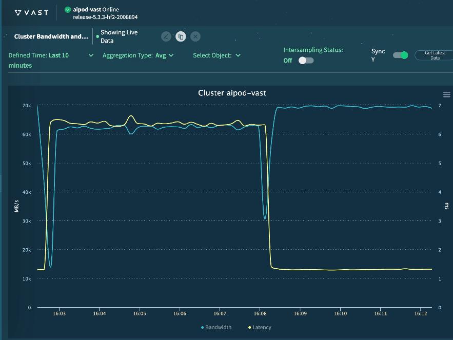
Cisco UCS C885A Configuration
This chapter contains the following:
Set up Cisco Intersight Resource Group
This section details the configuration of the Cisco UCS C885A 8-GPU servers. These servers can currently be monitored by Cisco Intersight, but policy-based configuration will come in the future. The following sections go through updating server firmware and configuring the servers for an AI training environment. This procedure will need to be followed for each C885A server. The server should be installed according to the Cisco UCS C885A M8 Server Installation and Service Guide and cabled according to the Cisco UCS C885A Connectivity Design section. Setup the Cisco BMC with either a static or DHCP IP address.
Set up Cisco Intersight Resource Group
Procedure 1. Initial C885A Setup
Step 1. From a web browser, connect to https://<BMC IP>. The default user id is root, and the default password is “password.” The first time you connect, you will be asked to set a strong password.
Step 2. When connected, click Select Timezone. From the drop-down list to select the current Timezone. Click Confirm.
Step 3. Go to Settings > Network. Ensure that all necessary network information is in place, including DNS servers and DNS Search domain.
Step 4. Go to Settings > Date and time. Enter up to three NTP servers and click Save settings. After these settings have been saved return to this screen and verify the correct time.
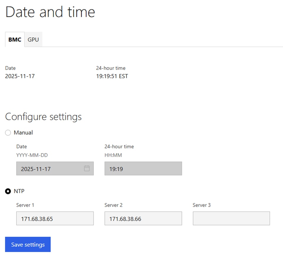
Step 5. Go to Security and access > Policies. Enable both BMC shell (via SSH) and Network IPMI (out-of-band IPMI).
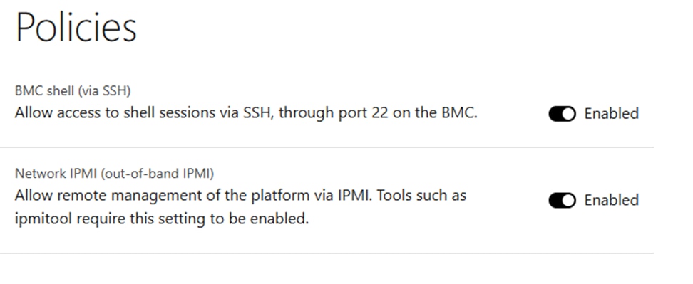
Procedure 2. Configure C885A BIOS Settings
Step 1. Configure the C885A BIOS Settings to work with AI applications.
Step 2. Go to Configure > Configure BIOS > I/O. Configure settings as shown without selecting Reboot Host Immediately. If any changes are made, click Save.
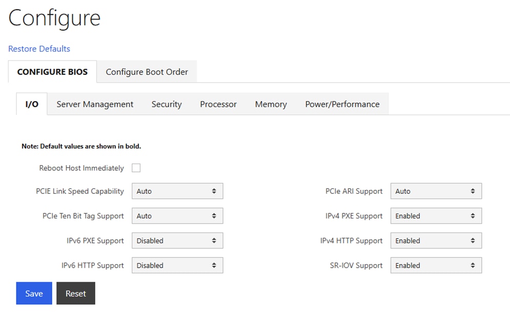
Step 3. Go to Configure > Configure BIOS > Server Management. Configure settings as shown without selecting Reboot Host Immediately. If any changes are made, click Save.
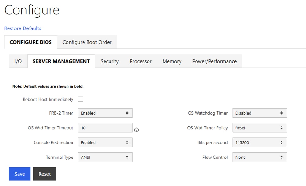
Step 4. Go to Configure > Configure BIOS > Security. Configure settings as shown without selecting Reboot Host Immediately. If any changes are made, click Save.
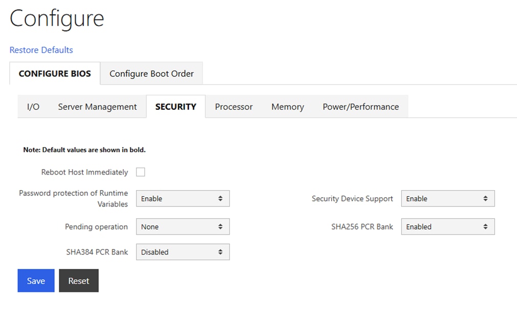
Step 5. Go to Configure > Configure BIOS > Processor. Configure settings as shown without selecting Reboot Host Immediately. If any changes are made, click Save.
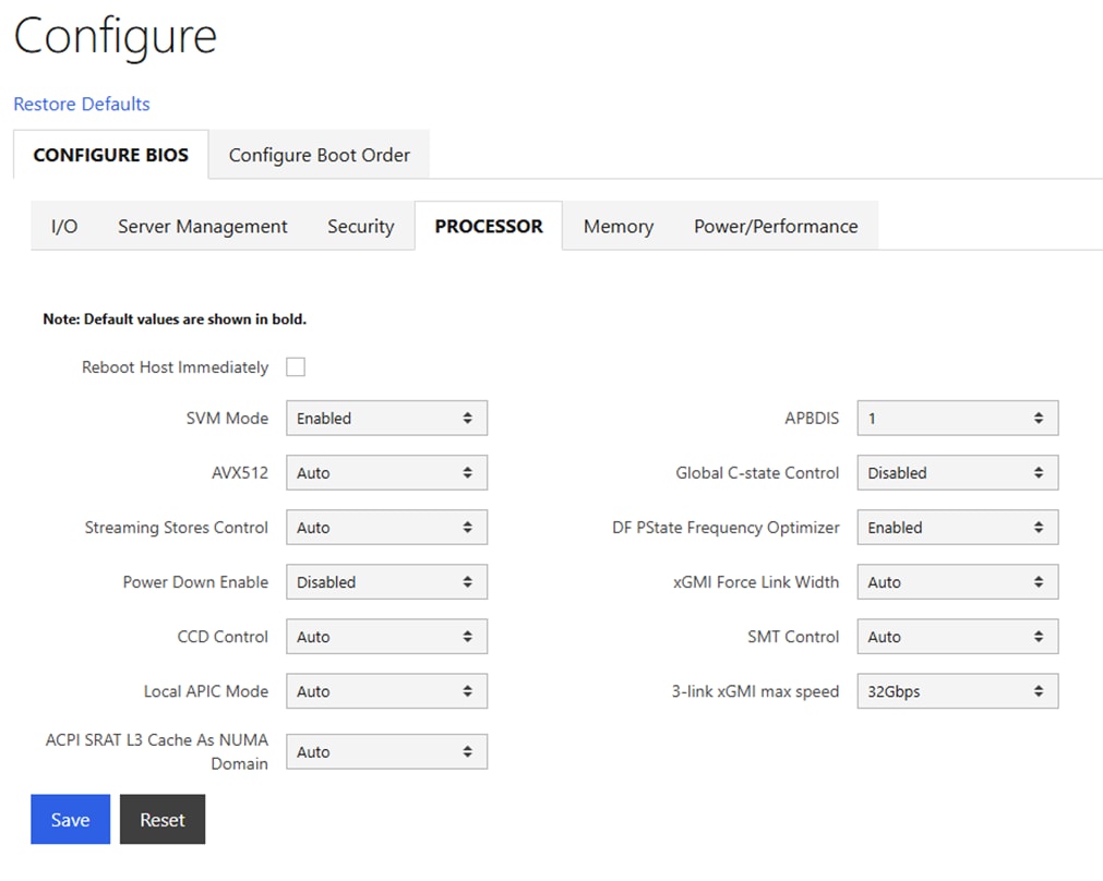
Step 6. Go to Configure > Configure BIOS > Memory. Configure settings as shown without selecting Reboot Host Immediately. If any changes are made, click Save.
Note: IOMMU should be Enabled.
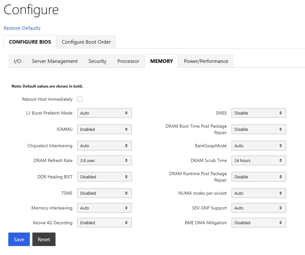
Step 7. Go to Configure > Configure BIOS > Power/Performance. Configure settings as shown and select Reboot Host Immediately. Click Save.
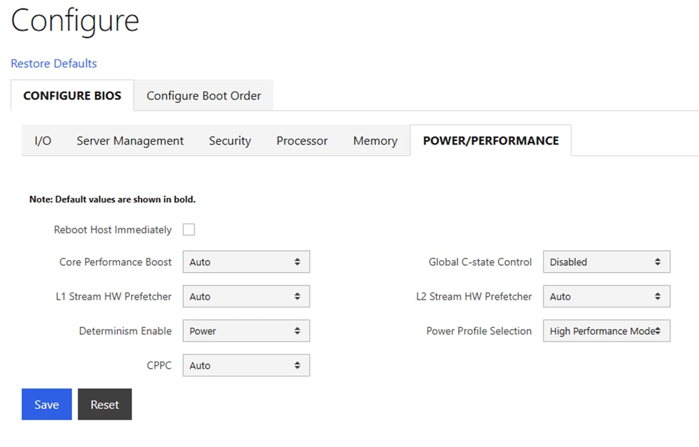
Procedure 3. Disable BlueField Internal CPU (DPU)
Note: If you have BlueField-3 (BF-3) NIC Cards in your frontend or N-S network, it is often desirable to configure the two 200G or 100G ports in an LACP bond. It has been determined that if the DPUs in the BF-3 NICs are enabled, the LACP PDUs to the switches are blocked. It is necessary to disable the DPUs for the LACP vPC port-channels on the Cisco Nexus switches to function properly. This will need to be done on all N-S BF-3 NICs on all the Cisco UCS C885As.
Step 1. In the Cisco UCS C885A BMC interface, select Hardware status > Inventory and LEDs > Network adapters. Identify the adapter(s) being used for the frontend network, expand them, and note the MAC addresses.
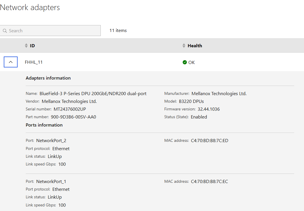
Step 2. Select Operations > KVM and click Launch KVM. The KVM will open in a separate window. On Windows, the KVM will open in full screen but can be sized down.
Step 3. From the Host Power drop-down list, select Power Cycle and click Confirm.
Step 4. When the server comes back up and you see Press <DEL> or <ESC> to enter setup, press either of those keys. You should then see an Entering Setup message.
Step 5. Use the right arrow key to move to the Advanced tab and then Arrow down until you find an Nvidia Network Adapter with a MAC address that matches what was queried in Step 1. When the adapter is highlighted, press Enter to open it. Arrow down to BlueField Internal Cpu Configuration and press Enter to open it. Arrow down to the field to the right of Internal Cpu Offload Engine and use the arrow keys and Enter key to set the field to Disabled. Hit the ESC key twice to back out to the device selection page. Repeat this process for all BF-3 ports connected to the frontend network. Press F4 to Save and Exit and click Yes to verify. The server reboots with the DPUs.
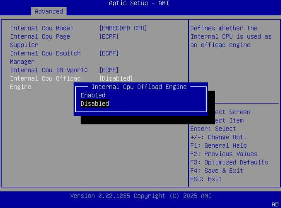
Procedure 4. Claim Cisco UCS C885A to Intersight
Cisco UCS C885A servers can be claimed into Cisco Intersight to provide detailed hardware and monitoring information. You can also access the BMC interface and the KVM interface from Intersight. To claim a C885A server into Intersight, complete the following steps.
Step 1. In the Cisco UCS C885A BMC interface, select Device connector on the left. At the same time, in Cisco Intersight in the account where you want to claim the C885A servers, select System > Targets. Click Claim a New Target and then select Cisco UCS Server (Standalone). Click Start. Select all resource groups you would like to place the server in. Copy and paste the Device ID and Claim Code from the C885A Device connector page and click Claim. After the target is claimed to Intersight, the status will update on the C885A Device connector page.
Step 2. When the server is claimed into Intersight, it will appear under Operate > Servers. Server Inventory and Metrics can be viewed and the server’s BMC and KVM interfaces can be brought up from Intersight. In order for either of these interfaces to be reached, the machine that is logged into Intersight must have routable access to the C885As’ BMC IP addresses.
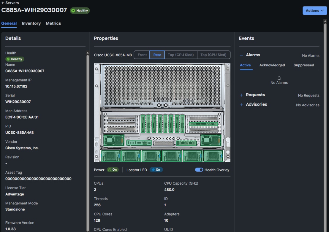
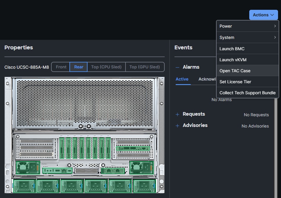
Procedure 5. Update Cisco UCS C885A Firmware
It is important to update Cisco UCS C885A firmware to at least the Suggested Release from https://software.cisco.com/download/home/286337202/type/283850974/release/1.1(0.250025). This procedure will show an update to what is currently the latest release – version 1.2(0.250011). The firmware will need to be updated individually on each server. The firmware downloads include a PCIE Switch Update Tool to update the PCIe switches between the GPUs and backend NIC cards, a server firmware upgrade script to update mainly BIOS and BMC firmware, a firmware tar.gz file containing the updated firmware, and a firmware hardware update utility ISO to update firmware in all hardware NICs in the server. At the time of publication, only the version 1.2 firmware includes the PCIE Switch Update Tool.
Step 1. Download all the desired UCS C885A M8 firmware release files from https://software.cisco.com.
Step 2. If your download included The PCIE Switch Update Tool, it can be run on Ubuntu 22.04.5 LTS or on RHEL 9.4 and run the following:
unzip pcie-switch-update-tool-04.18.00.00.zip
chmod +x pcie-switch-update-tool-04.18.00.00.run
scp pcie-switch-update-tool-04.18.00.00.run core@<c885a-hostname-or-IP>:/var/home/core/
ssh core@<c885a-hostname-or-IP>
sudo ./pcie-switch-update-tool-04.18.00.00.run
Enter option 1. If the Firmware Version is less than 04.18.00.00, then rerun the tool and select option 2.
If option 2, was entered, answer yes to the question.
Step 3. When the update is completed, drain the node and reboot the node. SSH back into the node and rerun the tool to verify the firmware update.
Step 4. The C885A BIOS and BMC update can be done from a Linux machine. For this update, power off the C885A:
sudo dnf install python3.11
pip3.11 install prettytable
tar -xzvf ucs-c885a-m8-upgrade-script-v1.5.tar.gz
python3.11 ucs-c885a-m8-upgrade-v1.5.py -B ucs-c885a-m8-1.2.0.250011.tar.gz -U <user> -P <password> -I <BMC-IP> -D
Step 5. If any of the firmware components require update, run:
python3.11 ucs-c885a-m8-upgrade-v1.5.py -B ucs-c885a-m8-1.2.0.250011.tar.gz -U <user> -P <password> -I <BMC-IP> -F
Note: The update will take at least 15 minutes to complete.
Step 6. To upgrade the remaining firmware on the server, launch the server’s KVM interface. To launch the KVM from Intersight, select Operate > Servers. Click the three dots to the right of the UCSC-885A-M8 server and select Launch vKVM. To launch the KVM from the BMC interface, select Operations > KVM and click Launch KVM. Once in the KVM window, use the Virtual Media pulldown and Map image to map the HUU ISO file to the KVM. Then use the Boot Device pulldown to select a one-time boot from CD. Finally, use the Host Power pulldown to power cycle the C885A and reboot from the HUU ISO CD. Follow the prompts to update the remaining firmware.
Procedure 6. Set Boot Order if Using NVIDIA Base Command Manager (BCM)
If you use NVIDIA BCM to run training and fine-tuning jobs on the C885A servers, the server boot order needs to be set to PXE boot from the first front-end or N-S NIC. Complete the following steps to set this boot order on all Cisco UCS C885A servers.
Note: Since the front-end NICs are mainly used in a bond, the “no lacp suspend individual command” should be present on all switch ports connected to the C885A front-end NICs.
Step 1. In the Cisco UCS C885A BMC interface, select Hardware status > Inventory and LEDs > Network adapters. Identify the adapter(s) being used for the frontend network, expand them, and note the MAC addresses.
Step 2. From the server’s BMC interface, select Configure > Configure Boot Order. Scroll down to find the first N-S NIC by MAC address with PXE. Use the up arrow on the right to move this NIC to the top of the list. Select Reboot Host Immediately and click Save.
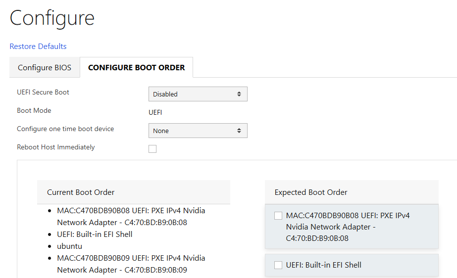
NVIDIA Base Command Manager
This chapter contains the following:
Install and Configure NVIDIA BCM
NVIDIA Base Command Manager (BCM) 10 was used in this lab validation to run ML Commons and other tests under the Simple Linux Utility for Resource Management (SLURM). BCM was used as a PXE boot target for the Cisco UCS C885A HGX Worker nodes to load an Ubuntu 22.04.4 LTS-based image with NVIDIA GPU utilities and software. NVIDIA BCM was installed on Ubuntu22.04.4 LTS in this validation on a single Cisco UCS C220 head node. BCM can also be installed on a pair of head nodes in an HA configuration. The BCM head node was connected to the front-end fabric compute leafs (where the C885As were also connected) with an LACP bonded connection that consisted of 2-100G connections from the Cisco VIC. On the bond, an IP in the management subnet was assigned and connected to a vPC in the fabric where the native VLAN for the vPC corresponded to the VLAN for the management subnet. Tagged VLAN interfaces on the bond allowed NFS and NFS over RDMA connections to storage. The NVIDIA BCM nodes were cabled according to Table 23 and mounted NFS storage from the NetApp Storage controllers.
Table 23. NVIDIA BCM Node Assignment
| Node Type |
Server Type |
Hostname |
IP |
CIMC IP |
| Head Node |
Cisco UCS C220 |
rtp5-hgx-mgt-06 |
10.115.90.115/26 |
10.115.90.7/26 |
| Worker |
Cisco UCS C885A M8 |
rtp5-hgx-hgpu-009 |
10.115.90.105 |
10.115.67.161 |
| Worker |
Cisco UCS C885A M8 |
rtp5-hgx-hgpu-010 |
10.115.90.106 |
10.115.67.162 |
| Worker |
Cisco UCS C885A M8 |
rtp5-hgx-hgpu-011 |
10.115.90.107 |
10.115.67.163 |
| Worker |
Cisco UCS C885A M8 |
rtp5-hgx-hgpu-012 |
10.115.90.108 |
10.115.67.164 |
Table 24. NVIDIA BCM Network Info
| Name |
Netmask Bits |
Base Address |
Domain Name |
| internalnet |
26 |
10.115.90.64 |
eth.cluster |
| ipminet |
26 |
10.115.67.128 |
ipmi.cluster |
| storagenet |
24 |
192.168.51.0 |
storage.cluster |
Install and Configure NVIDIA BCM
Procedure 1. Install NVIDIA BCM
NVIDIA BCM was installed on a Cisco UCS C-Series server using the NVIDIA Base Command Manager 10 Installation Manual. In the installation, Ubuntu 22.04.4 LTS was used as the underlying OS, and the SLURM Workload Manager and a type 2 network was installed.
Procedure 2. Configure BCM and Worker Nodes
Step 1. Using NVIDIA Base Command Manager 10 Administrator Manual, section 2, bring up the BCM View GUI.
Step 2. Using NVIDIA Base Command Manager 10 Administrator Manual, section 3, configure BCM.
Step 3. Using NVIDIA Base Command Manager 10 Administrator Manual, section 5, set up PXE boot and provision nodes with the base Ubuntu image.
Step 4. On one node, install all necessary drivers and tools, grab this image, and apply it to the other nodes.
Step 5. You can now run workloads such as SLURM on the nodes. For more information, see NVIDIA Base Command Manager 10 Administrator Manual, section 7. Training Applications Run under NVIDIA BCM.
Cisco UCS C885A Validation
This chapter contains the following:
This chapter details the validation of Cisco UCS C885A GPU node validation.
The MLPerf Training benchmark suite comprises full system tests that stress models, software, and hardware for a range of machine learning (ML) applications. The open-source and peer-reviewed benchmark suite provides a level playing field for competition that drives innovation, performance, and energy efficiency for the entire industry.
The MLPerf Training v5.1 benchmark suite highlighting the rapid evolution and increasing richness of the AI ecosystem as well as significant performance improvements from new generations of systems.
Llama 2 70B-LoRA: Efficient LLM Fine-Tuning
The Llama 2 70B-LoRA utilizes the massive Llama 2 70B general LLM, fine-tuning it with Parameter-Efficient Fine-Tuning (PEFT) on the SCROLLS GovReport dataset. The primary task is high-quality document summarization, with results measured against the industry-standard ROUGE algorithm. Reflecting the trend toward complex, detailed analysis, the model is configured with a long context window of 8,192 tokens.
| Feature |
Detail |
| Model |
Llama 2 70B (70 billion parameters) |
| Method |
LoRA (Low-Rank Adaptation): This Parameter-Efficient Fine-Tuning (PEFT) technique drastically reduces training time and cost by only updating a small subset of the total parameters. |
| Task |
Document Summarization on the SCROLLS GovReport dataset, designed for instruction following and general productivity tasks. |
| Accuracy |
Performance is measured until the model reaches a target quality, evaluated using the ROUGE algorithm for summary accuracy. |
| Context |
The model utilizes a long context length of 8,192 tokens, reflecting the growing need for LLMs to process and understand lengthy documents. |
Setup instructions: https://github.com/mlcommons/training_results_v5.1/tree/main/Cisco/benchmarks/llama2_70b_lora/implementations/nemo
This section details the high-level steps to setup GPU direct on Cisco UCS C885A server. If you need to setup only NFSoRDMA, see Procedure Configure and Test NFSoRDMA.
GDS was invented by NVIDIA to provide improved latency and maximal bandwidth to GPUs by bypassing the CPU. VAST-NFS also enables support for GDS.
GDS requires an RDMA-capable network and correspondingly an RDMA-enabled mount. I can be used with or without multipath.
The current network fabric enables RDMA over Converged Ethernet (RoCE). The frontend connectivity of Cisco UCS C885A is illustrated below:
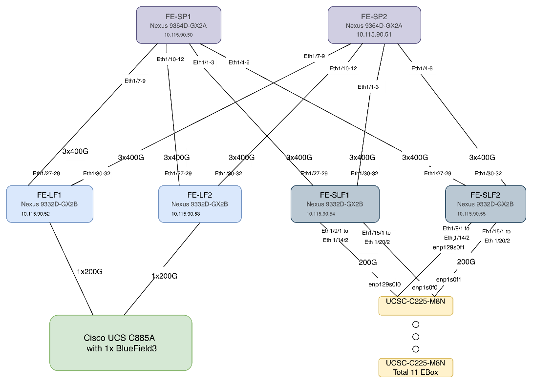
Procedure 1. Set up GPU Direct Storage
In this setup, GDS was setup on Ubuntu 22.04.4 with Linux kernel 5.15.0-1025-nvidia. Subsequent steps detail the process to update/modify the kernel version and install CUDA toolkit. The following figure displays the KVM snapshot shot of Cisco UCS C885A GPU node:
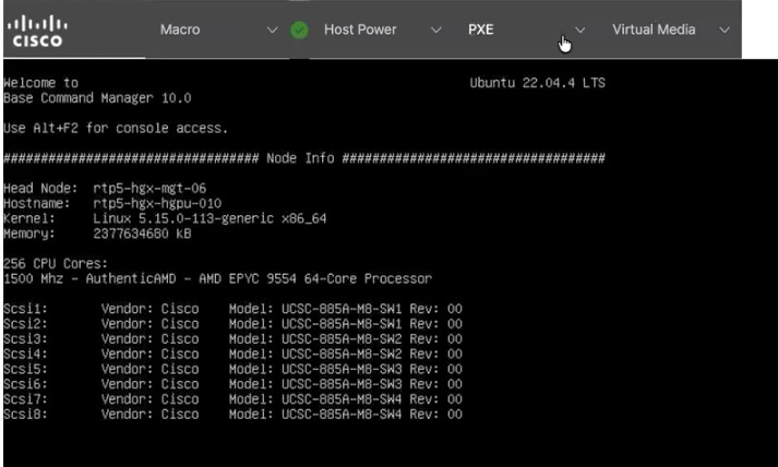
Step 1. Update the Linux kernel to 5.15.0-1025-nvidia:
#apt install linux-headers-5.15.0-1025-nvidia linux-image-5.15.0-1025-nvidia linux-modules-5.15.0-1025-nvidia linux-modules-nvidia-fs-5.15.0-1025-nvidia linux-nvidia-headers-5.15.0-1025
#apt update
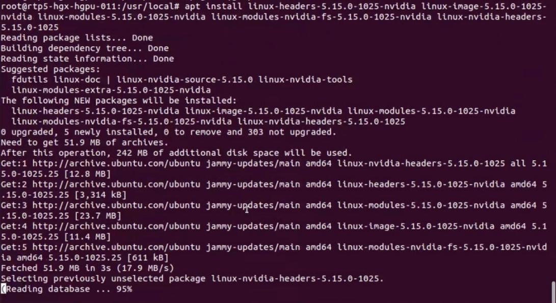
Step 2. Click OK to confirm update to Linux Kernel 5.15.0-1025-nvidia.
Step 3. Remove old kernel (5.15.0-113, update grub and reboot . After reboot, ensure the kernel is updated to 5.1.5.0-1025-nvidia.
# apt remove `dpkg -l |grep 5.15.0-113-generic|awk '{print $2}'`
#update-grub
#reboot
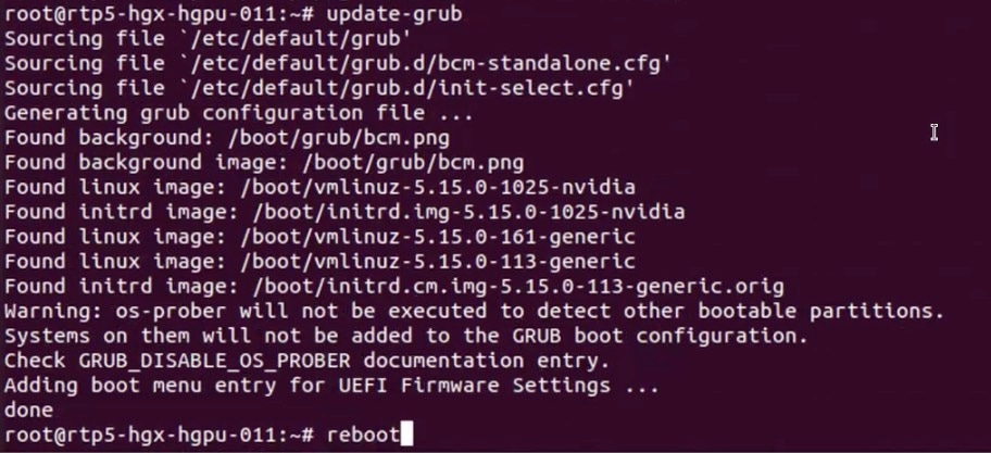

Step 4. Download CUDA toolkit 13.0.2:
# wget https://developer.download.nvidia.com/compute/cuda/13.0.2/local_installers/cuda-repo-debian12-13-0-local_13.0.2-580.95.05-1_amd64.deb
Step 5. Install the CUDA toolkit repository:
# sudo dpkg -i cuda-repo-debian12-13-0-local_13.0.2-580.95.05-1_amd64.deb

Step 6. Install the CUDA toolkit:
#sudo dpkg -i cuda-repo-debian12-13-0-local_13.0.2-580.95.05-1_amd64.deb
#sudo cp /var/cuda-repo-debian12-13-0-local/cuda-*-keyring.gpg /usr/share/keyrings/
#sudo apt-get update
#sudo apt-get -y install cuda-toolkit-13-0
Step 7. Verify successful installation of GPU Direct storage (GDS):
# python3 /usr/local/cuda/gds/tools/gdscheck.py -p

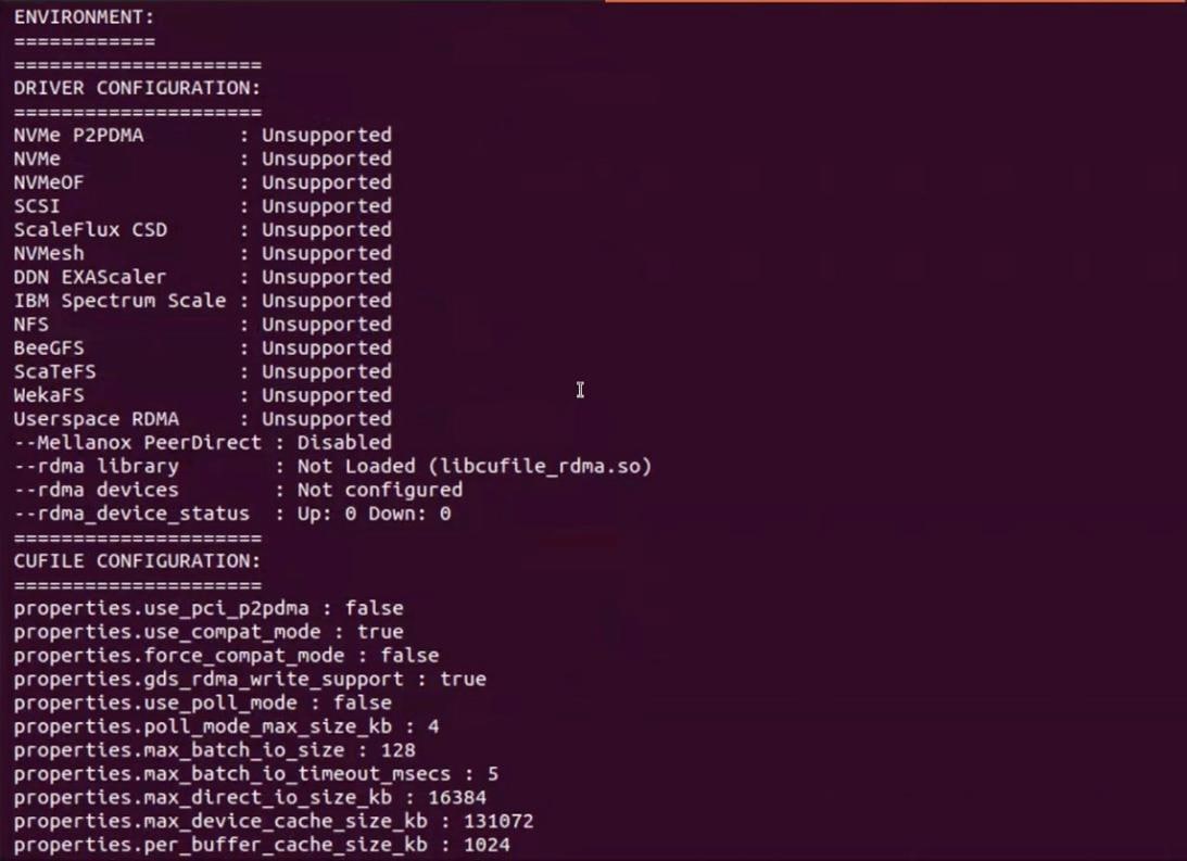
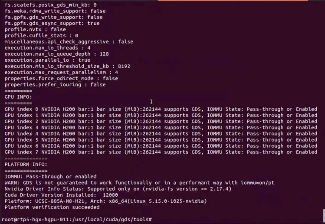
Step 8. Run nvidia-smi to verify GPUs in the node:
# nvidia-smi
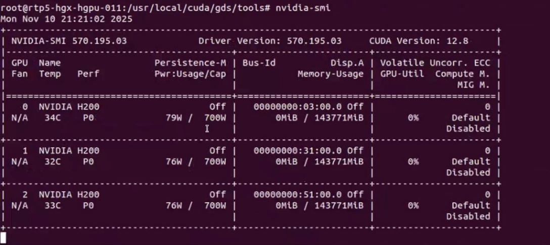
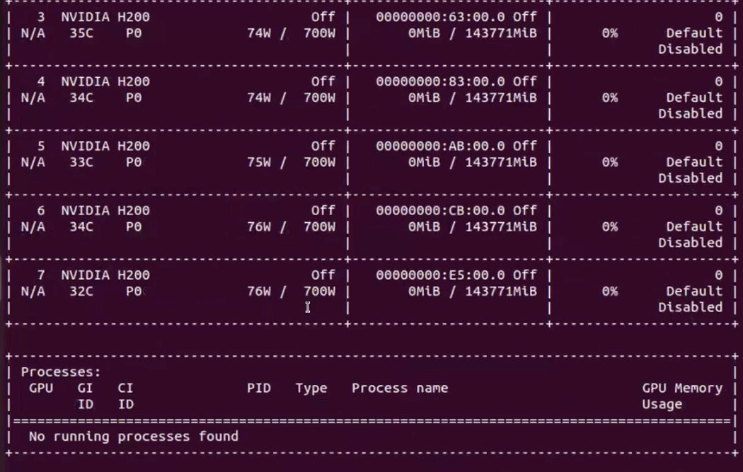
Step 9. Download the CUDA toolkit 13.0.2 and verify CUDA Toolkit headers exist, CUDA runtime library exists, GDS development headers exist and GDS runtime library exists:
# find /usr/local/cuda/ /usr/local/cuda* -name cuda_runtime.h
find /usr/local/cuda/ /usr/local/cuda* -name libcudart.so
find /usr/local/cuda/ /usr/local/cuda* -name cufile.h
find /usr/local/cuda/ /usr/local/cuda* -name libcufile.so
Step 10. Verify VAST NFS drivers are loaded:
# vastnfs-ctl status

Step 11. Mount a NFS View. The NFS view is created on VAST Storage:
# mkdir /mnt/vast-nfs
# sudo mount -t nfs -o vers=3,rdma,nconnect=16,remoteports=10.30.56.11-10.30.56.27,spread_reads,spread_writes 10.30.56.11:/view-c225 /mnt/vast-nfs/
Step 12. Verify GDS module is loaded:
# python3 /usr/local/cuda/gds/tools/gdscheck.py -p

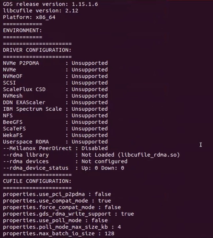
Step 13. Load the GPU Direct Storage module:
# lsmod |grep nvidia
modprobe nvidia-fs
lsmod |grep nvidia
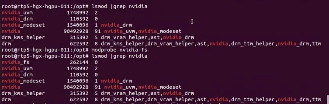
Step 14. Run gdscheck.py and verify successful load of GDS module:
# python3 /usr/local/cuda/gds/tools/gdscheck.py -p
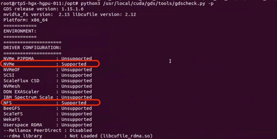
Step 15. Disable AMD_IOMMU. Add the line in /etc/default/grub.conf, run update-grub and reboot:
GRUB_CMDLINE_LINUX_DEFAULT="quiet splash iommu=pt amd_iommu=off"
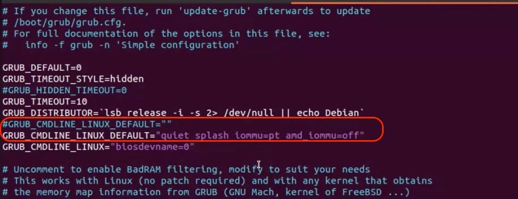
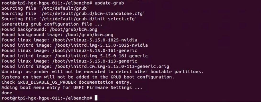
Step 16. Run gdsio to verify GPU direct storage access to VAST cluster:
# /usr/local/cuda/gds/tools/gdsio -f /mnt/vast-nfs/gdscheck -x 0 -I 0 -s 128M -i 4K -d 0

Step 17. Run long running test with gdsio (using single GPU) and verify throughput on VAST VMS Dashboard:
Note: The results shown below are for demonstration and should not be taken as actual cluster performance
# for i in {1..10};do /usr/local/cuda/gds/tools/gdsio -f /mnt/vast-nfs/gdscheck -x 0 -I 0 -s 1000000M -i 1M -d 0;done
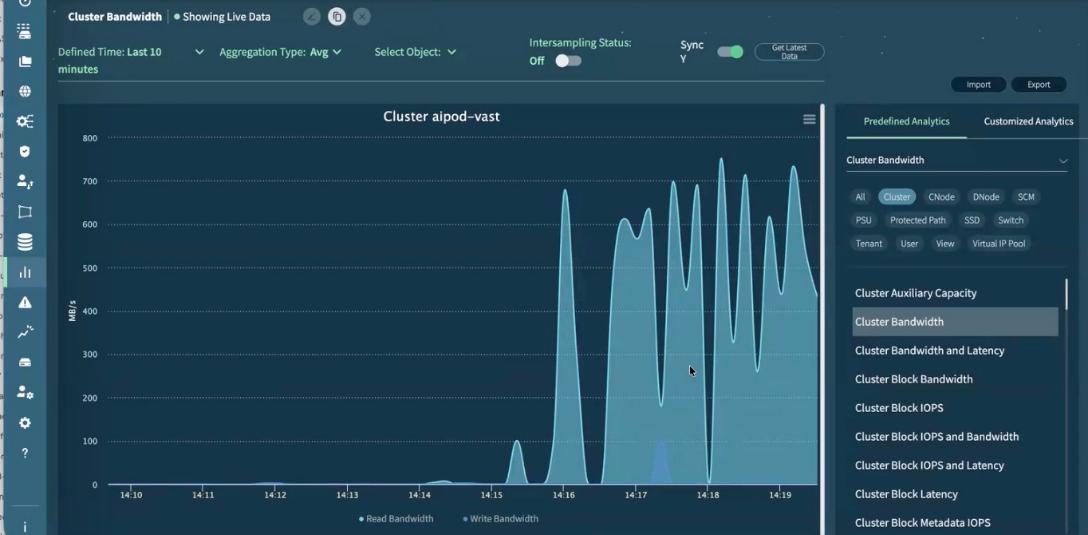
Step 18. To spread reads and writes across multiple GPU, you can create the following script and run and monitor on the VAST VMS Dashboard:
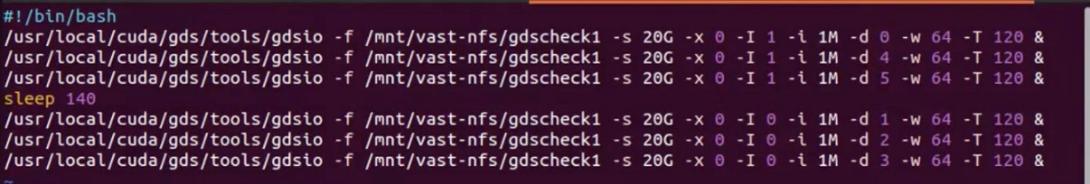
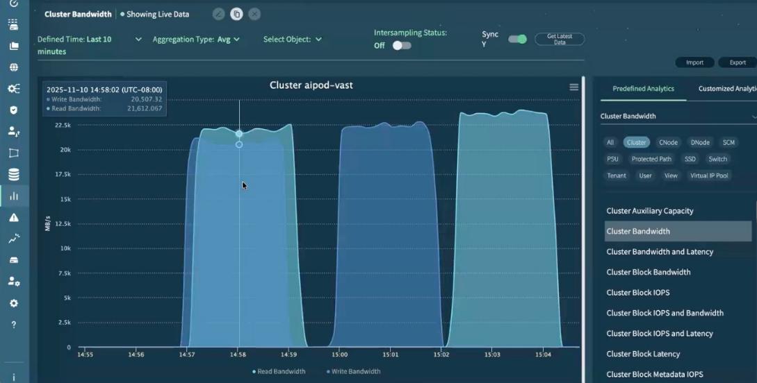
This completes the configuration and validation of GPU Direct Storage executed from Cisco UCS C885A with VAST NFS mount point.
Appendix
This appendix contains the following:
Appendix C – Bill of Materials
AI POD Solutions
Design Zone for AI Ready Infrastructure: https://www.cisco.com/c/en/us/solutions/design-zone/ai-ready-infrastructure.html
GitHub Repo for Cisco UCS Solutions: https://github.com/ucs-compute-solutions
Backend Fabric
General
Evolve your AI/ML Network with Cisco Silicon One: https://www.cisco.com/c/en/us/solutions/collateral/silicon-one/evolve-ai-ml-network-silicon-one.html
Doubling all2all Performance with NVIDIA Collective Communication Library 2.12: https://developer.nvidia.com/blog/doubling-all2all-performance-with-nvidia-collective-communication-library-2-12/
Cisco Massively Scalable Data Center Network Fabric Design and Operation White Paper: https://www.cisco.com/c/en/us/products/collateral/switches/nexus-9000-series-switches/white-paper-c11-743245.html
QoS References
Network Best Practices for Artificial Intelligence Data Center: https://www.ciscolive.com/c/dam/r/ciscolive/emea/docs/2025/pdf/BRKDCN-2921.pdf
Cisco Data Center Networking Blueprint for AI/ML Applications: https://www.cisco.com/c/en/us/td/docs/dcn/whitepapers/cisco-data-center-networking-blueprint-for-ai-ml-applications.html
RoCE Storage Implementation over NX-OS VXLAN Fabrics: https://www.cisco.com/c/en/us/td/docs/dcn/whitepapers/roce-storage-implementation-over-nxos-vxlan-fabrics.html
Load Balancing References
Nexus Improves Load Balancing and Brings UEC Closer to Adoption (Blog): https://blogs.cisco.com/datacenter/nexus-improves-load-balancing-and-brings-uec-closer-to-adoption
Cisco AI Networking for Data Center with NVIDIA Spectrum-X Solution Overview: https://www.cisco.com/c/en/us/products/collateral/networking/cloud-networking-switches/nexus-9000-switches/ai-networking-dc-nvidia-spectrum-x-so.html
Meet Cisco Intelligent Packet Flow: https://www.cisco.com/c/en/us/products/collateral/ios-nx-os-software/nx-os-software/intelligent-packet-flow-solution-overview.html
Cisco Nexus 9000 Series NX-OS Unicast Routing Configuration Guide, Release 10.5(x): https://www.cisco.com/c/en/us/td/docs/dcn/nx-os/nexus9000/105x/unicast-routing-configuration/cisco-nexus-9000-series-nx-os-unicast-routing-configuration-guide/m-configure-dynamic-load-balancing.html
AI-Ready Infrastructure: A New Era of Data Center Design: https://blogs.cisco.com/datacenter/ai-ready-infrastructure-a-new-era-of-data-center-design
Why Cisco Nexus 9000 with Nexus Dashboard for AI Networking White Paper: https://www.cisco.com/c/en/us/products/collateral/networking/cloud-networking-switches/nexus-9000-switches/nexus-9000-ai-networking-wp.html
Cisco Nexus 9000 Series Switches for AI Clusters White Paper with Performance Validation Insights: https://www.cisco.com/c/en/us/products/collateral/switches/nexus-9000-series-switches/nexus-9000-series-switches-ai-clusters-wp.html
NVIDIA
(PXN) Doubling all2all Performance with NVIDIA Collective Communication Library 2.12: https://developer.nvidia.com/blog/doubling-all2all-performance-with-nvidia-collective-communication-library-2-12/
NVIDIA Collective Communications Library (NCCL): https://developer.nvidia.com/nccl
NIVIDIA Enterprise Reference Architecture (NVIDIA does not provide links that can be shared. However, the exact titles are provided below. Cisco has access to these using NVIDIA’s Partner Portal:
● ERA-00003-001_v04 - NVIDIA HGX H100+H200+B200 8-GPU and NVIDIA Spectrum Platforms - 28th February 2025
● ERA-00010-001_v01 - Network Deployment Guide NVIDIA SpectrumX Platforms - 4th July 2025 (2)
GPUDirect: https://developer.nvidia.com/gpudirect
Splunk
Unlocking AI Performance: Splunk Observability for Cisco Secure AI Factory with NVIDIA: https://blogs.cisco.com/datacenter/unlocking-ai-performance-splunk-observability-for-cisco-secure-ai-factory-with-nvidia
Cisco UCS AI Servers
Cisco UCS Hardware Compatibility List (HCL) Tool: https://ucshcltool.cloudapps.cisco.com/public/
Cisco’s Transceiver Matrix Group:
Cisco UCS C885A M8 Server
Cisco UCS C885A M8 Data Sheet: https://www.cisco.com/c/en/us/products/collateral/servers-unified-computing/ucs-c-series-rack-servers/ucs-c885a-m8-ds.html
Cisco UCS C885A M8 Spec Sheet: https://www.cisco.com/c/dam/en/us/products/collateral/servers-unified-computing/ucs-c-series-rack-servers/ucs-c885a-m8-rack-server-spec-sheet.pdf
Cisco UCS C885A M8 Server Installation and Service Guide: https://www.cisco.com/c/en/us/support/servers-unified-computing/ucs-c-series-rack-servers/products-installation-guides-list.html
Cisco UCS C885A M8 At-a-Glance: https://www.cisco.com/c/en/us/products/collateral/servers-unified-computing/ucs-c-series-rack-servers/ucs-c885a-m8-aag.html
Cisco UCS C845A M8 Server
Cisco UCS C845A M8 Rack Server Data Sheet: https://www.cisco.com/c/en/us/products/collateral/servers-unified-computing/ucs-c-series-rack-servers/ucs-c845a-m8-rack-server-ds.html
Cisco UCS C845A M8 AI Server Spec Sheet: https://www.cisco.com/c/dam/en/us/products/collateral/servers-unified-computing/ucs-c-series-rack-servers/ucs-c845a-m8-rack-server-spec-sheet.pdf
Cisco UCS C845A M8 AI Servers Memory Guide: https://www.cisco.com/c/dam/en/us/products/collateral/servers-unified-computing/ucs-c-series-rack-servers/ucs-c845Am8-memory-guide.pdf
Cisco UCS C845A M8 Rack Server At a Glance: https://www.cisco.com/c/en/us/products/collateral/servers-unified-computing/ucs-c-series-rack-servers/ucs-c845a-m8-rack-server-aag.html
Cisco UCS C880A M8 Server
Cisco UCS C880A M8 Rack Server Data Sheet: https://www.cisco.com/c/en/us/products/collateral/servers-unified-computing/ucs-c-series-rack-servers/ucs-c880a-m8-rack-server-ds.html
Cisco UCS C880A M8 Rack Server Spec Sheet: https://www.cisco.com/c/dam/en/us/products/collateral/servers-unified-computing/ucs-c-series-rack-servers/ucs-c880a-m8-rack-server-spec-sheet.pdf
Cisco Nexus Switches
Cisco Nexus 9332D-GX2B and Nexus 9364D-GX2A Switch Data Sheet: https://www.cisco.com/site/us/en/products/collateral/networking/switches/nexus-9000-series-switches/nexus-9300-gx2-series-fixed-switches-data-sheet.html#tabs-35d568e0ff-item-4bd7dc8124-tab
Cisco Nexus 9364E-SG2 Switch Data Sheet: https://www.cisco.com/c/en/us/products/collateral/switches/nexus-9000-series-switches/nexus-9364e-sg2-switch-ds.html
Cisco Nexus Dashboard 4.1: Data Center Management for the AI Era - Cisco Blogs: https://blogs.cisco.com/datacenter/announcing-the-new-nexus-dashboard-for-simplifying-data-center-operations-in-the-ai-era
Cisco Nexus Dashboard 4.1.1 Release notes: https://www.cisco.com/c/en/us/td/docs/dcn/nd/4x/release-notes/cisco-nexus-dashboard-release-notes-411.html
Cisco Nexus Dashboard Data Sheet: https://www.cisco.com/c/en/us/products/collateral/data-center-analytics/nexus-dashboard/datasheet-c78-744371.html
Cisco Data Center Networking (DCN) Licensing Ordering Guide: https://www.cisco.com/c/en/us/products/collateral/data-center-analytics/nexus-dashboard/guide-c07-744361.html
(Internal) Cisco Nexus Dashboard 4.1 release updates - Seller Guide: https://salesconnect.seismic.com/Link/Content/DCb3d1cbc5-fb94-4583-86fe-c64261203275
(Internal) EMEA Cloud & AI Infrastructure PVT May 2025 - Exploring the Nexus Dashboard 4.x releases – PDF: https://salesconnect.seismic.com/Link/Content/DC7cce6697-d173-4ddf-892c-3d6813a17816
VAST Data
VAST Data: https://www.vastdata.com/whitepaper
Table 25. Cisco Nexus Backend Fabric Cable Connections
| Device |
Port |
Speed |
Device |
Port |
Comment |
| BE-LF1 |
mgmt0 |
1G |
management switch |
|
|
| BE-LF1 |
Eth1/1 |
400G |
C885A-1 |
CX-7 1 |
|
| BE-LF1 |
Eth1/2 |
400G |
C885A-1 |
CX-7 3 |
|
| BE-LF1 |
Eth1/3 |
400G |
C885A-1 |
CX-7 5 |
|
| BE-LF1 |
Eth1/4 |
400G |
C885A-1 |
CX-7 7 |
|
| BE-LF1 |
Eth1/5 |
400G |
C885A-2 |
CX-7 1 |
|
| BE-LF1 |
Eth1/6 |
400G |
C885A-2 |
CX-7 3 |
|
| BE-LF1 |
Eth1/7 |
400G |
C885A-2 |
CX-7 5 |
|
| BE-LF1 |
Eth1/8 |
400G |
C885A-2 |
CX-7 7 |
|
| BE-LF1 |
Eth1/9 |
400G |
C885A-3 |
CX-7 1 |
|
| BE-LF1 |
Eth1/10 |
400G |
C885A-3 |
CX-7 3 |
|
| BE-LF1 |
Eth1/11 |
400G |
C885A-3 |
CX-7 5 |
|
| BE-LF1 |
Eth1/12 |
400G |
C885A-3 |
CX-7 7 |
|
| BE-LF1 |
Eth1/13 |
400G |
C885A-4 |
CX-7 1 |
|
| BE-LF1 |
Eth1/14 |
400G |
C885A-4 |
CX-7 3 |
|
| BE-LF1 |
Eth1/15 |
400G |
C885A-4 |
CX-7 5 |
|
| BE-LF1 |
Eth1/16 |
400G |
C885A-4 |
CX-7 7 |
|
| BE-LF1 |
Eth1/17 |
400G |
BE-SP1 |
Eth1/1 |
|
| BE-LF1 |
Eth1/18 |
400G |
BE-SP1 |
Eth1/2 |
|
| BE-LF1 |
Eth1/19 |
400G |
BE-SP1 |
Eth1/3 |
|
| BE-LF1 |
Eth1/20 |
400G |
BE-SP1 |
Eth1/4 |
|
| BE-LF1 |
Eth1/21 |
400G |
BE-SP1 |
Eth1/5 |
|
| BE-LF1 |
Eth1/22 |
400G |
BE-SP1 |
Eth1/6 |
|
| BE-LF1 |
Eth1/23 |
400G |
BE-SP1 |
Eth1/7 |
|
| BE-LF1 |
Eth1/24 |
400G |
BE-SP1 |
Eth1/8 |
|
| BE-LF1 |
Eth1/25 |
400G |
BE-SP2 |
Eth1/1 |
|
| BE-LF1 |
Eth1/26 |
400G |
BE-SP2 |
Eth1/2 |
|
| BE-LF1 |
Eth1/27 |
400G |
BE-SP2 |
Eth1/3 |
|
| BE-LF1 |
Eth1/28 |
400G |
BE-SP2 |
Eth1/4 |
|
| BE-LF1 |
Eth1/29 |
400G |
BE-SP2 |
Eth1/5 |
|
| BE-LF1 |
Eth1/30 |
400G |
BE-SP2 |
Eth1/6 |
|
| BE-LF1 |
Eth1/31 |
400G |
BE-SP2 |
Eth1/7 |
|
| BE-LF1 |
Eth1/32 |
400G |
BE-SP2 |
Eth1/8 |
|
| BE-LF2 |
mgmt0 |
1G |
management switch |
|
|
| BE-LF2 |
Eth1/1 |
400G |
C885A-1 |
CX-7 2 |
|
| BE-LF2 |
Eth1/2 |
400G |
C885A-1 |
CX-7 2 |
|
| BE-LF2 |
Eth1/3 |
400G |
C885A-1 |
CX-7 6 |
|
| BE-LF2 |
Eth1/4 |
400G |
C885A-1 |
CX-7 8 |
|
| BE-LF2 |
Eth1/5 |
400G |
C885A-2 |
CX-7 2 |
|
| BE-LF2 |
Eth1/6 |
400G |
C885A-2 |
CX-7 2 |
|
| BE-LF2 |
Eth1/7 |
400G |
C885A-2 |
CX-7 6 |
|
| BE-LF2 |
Eth1/8 |
400G |
C885A-2 |
CX-7 8 |
|
| BE-LF2 |
Eth1/9 |
400G |
C885A-3 |
CX-7 2 |
|
| BE-LF2 |
Eth1/10 |
400G |
C885A-3 |
CX-7 2 |
|
| BE-LF2 |
Eth1/11 |
400G |
C885A-3 |
CX-7 6 |
|
| BE-LF2 |
Eth1/12 |
400G |
C885A-3 |
CX-7 8 |
|
| BE-LF2 |
Eth1/13 |
400G |
C885A-4 |
CX-7 2 |
|
| BE-LF2 |
Eth1/14 |
400G |
C885A-4 |
CX-7 2 |
|
| BE-LF2 |
Eth1/15 |
400G |
C885A-4 |
CX-7 6 |
|
| BE-LF2 |
Eth1/16 |
400G |
C885A-4 |
CX-7 8 |
|
| BE-LF2 |
Eth1/17 |
400G |
BE-SP1 |
Eth1/9 |
|
| BE-LF2 |
Eth1/18 |
400G |
BE-SP1 |
Eth1/10 |
|
| BE-LF2 |
Eth1/19 |
400G |
BE-SP1 |
Eth1/11 |
|
| BE-LF2 |
Eth1/20 |
400G |
BE-SP1 |
Eth1/12 |
|
| BE-LF2 |
Eth1/21 |
400G |
BE-SP1 |
Eth1/13 |
|
| BE-LF2 |
Eth1/22 |
400G |
BE-SP1 |
Eth1/14 |
|
| BE-LF2 |
Eth1/23 |
400G |
BE-SP1 |
Eth1/15 |
|
| BE-LF2 |
Eth1/24 |
400G |
BE-SP1 |
Eth1/16 |
|
| BE-LF2 |
Eth1/25 |
400G |
BE-SP2 |
Eth1/9 |
|
| BE-LF2 |
Eth1/26 |
400G |
BE-SP2 |
Eth1/10 |
|
| BE-LF2 |
Eth1/27 |
400G |
BE-SP2 |
Eth1/11 |
|
| BE-LF2 |
Eth1/28 |
400G |
BE-SP2 |
Eth1/12 |
|
| BE-LF2 |
Eth1/29 |
400G |
BE-SP2 |
Eth1/13 |
|
| BE-LF2 |
Eth1/30 |
400G |
BE-SP2 |
Eth1/14 |
|
| BE-LF2 |
Eth1/31 |
400G |
BE-SP2 |
Eth1/15 |
|
| BE-LF2 |
Eth1/32 |
400G |
BE-SP2 |
Eth1/16 |
|
| BE-SP1 |
mgmt0 |
1G |
management switch |
|
|
| BE-SP1 |
Eth1/1 |
400G |
BE-LF1 |
Eth1/17 |
|
| BE-SP1 |
Eth1/2 |
400G |
BE-LF1 |
Eth1/18 |
|
| BE-SP1 |
Eth1/3 |
400G |
BE-LF1 |
Eth1/19 |
|
| BE-SP1 |
Eth1/4 |
400G |
BE-LF1 |
Eth1/20 |
|
| BE-SP1 |
Eth1/5 |
400G |
BE-LF1 |
Eth1/21 |
|
| BE-SP1 |
Eth1/6 |
400G |
BE-LF1 |
Eth1/22 |
|
| BE-SP1 |
Eth1/7 |
400G |
BE-LF1 |
Eth1/23 |
|
| BE-SP1 |
Eth1/8 |
400G |
BE-LF1 |
Eth1/24 |
|
| BE-SP1 |
Eth1/9 |
400G |
BE-LF2 |
Eth1/17 |
|
| BE-SP1 |
Eth1/10 |
400G |
BE-LF2 |
Eth1/18 |
|
| BE-SP1 |
Eth1/11 |
400G |
BE-LF2 |
Eth1/19 |
|
| BE-SP1 |
Eth1/12 |
400G |
BE-LF2 |
Eth1/20 |
|
| BE-SP1 |
Eth1/13 |
400G |
BE-LF2 |
Eth1/21 |
|
| BE-SP1 |
Eth1/14 |
400G |
BE-LF2 |
Eth1/22 |
|
| BE-SP1 |
Eth1/15 |
400G |
BE-LF2 |
Eth1/23 |
|
| BE-SP1 |
Eth1/16 |
400G |
BE-LF2 |
Eth1/24 |
|
| BE-SP2 |
mgmt0 |
1G |
management switch |
|
|
| BE-SP2 |
Eth1/1 |
400G |
BE-LF1 |
Eth1/25 |
|
| BE-SP2 |
Eth1/2 |
400G |
BE-LF1 |
Eth1/26 |
|
| BE-SP2 |
Eth1/3 |
400G |
BE-LF1 |
Eth1/27 |
|
| BE-SP2 |
Eth1/4 |
400G |
BE-LF1 |
Eth1/28 |
|
| BE-SP2 |
Eth1/5 |
400G |
BE-LF1 |
Eth1/29 |
|
| BE-SP2 |
Eth1/6 |
400G |
BE-LF1 |
Eth1/30 |
|
| BE-SP2 |
Eth1/7 |
400G |
BE-LF1 |
Eth1/31 |
|
| BE-SP2 |
Eth1/8 |
400G |
BE-LF1 |
Eth1/32 |
|
| BE-SP2 |
Eth1/9 |
400G |
BE-LF2 |
Eth1/25 |
|
| BE-SP2 |
Eth1/10 |
400G |
BE-LF2 |
Eth1/26 |
|
| BE-SP2 |
Eth1/11 |
400G |
BE-LF2 |
Eth1/27 |
|
| BE-SP2 |
Eth1/12 |
400G |
BE-LF2 |
Eth1/28 |
|
| BE-SP2 |
Eth1/13 |
400G |
BE-LF2 |
Eth1/29 |
|
| BE-SP2 |
Eth1/14 |
400G |
BE-LF2 |
Eth1/30 |
|
| BE-SP2 |
Eth1/15 |
400G |
BE-LF2 |
Eth1/31 |
|
| BE-SP2 |
Eth1/16 |
400G |
BE-LF2 |
Eth1/32 |
|
Table 26. Cisco Nexus Frontend Fabric Cable Connections
| Device |
Port |
Speed |
Device |
Port |
Comment |
| FE-LF1 |
mgmt0 |
1G |
management switch |
|
|
| FE-LF1 |
Eth1/1 |
200G |
C885A-1 |
BF 1 |
|
| FE-LF1 |
Eth1/2 |
200G |
C885A-2 |
BF 1 |
|
| FE-LF1 |
Eth1/3 |
200G |
C885A-3 |
BF 1 |
|
| FE-LF1 |
Eth1/4 |
200G |
C885A-4 |
BF 1 |
|
| FE-LF1 |
Eth1/5 |
100G |
S9108-A |
Eth1/5 |
UCS X-Series Direct |
| FE-LF1 |
Eth1/6 |
100G |
S9108-B |
Eth1/5 |
UCS X-Series Direct |
| FE-LF1 |
Eth1/7 |
100G |
S9108-A |
Eth1/6 |
UCS X-Series Direct |
| FE-LF1 |
Eth1/8 |
100G |
S9108-B |
Eth1/6 |
UCS X-Series Direct |
| FE-LF1 |
Eth1/20/1 |
100G |
C225M6-1 |
VIC 1 |
|
| FE-LF1 |
Eth1/20/2 |
100G |
C225M6-2 |
VIC 1 |
|
| FE-LF1 |
Eth1/20/3 |
100G |
C225M6-3 |
VIC 1 |
|
| FE-LF1 |
Eth1/20/4 |
100G |
C225M6-4 |
VIC 1 |
|
| FE-LF1 |
Eth1/21 |
100G |
RTP5-BCM-MGMT |
VIC 1 |
BCM Head Node |
| FE-LF1 |
Eth1/27 |
400G |
FE-SP1 |
Eth1/7 |
|
| FE-LF1 |
Eth1/28 |
400G |
FE-SP1 |
Eth1/8 |
|
| FE-LF1 |
Eth1/29 |
400G |
FE-SP1 |
Eth1/9 |
|
| FE-LF1 |
Eth1/30 |
400G |
FE-SP2 |
Eth1/7 |
|
| FE-LF1 |
Eth1/31 |
400G |
FE-SP2 |
Eth1/8 |
|
| FE-LF1 |
Eth1/32 |
400G |
FE-SP2 |
Eth1/9 |
|
| FE-LF2 |
mgmt0 |
1G |
management switch |
|
|
| FE-LF2 |
Eth1/1 |
200G |
C885A-1 |
BF 2 |
|
| FE-LF2 |
Eth1/2 |
200G |
C885A-2 |
BF 2 |
|
| FE-LF2 |
Eth1/3 |
200G |
C885A-3 |
BF 2 |
|
| FE-LF2 |
Eth1/4 |
200G |
C885A-4 |
BF 2 |
|
| FE-LF2 |
Eth1/5 |
100G |
S9108-A |
Eth1/7 |
UCS X-Series Direct |
| FE-LF2 |
Eth1/6 |
100G |
S9108-B |
Eth1/7 |
UCS X-Series Direct |
| FE-LF2 |
Eth1/7 |
100G |
S9108-A |
Eth1/8 |
UCS X-Series Direct |
| FE-LF2 |
Eth1/8 |
100G |
S9108-B |
Eth1/8 |
UCS X-Series Direct |
| FE-LF2 |
Eth1/20/1 |
100G |
C225M6-1 |
VIC 2 |
|
| FE-LF2 |
Eth1/20/2 |
100G |
C225M6-2 |
VIC 2 |
|
| FE-LF2 |
Eth1/20/3 |
100G |
C225M6-3 |
VIC 2 |
|
| FE-LF2 |
Eth1/20/4 |
100G |
C225M6-4 |
VIC 2 |
|
| FE-LF2 |
Eth1/21 |
100G |
RTP5-BCM-MGMT |
VIC 2 |
BCM Head Node |
| FE-LF2 |
Eth1/27 |
400G |
FE-SP1 |
Eth1/10 |
|
| FE-LF2 |
Eth1/28 |
400G |
FE-SP1 |
Eth1/11 |
|
| FE-LF2 |
Eth1/29 |
400G |
FE-SP1 |
Eth1/12 |
|
| FE-LF2 |
Eth1/30 |
400G |
FE-SP2 |
Eth1/10 |
|
| FE-LF2 |
Eth1/31 |
400G |
FE-SP2 |
Eth1/11 |
|
| FE-LF2 |
Eth1/32 |
400G |
FE-SP2 |
Eth1/12 |
|
| FE-SLF1 |
mgmt0 |
1G |
management switch |
|
|
| FE-SLF1 |
Eth1/24 |
100G |
RTP5-BCM-MGMT |
PCIe3 1 |
|
| FE-SLF1 |
Eth1/27 |
400G |
FE-SP1 |
Eth1/1 |
|
| FE-SLF1 |
Eth1/28 |
400G |
FE-SP1 |
Eth1/2 |
|
| FE-SLF1 |
Eth1/29 |
400G |
FE-SP1 |
Eth1/3 |
|
| FE-SLF1 |
Eth1/30 |
400G |
FE-SP2 |
Eth1/1 |
|
| FE-SLF1 |
Eth1/31 |
400G |
FE-SP2 |
Eth1/2 |
|
| FE-SLF1 |
Eth1/32 |
400G |
FE-SP2 |
Eth1/3 |
|
| FE-SLF1 |
mgmt0 |
1G |
management switch |
|
|
| FE-SLF1 |
Eth1/24 |
100G |
RTP5-BCM-MGMT |
PCIe3 2 |
|
| FE-SLF1 |
Eth1/25 |
100G |
NetApp-01 |
e3a |
|
| FE-SLF1 |
Eth1/26 |
100G |
NetApp-02 |
e3a |
|
| FE-SLF1 |
Eth1/27 |
400G |
FE-SP1 |
Eth1/4 |
|
| FE-SLF1 |
Eth1/28 |
400G |
FE-SP1 |
Eth1/5 |
|
| FE-SLF1 |
Eth1/29 |
400G |
FE-SP1 |
Eth1/6 |
|
| FE-SLF1 |
Eth1/30 |
400G |
FE-SP2 |
Eth1/4 |
|
| FE-SLF1 |
Eth1/31 |
400G |
FE-SP2 |
Eth1/5 |
|
| FE-SLF1 |
Eth1/32 |
400G |
FE-SP2 |
Eth1/6 |
|
| FE-SP1 |
mgmt0 |
1G |
management switch |
|
|
| FE-SP1 |
Eth1/1 |
400G |
FE-SLF1 |
Eth1/27 |
|
| FE-SP1 |
Eth1/2 |
400G |
FE-SLF1 |
Eth1/28 |
|
| FE-SP1 |
Eth1/3 |
400G |
FE-SLF1 |
Eth1/29 |
|
| FE-SP1 |
Eth1/4 |
400G |
FE-SLF2 |
Eth1/27 |
|
| FE-SP1 |
Eth1/5 |
400G |
FE-SLF2 |
Eth1/28 |
|
| FE-SP1 |
Eth1/6 |
400G |
FE-SLF2 |
Eth1/29 |
|
| FE-SP1 |
Eth1/7 |
400G |
FE-LF1 |
Eth1/27 |
|
| FE-SP1 |
Eth1/8 |
400G |
FE-LF1 |
Eth1/28 |
|
| FE-SP1 |
Eth1/9 |
400G |
FE-LF1 |
Eth1/29 |
|
| FE-SP1 |
Eth1/10 |
400G |
FE-LF2 |
Eth1/27 |
|
| FE-SP1 |
Eth1/11 |
400G |
FE-LF2 |
Eth1/28 |
|
| FE-SP1 |
Eth1/12 |
400G |
FE-LF2 |
Eth1/29 |
|
| FE-SP1 |
Eth1/63.4 |
100G |
Uplink Router |
|
|
| FE-SP1 |
Eth1/64.4 |
100G |
Uplink Router |
|
|
| FE-SP2 |
mgmt0 |
1G |
management switch |
|
|
| FE-SP2 |
Eth1/1 |
400G |
FE-SLF1 |
Eth1/30 |
|
| FE-SP2 |
Eth1/2 |
400G |
FE-SLF1 |
Eth1/31 |
|
| FE-SP2 |
Eth1/3 |
400G |
FE-SLF1 |
Eth1/32 |
|
| FE-SP2 |
Eth1/4 |
400G |
FE-SLF2 |
Eth1/30 |
|
| FE-SP2 |
Eth1/5 |
400G |
FE-SLF2 |
Eth1/31 |
|
| FE-SP2 |
Eth1/6 |
400G |
FE-SLF2 |
Eth1/32 |
|
| FE-SP2 |
Eth1/7 |
400G |
FE-LF1 |
Eth1/30 |
|
| FE-SP2 |
Eth1/8 |
400G |
FE-LF1 |
Eth1/31 |
|
| FE-SP2 |
Eth1/9 |
400G |
FE-LF1 |
Eth1/32 |
|
| FE-SP2 |
Eth1/10 |
400G |
FE-LF2 |
Eth1/30 |
|
| FE-SP2 |
Eth1/11 |
400G |
FE-LF2 |
Eth1/31 |
|
| FE-SP2 |
Eth1/12 |
400G |
FE-LF2 |
Eth1/32 |
|
| FE-SP2 |
Eth1/63.4 |
100G |
Uplink Router |
|
|
| FE-SP2 |
Eth1/64.4 |
100G |
Uplink Router |
|
|
| Device |
Port |
Speed |
Device |
Port |
Comment |
| Head Node |
Management |
1G |
management switch |
|
CIMC |
| Head Node |
VIC0 |
100G |
FE-LF1 |
Eth1/21 |
|
| Head Node |
VIC1 |
100G |
FE-LF2 |
Eth1/21 |
|
| C885A-1 |
Management |
1G |
management switch |
|
CIMC |
| C885A-1 |
BF 0 |
200G |
FE-LF1 |
Eth1/1 |
N-S |
| C885A-1 |
BF 1 |
200G |
FE-LF2 |
Eth1/1 |
N-S |
| C885A-1 |
CX-7 1 |
400G |
BE-LF1 |
Eth1/1 |
E-W |
| C885A-1 |
CX-7 2 |
400G |
BE-LF2 |
Eth1/1 |
E-W |
| C885A-1 |
CX-7 3 |
400G |
BE-LF1 |
Eth1/2 |
E-W |
| C885A-1 |
CX-7 4 |
400G |
BE-LF2 |
Eth1/2 |
E-W |
| C885A-1 |
CX-7 5 |
400G |
BE-LF1 |
Eth1/3 |
E-W |
| C885A-1 |
CX-7 6 |
400G |
BE-LF2 |
Eth1/3 |
E-W |
| C885A-1 |
CX-7 7 |
400G |
BE-LF1 |
Eth1/4 |
E-W |
| C885A-1 |
CX-7 8 |
400G |
BE-LF2 |
Eth1/4 |
E-W |
| C885A-2 |
Management |
1G |
management switch |
|
CIMC |
| C885A-2 |
BF 0 |
200G |
FE-LF1 |
Eth1/2 |
N-S |
| C885A-2 |
BF 1 |
200G |
FE-LF2 |
Eth1/2 |
N-S |
| C885A-2 |
CX-7 1 |
400G |
BE-LF1 |
Eth1/5 |
E-W |
| C885A-2 |
CX-7 2 |
400G |
BE-LF2 |
Eth1/5 |
E-W |
| C885A-2 |
CX-7 3 |
400G |
BE-LF1 |
Eth1/6 |
E-W |
| C885A-2 |
CX-7 4 |
400G |
BE-LF2 |
Eth1/6 |
E-W |
| C885A-2 |
CX-7 5 |
400G |
BE-LF1 |
Eth1/7 |
E-W |
| C885A-2 |
CX-7 6 |
400G |
BE-LF2 |
Eth1/7 |
E-W |
| C885A-2 |
CX-7 7 |
400G |
BE-LF1 |
Eth1/8 |
E-W |
| C885A-2 |
CX-7 8 |
400G |
BE-LF2 |
Eth1/8 |
E-W |
| C885A-3 |
Management |
1G |
management switch |
|
CIMC |
| C885A-3 |
BF 0 |
200G |
FE-LF1 |
Eth1/3 |
N-S |
| C885A-3 |
BF 1 |
200G |
FE-LF2 |
Eth1/3 |
N-S |
| C885A-3 |
CX-7 1 |
400G |
BE-LF1 |
Eth1/9 |
E-W |
| C885A-3 |
CX-7 2 |
400G |
BE-LF2 |
Eth1/9 |
E-W |
| C885A-3 |
CX-7 3 |
400G |
BE-LF1 |
Eth1/10 |
E-W |
| C885A-3 |
CX-7 4 |
400G |
BE-LF2 |
Eth1/10 |
E-W |
| C885A-3 |
CX-7 5 |
400G |
BE-LF1 |
Eth1/11 |
E-W |
| C885A-3 |
CX-7 6 |
400G |
BE-LF2 |
Eth1/11 |
E-W |
| C885A-3 |
CX-7 7 |
400G |
BE-LF1 |
Eth1/12 |
E-W |
| C885A-3 |
CX-7 8 |
400G |
BE-LF2 |
Eth1/12 |
E-W |
| C885A-4 |
Management |
1G |
management switch |
|
CIMC |
| C885A-4 |
BF 0 |
200G |
FE-LF1 |
Eth1/4 |
N-S |
| C885A-4 |
BF 1 |
200G |
FE-LF2 |
Eth1/4 |
N-S |
| C885A-4 |
CX-7 1 |
400G |
BE-LF1 |
Eth1/13 |
E-W |
| C885A-4 |
CX-7 2 |
400G |
BE-LF2 |
Eth1/13 |
E-W |
| C885A-4 |
CX-7 3 |
400G |
BE-LF1 |
Eth1/14 |
E-W |
| C885A-4 |
CX-7 4 |
400G |
BE-LF2 |
Eth1/14 |
E-W |
| C885A-4 |
CX-7 5 |
400G |
BE-LF1 |
Eth1/15 |
E-W |
| C885A-4 |
CX-7 6 |
400G |
BE-LF2 |
Eth1/15 |
E-W |
| C885A-4 |
CX-7 7 |
400G |
BE-LF1 |
Eth1/16 |
E-W |
| C885A-4 |
CX-7 8 |
400G |
BE-LF2 |
Eth1/16 |
E-W |
| Head Node |
Management |
1G |
management switch |
|
CIMC |
| Head Node |
VIC0 |
100G |
FE-LF1 |
Eth1/21 |
|
| Head Node |
VIC1 |
100G |
FE-LF2 |
Eth1/21 |
|
Table 28. VAST EBox cluster cabling
| Device |
Port |
Speed |
Device |
Port |
Comment |
| Vast C225-1 |
PCIE3-CX7-Port2 |
200G |
FE-SLF1 |
1/9/01 |
VAST internal network |
| Vast C225-2 |
PCIE3-CX7-Port2 |
200G |
FE-SLF1 |
1/9/02 |
VAST internal network |
| Vast C225-3 |
PCIE3-CX7-Port2 |
200G |
FE-SLF1 |
1/10/01 |
VAST internal network |
| Vast C225-4 |
PCIE3-CX7-Port2 |
200G |
FE-SLF1 |
1/10/02 |
VAST internal network |
| Vast C225-5 |
PCIE3-CX7-Port2 |
200G |
FE-SLF1 |
1/11/01 |
VAST internal network |
| Vast C225-6 |
PCIE3-CX7-Port2 |
200G |
FE-SLF1 |
1/11/02 |
VAST internal network |
| Vast C225-7 |
PCIE3-CX7-Port2 |
200G |
FE-SLF1 |
1/12/01 |
VAST internal network |
| Vast C225-8 |
PCIE3-CX7-Port2 |
200G |
FE-SLF1 |
1/12/02 |
VAST internal network |
| Vast C225-9 |
PCIE3-CX7-Port2 |
200G |
FE-SLF1 |
1/13/01 |
VAST internal network |
| Vast C225-10 |
PCIE3-CX7-Port2 |
200G |
FE-SLF1 |
1/13/02 |
VAST internal network |
| Vast C225-11 |
PCIE3-CX7-Port2 |
200G |
FE-SLF1 |
1/14/01 |
VAST internal network |
| Vast C225-12 |
PCIE3-CX7-Port2 |
200G |
FE-SLF1 |
1/14/02 |
VAST internal network |
| Vast C225-1 |
PCIE1-CX7-Port2 |
200G |
FE-SLF1 |
1/15/01 |
VAST external network |
| Vast C225-2 |
PCIE1-CX7-Port2 |
200G |
FE-SLF1 |
1/15/02 |
VAST external network |
| Vast C225-3 |
PCIE1-CX7-Port2 |
200G |
FE-SLF1 |
1/16/01 |
VAST external network |
| Vast C225-4 |
PCIE1-CX7-Port2 |
200G |
FE-SLF1 |
1/16/02 |
VAST external network |
| Vast C225-5 |
PCIE1-CX7-Port2 |
200G |
FE-SLF1 |
1/17/01 |
VAST external network |
| Vast C225-6 |
PCIE1-CX7-Port2 |
200G |
FE-SLF1 |
1/17/02 |
VAST external network |
| Vast C225-7 |
PCIE1-CX7-Port2 |
200G |
FE-SLF1 |
1/18/01 |
VAST external network |
| Vast C225-8 |
PCIE1-CX7-Port2 |
200G |
FE-SLF1 |
1/18/02 |
VAST external network |
| Vast C225-9 |
PCIE1-CX7-Port2 |
200G |
FE-SLF1 |
1/19/01 |
VAST external network |
| Vast C225-10 |
PCIE1-CX7-Port2 |
200G |
FE-SLF1 |
1/19/02 |
VAST external network |
| Vast C225-11 |
PCIE1-CX7-Port2 |
200G |
FE-SLF1 |
1/20/01 |
VAST external network |
| Vast C225-12 |
PCIE1-CX7-Port2 |
200G |
FE-SLF1 |
1/20/02 |
VAST external network |
| Vast C225-1 |
PCIE3-CX7-Port1 |
200G |
FE-SLF1 |
1/9/01 |
VAST internal network |
| Vast C225-2 |
PCIE3-CX7-Port1 |
200G |
FE-SLF2 |
1/9/02 |
VAST internal network |
| Vast C225-3 |
PCIE3-CX7-Port1 |
200G |
FE-SLF2 |
1/10/01 |
VAST internal network |
| Vast C225-4 |
PCIE3-CX7-Port1 |
200G |
FE-SLF2 |
1/10/02 |
VAST internal network |
| Vast C225-5 |
PCIE3-CX7-Port1 |
200G |
FE-SLF2 |
1/11/01 |
VAST internal network |
| Vast C225-6 |
PCIE3-CX7-Port1 |
200G |
FE-SLF2 |
1/11/02 |
VAST internal network |
| Vast C225-7 |
PCIE3-CX7-Port1 |
200G |
FE-SLF2 |
1/12/01 |
VAST internal network |
| Vast C225-8 |
PCIE3-CX7-Port1 |
200G |
FE-SLF2 |
1/12/02 |
VAST internal network |
| Vast C225-9 |
PCIE3-CX7-Port1 |
200G |
FE-SLF2 |
1/13/01 |
VAST internal network |
| Vast C225-10 |
PCIE3-CX7-Port1 |
200G |
FE-SLF2 |
1/13/02 |
VAST internal network |
| Vast C225-11 |
PCIE3-CX7-Port1 |
200G |
FE-SLF2 |
1/14/01 |
VAST internal network |
| Vast C225-12 |
PCIE3-CX7-Port1 |
200G |
FE-SLF2 |
1/14/02 |
VAST internal network |
| Vast C225-1 |
PCIE1-CX7-Port1 |
200G |
FE-SLF2 |
1/15/01 |
VAST external network |
| Vast C225-2 |
PCIE1-CX7-Port1 |
200G |
FE-SLF2 |
1/15/02 |
VAST external network |
| Vast C225-3 |
PCIE1-CX7-Port1 |
200G |
FE-SLF2 |
1/16/01 |
VAST external network |
| Vast C225-4 |
PCIE1-CX7-Port1 |
200G |
FE-SLF2 |
1/16/02 |
VAST external network |
| Vast C225-5 |
PCIE1-CX7-Port1 |
200G |
FE-SLF2 |
1/17/01 |
VAST external network |
| Vast C225-6 |
PCIE1-CX7-Port1 |
200G |
FE-SLF2 |
1/17/02 |
VAST external network |
| Vast C225-7 |
PCIE1-CX7-Port1 |
200G |
FE-SLF2 |
1/18/01 |
VAST external network |
| Vast C225-8 |
PCIE1-CX7-Port1 |
200G |
FE-SLF2 |
1/18/02 |
VAST external network |
| Vast C225-9 |
PCIE1-CX7-Port1 |
200G |
FE-SLF2 |
1/19/01 |
VAST external network |
| Vast C225-10 |
PCIE1-CX7-Port1 |
200G |
FE-SLF2 |
1/19/02 |
VAST external network |
| Vast C225-11 |
PCIE1-CX7-Port1 |
200G |
FE-SLF2 |
1/20/01 |
VAST external network |
| Vast C225-12 |
PCIE1-CX7-Port1 |
200G |
FE-SLF2 |
1/20/02 |
VAST external network |
Appendix C – Bill of Materials
The Bill of Materials deployed in this solution is split into two sections:
1. Cisco UCS C885A GPU nodes with backend fabric and front end fabric including the management infrastructure. This can be found under Bill of Materials section in Cisco AI POD for Enterprise Training and Fine-Tuning Design Guide. This may change as per the end user deployment specifications.
2. VAST Storage Bill of Materials which includes 2x Cisco Nexus 9332D-GX2B switches and 11x Cisco UCS EBox nodes. This is the minimum requirements to deploy and run a VAST cluster as tested in this solution. The following table lists the Bill of Material for VAST Cluster deployed on Cisco UCS EBox nodes.
| Line Number |
Part Number |
Description |
Qty |
| 1.0 |
VAST-DATA-MLB |
VAST Software and Hardware MLB |
1 |
| 1.1 |
DC-MGT-SAAS |
Cisco Intersight SaaS |
1 |
| 1.1.1 |
SAAS-AI |
Artificial Intelligence Use Case |
1 |
| 1.1.2 |
DC-MGT-IS-SAAS-AD |
Infrastructure Services SaaS/CVA - Advantage |
11 |
| 1.1.3 |
SVS-DCM-SUPT-BAS |
Cisco Support Standard for DCM |
1 |
| 1.1.4 |
DC-MGT-UCSC-1S |
UCS Central Per Server - 1 Server License |
11 |
| 1.1.5 |
DC-MGT-ADOPT-BAS |
Intersight - Virtual adopt session http://cs.co/requestCSS |
1 |
| 1.2 |
UCSC-C225M8N-EBOX |
UCS C225 M8 1U Rack Server for VAST EBOX |
11 |
| 1.2.0.1 |
CON-L1NCO-UCSC2M8X |
CX LEVEL 1 8X7XNCDOS UCS C225 M8 1U Rack Server for VAST wit |
11 |
| 1.2.1 |
ISM-MANAGED |
Deployment mode for C Series Servers in Standalone mode |
11 |
| 1.2.2 |
UCS-CPU-A9454P |
AMD 9454P 2.75GHz 290W 48C/256MB Cache DDR5 4800MT/s |
11 |
| 1.2.3 |
UCS-MRX32G1RE3 |
32GB DDR5-5600 RDIMM 1Rx4 (16Gb) |
132 |
| 1.2.4 |
UCSC-RIS1C-225M8 |
C225 M8 1U Riser 1C PCIe Gen5 x16 FH |
11 |
| 1.2.5 |
UCSC-RIS3C-225M8 |
C225 M81U Riser 3C PCIe Gen5 x16 FH |
11 |
| 1.2.6 |
UCSC-O-ID10GC-D |
Intel X710T2LOCPV3G1L 2x10GbE RJ45 OCP3.0 NIC |
11 |
| 1.2.7 |
UCS-NVB15T3O1L |
15.3TB 2.5in U.2 15mm SolidigmP5316 HgPerf LowEnd <0.5X NVMe |
88 |
| 1.2.8 |
UCS-NVB960M1H |
960GB 2.5in U.3 15mm Micron XTR Hg Perf Ext End 60X NVMe |
22 |
| 1.2.9 |
UCSC-P-N7D200GFO |
NVIDIA OEM MCX755106AS-HEAT 2x200GbE QSFP112 PCIe Gen5 NIC |
11 |
| 1.2.10 |
UCSC-P-N7D200GFO |
NVIDIA OEM MCX755106AS-HEAT 2x200GbE QSFP112 PCIe Gen5 NIC |
11 |
| 1.2.11 |
UCS-M2-960G-D |
960GB M.2 SATA Micron G2 SSD |
22 |
| 1.2.12 |
UCS-M2-HWRAID-D |
Cisco Boot optimized M.2 Raid controller |
11 |
| 1.2.13 |
UCSC-PSU1-1200W-D |
1200w AC Titanium Power Supply for C-series Rack Servers |
22 |
| 1.2.14 |
CAB-C13-C14-2M |
Power Cord Jumper, C13-C14 Connectors, 2 Meter Length |
22 |
| 1.2.15 |
CIMC-LATEST-D |
IMC SW (Recommended) latest release for C-Series Servers. |
11 |
| 1.2.16 |
UCSC-RAIL-D |
Ball Bearing Rail Kit for C220 & C240 M7/M8 rack servers |
11 |
| 1.2.17 |
UCS-TPM2-002D-D |
TPM 2.0 FIPS 140-2 MSW2022 compliant AMD M8 servers |
11 |
| 1.2.18 |
UCSC-HSLP-C225M8 |
UCS C225 M8 Heatsink |
11 |
| 1.2.19 |
UCSC-OCP3-KIT-D |
C2XX OCP 3.0 Interposer W/Mech Assy |
11 |
| 1.3 |
N9K-C9332D-GX2B |
Nexus 9300 Series, 32p 400G Switch |
2 |
| 1.3.0.1 |
CON-L1NCD-N9KC9D3X |
CX LEVEL 1 8X7NCD Nexus 9300 Series, 32p 400G QSFP-DD |
2 |
| 1.3.1 |
MODE-NXOS |
Mode selection between ACI and NXOS |
2 |
| 1.3.2 |
NXK-AF-PI |
Dummy PID for Airflow Selection Port-side Intake |
2 |
| 1.3.3 |
NXOS-CS-10.5.4M |
Nexus 9300, 9500, 9800 NX-OS SW 10.5.4 (64bit) Cisco Silicon |
2 |
| 1.3.4 |
NXK-ACC-KIT-1RU |
Nexus 3K/9K Fixed Accessory Kit, 1RU front and rear removal |
2 |
| 1.3.5 |
NXA-SFAN-35CFM-PI |
Nexus Fan, 35CFM, port side intake airflow /w EEPROM |
12 |
| 1.3.6 |
NXA-PAC-1500W-PI |
Nexus 1500W PSU port-side Intake |
4 |
| 1.3.7 |
CAB-TA-NA |
North America AC Type A Power Cable |
4 |
| 1.3.8 |
NXOS-SLP-INFO-9K |
Info PID for Smart Licensing using Policy for N9K |
2 |
| 1.3.9 |
DCN-AI |
Select if this product will be used for AI ML Applications |
2 |
| 1.3.10 |
C1A1TN9300XF2-3Y |
Data Center Networking Advantage Term N9300 XF2, 3Y |
2 |
|
|
Initial Term - 36.00 Months | Auto Renewal Term - 0 Months | Billing Model - Prepaid Term |
|
|
| 1.3.11 |
SVS-L1N9KA-XF2-3Y |
Cisco Support Enhanced for DCN Advantage Term N9300 XF2, 3Y |
2 |
|
|
Initial Term - 36.00 Months | Auto Renewal Term - 0 Months | Billing Model - Prepaid Term |
|
|
| 1.3.12 |
DCN-ADOPT-BAS |
Nexus(DCN) - Virtual adopt session http://cs.co/requestCSS |
2 |
|
|
Initial Term - 36.00 Months | Auto Renewal Term - 0 Months | Billing Model - Prepaid Term |
|
|
| 1.3.13 |
SW-AI |
Select if this product will be used for AI ML Applications |
2 |
|
|
Initial Term - 36.00 Months | Auto Renewal Term - 0 Months | Billing Model - Prepaid Term |
|
|
| 1.4 |
QSFP-200-CU3M= |
200G QSFP56 to QSFP56 Passive Copper Cable, 3m |
44 |
| 2.0 |
QDD-400-AOC5M= |
400G QSFP-DD Active Optical Cable, 5M |
12 |
About the author
Anil Dhiman, Technical Leader, Cisco Systems, Inc.
Anil has over 20 years of experience specializing in data center solutions on Cisco UCS servers, and performance engineering of large-scale enterprise applications. Over the past 15 years, Anil has authored several Cisco Validated Designs for enterprise solutions on Cisco data center technologies. Currently, Anil's focus is on Cisco’s portfolio of hyperconverged infrastructure, data protection, SDS and Gen AI solutions using Cisco UCS.
Acknowledgements
For their support and contribution to the design, validation, and creation of this Cisco Validated Design, the author would like to thank:
● Archana Sharma, Principal Technical Marketing Engineer, Cisco Systems, Inc.
● Marina Ferreira, Principal Solutions Engineer, Cisco Systems, Inc.
● John George, Technical Marketing Engineer, Cisco Systems, Inc.
● Ramesh Isaac, Technical Marketing Engineer, Cisco Systems, Inc.
● Zaid McKie Krisberg, Tech Systems Engineering Technical Leader, Cisco Systems, Inc.
● Weiguo Sun, Principal Engineer, Cisco Systems, Inc.
● Nikhil Mitra, Site Reliability Engineering Technical Leader, Cisco Systems, Inc.
● Chris O’Brien, Senior Director, Technical Marketing, Cisco Systems, Inc.
● Oz Perry, Solutions Architect, VAST Data
● Sarathy Krishna, Customer Success, VAST Data
● John Edwards, Customer Success, VAST Data
● Bryan Schramm, Global Field CTO, VAST Data
CVD Program
ALL DESIGNS, SPECIFICATIONS, STATEMENTS, INFORMATION, AND RECOMMENDATIONS (COLLECTIVELY, "DESIGNS") IN THIS MANUAL ARE PRESENTED "AS IS," WITH ALL FAULTS. CISCO AND ITS SUPPLIERS DISCLAIM ALL WARRANTIES, INCLUDING, WITHOUT LIMITATION, THE WARRANTY OF MERCHANTABILITY, FITNESS FOR A PARTICULAR PURPOSE AND NONINFRINGEMENT OR ARISING FROM A COURSE OF DEALING, USAGE, OR TRADE PRACTICE. IN NO EVENT SHALL CISCO OR ITS SUPPLIERS BE LIABLE FOR ANY INDIRECT, SPECIAL, CONSEQUENTIAL, OR INCIDENTAL DAMAGES, INCLUDING, WITHOUT LIMITATION, LOST PROFITS OR LOSS OR DAMAGE TO DATA ARISING OUT OF THE USE OR INABILITY TO USE THE DESIGNS, EVEN IF CISCO OR ITS SUPPLIERS HAVE BEEN ADVISED OF THE POSSIBILITY OF SUCH DAMAGES.
THE DESIGNS ARE SUBJECT TO CHANGE WITHOUT NOTICE. USERS ARE SOLELY RESPONSIBLE FOR THEIR APPLICATION OF THE DESIGNS. THE DESIGNS DO NOT CONSTITUTE THE TECHNICAL OR OTHER PROFESSIONAL ADVICE OF CISCO, ITS SUPPLIERS OR PARTNERS. USERS SHOULD CONSULT THEIR OWN TECHNICAL ADVISORS BEFORE IMPLEMENTING THE DESIGNS. RESULTS MAY VARY DEPENDING ON FACTORS NOT TESTED BY CISCO.
CCDE, CCENT, Cisco Eos, Cisco Lumin, Cisco Nexus, Cisco StadiumVision, Cisco TelePresence, Cisco WebEx, the Cisco logo, DCE, and Welcome to the Human Network are trademarks; Changing the Way We Work, Live, Play, and Learn and Cisco Store are service marks; and Access Registrar, Aironet, AsyncOS, Bringing the Meeting To You, Catalyst, CCDA, CCDP, CCIE, CCIP, CCNA, CCNP, CCSP, CCVP, Cisco, the Cisco Certified Internetwork Expert logo, Cisco IOS, Cisco Press, Cisco Systems, Cisco Systems Capital, the Cisco Systems logo, Cisco Unified Computing System (Cisco UCS), Cisco UCS B-Series Blade Servers, Cisco UCS C-Series Rack Servers, Cisco UCS S-Series Storage Servers, Cisco UCS X-Series, Cisco UCS Manager, Cisco UCS Management Software, Cisco Unified Fabric, Cisco Application Centric Infrastructure, Cisco Nexus 9000 Series, Cisco Nexus 7000 Series. Cisco Prime Data Center Network Manager, Cisco NX-OS Software, Cisco MDS Series, Cisco Unity, Collaboration Without Limitation, EtherFast, EtherSwitch, Event Center, Fast Step, Follow Me Browsing, FormShare, GigaDrive, HomeLink, Internet Quotient, IOS, iPhone, iQuick Study, LightStream, Linksys, MediaTone, MeetingPlace, MeetingPlace Chime Sound, MGX, Networkers, Networking Academy, Network Registrar, PCNow, PIX, PowerPanels, ProConnect, ScriptShare, SenderBase, SMARTnet, Spectrum Expert, StackWise, The Fastest Way to Increase Your Internet Quotient, TransPath, WebEx, and the WebEx logo are registered trade-marks of Cisco Systems, Inc. and/or its affiliates in the United States and certain other countries. (LDW_P2)
All other trademarks mentioned in this document or website are the property of their respective owners. The use of the word partner does not imply a partnership relationship between Cisco and any other company. (0809R)