Provides information about the various types of cables and adapters for supporting transceivers.
This section provides information about the transceiver module network cables, cable pinouts, and console port adapter pinouts.
Cisco C9550 Series Smart Switches Hardware Installation Guide
Provides information about the various types of cables and adapters for supporting transceivers.
This section provides information about the transceiver module network cables, cable pinouts, and console port adapter pinouts.
For transceiver module installation notes, refer to
Each port must match the wavelength specifications on the other end of the cable, and the cable must not exceed the stipulated cable length. Copper 1000BASE-T SFP module transceivers use standard four twisted-pair, Category 5 cable at lengths up to 328 feet (100 meters).
A cable pinout refers to the specific arrangement of wires within a cable connector. Pinouts define how each pin is connected between the two ends of a cable.
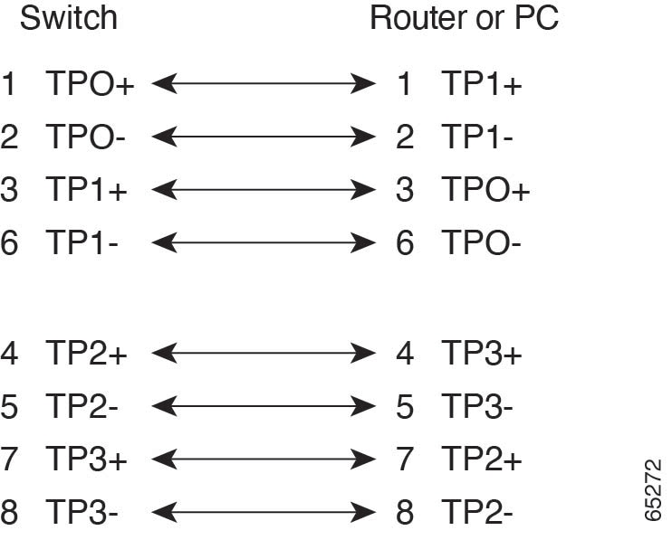
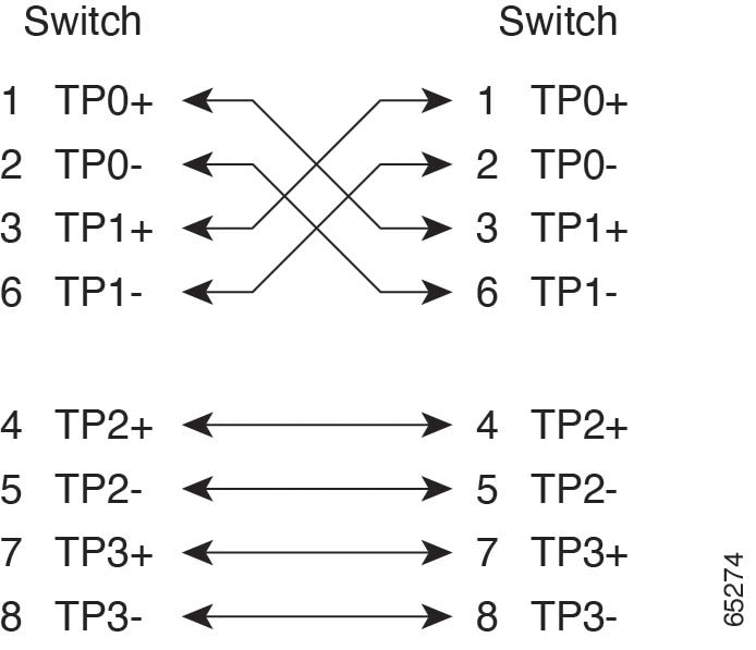
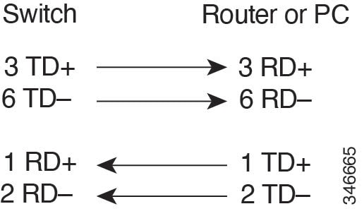
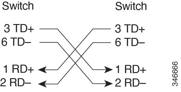
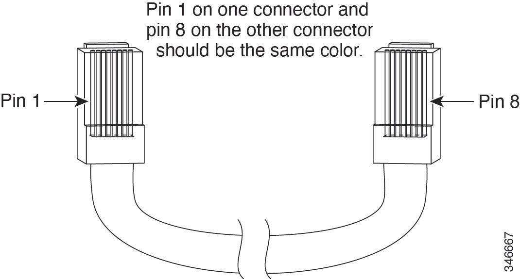
To identify a crossover cable, compare the two modular ends of the cable. Hold the cable ends side-by-side, with the tab at the back. The wire connected to the pin on the outside of the left plug should be a different color from the wire connected to the pin on the inside of the right plug.
Use an RJ-45-to-DB-9 adapter cable to connect the switch console port to a console PC. You need to provide a RJ-45-to-DB-25 female DTE adapter to connect the switch console port to a terminal.
| Switch console port (DTE) | RJ-45-to-DB-9 terminal adapter | Console device |
|---|---|---|
| Signal | DB-9 Pin | Signal |
| TxD | 2 | RxD |
| GND | 5 | GND |
| GND | 5 | GND |
| RxD | 3 | TxD |
| Switch console port (DTE) | RJ-45-to-DB-25 terminal adapter | Console device |
|---|---|---|
| Signal | DB-25 pin | Signal |
| TxD | 3 | RxD |
| GND | 7 | GND |
| GND | 7 | GND |
| RxD | 2 | TxD |
The following table summarizes the ToD/1-PPS port pinouts.
| Pin | Signal Name | Direction | Description |
|---|---|---|---|
| 1 | RESERVED | Output or input | Do Not connect |
| 2 | RESERVED | Output or input | |
| 3 | 1PPS_N | Output | 1PPS RS422 signal |
| 4 | GND | — | — |
| 5 | — | — | |
| 6 | 1PPS_P | Input | 1PPS RS422 signal |
| 7 | TOD_N | Output or input | Time-of-Day R422 output or input signal |
| 8 | TOD_P | Output or input | Time-of-Day R422 output or input signal |