Cisco C9550 Series Smart Switches Hardware Installation Guide

PDF

Cisco C9550 Series Smart Switches Hardware Installation Guide

Front-panel components

Want to summarize with AI?

Log in

Describes the front-panel components of the various SKUs of C9550 Series Smart switches.


This section describes the front-panel components of the Cisco C9550 Series Smart switches. All the switch models have similar components.

This illustration displays the front-panel of C9550-24L4CD.
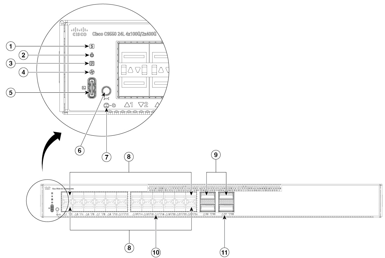
Figure 1. Front-panel of C9550-24L4CD

1

Status LED

7

Reset button

2

Blue beacon

8

24 x SFP ports

3

Power supply LED

9

4 x QSFP-DD ports

4

Fan LED

10

Downlink SFP port LEDs

5

USB-C console port

11

QSFP-DD port LEDs

6

Mode button

-

-

This illustration displays the front-panel of C9550-48L4CD.
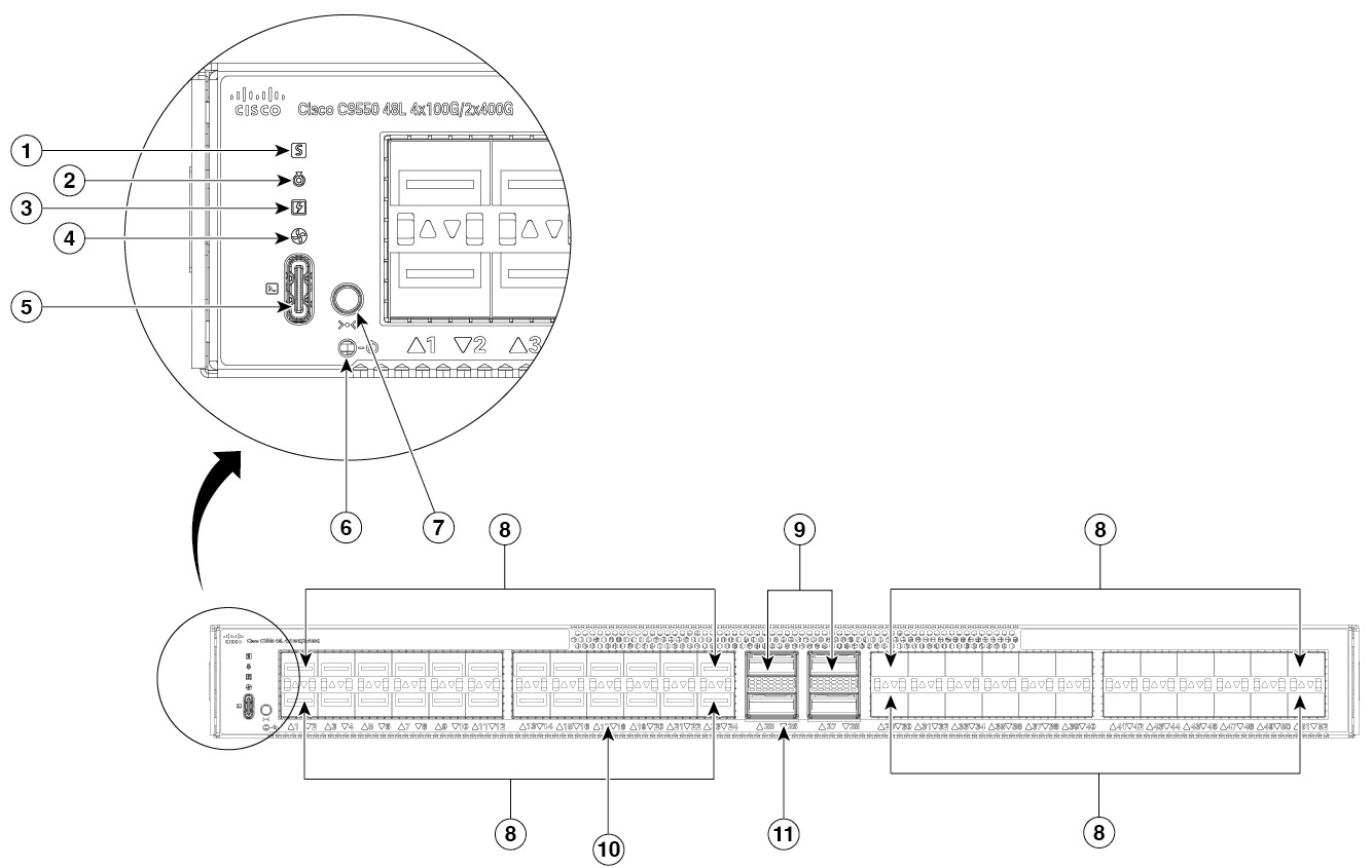
Figure 2. Front-panel of C9550-48L4CD

Front-panel of C9550-48L4CD

1

Status LED

7

Mode button

2

Blue beacon

8

48 x SFP ports

3

Power supply LED

9

4 x QSFP-DD ports

4

Fan LED

10

Downlink SFP port LEDs

5

USB-C console port

11

QSFP-DD port LEDs

6

Reset button

-

-

This illustration displays the front-panel of C9550-96L4D.
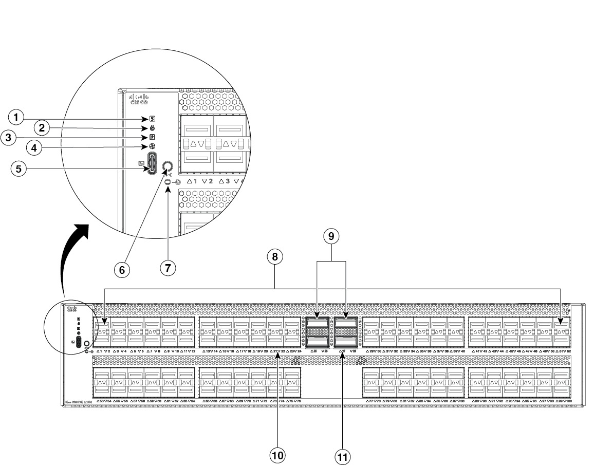
Figure 3. Front-panel of C9550-96L4D

Front-panel of C9550-96L4D

1

Status LED

7

Reset button

2

Blue beacon

8

96 x SFP​ ports

3

Power supply LED

9

4 x QSFP-DD ports

4

Fan LED

10

Downlink SFP port LEDs

5

USB-C console port

11

QSFP-DD port LEDs

6

Mode button

-

-


1PPS (I/O) DIN port

The1PPS (I/O) DIN connector is an interface that inputs or outputs a One Pulse Per Second (1PPS) timing signal for precise time synchronization, using a DIN-style 1.0/2.3 coaxial connector typically with 50-ohm impedance.


10MHz (I/O) DIN port

A 10MHz (I/O) DIN connector is an interface port used for precise frequency synchronization in networking equipment. This port can be configured as input ports from an external clocking and timing source, like GPS. It can also be configured as an output port for testing purposes.


LEDs

You can use the switch LEDs to monitor switch activity and its performance.


Beacon LEDs

The UID and the Beacon LED can be enabled by the administrator to indicate that the switch needs attention. It helps the administrator identify the switch.

There are two blue beacons—one on the front panel and one on the rear panel of the switch. The blue beacon on the front panel is an LED labeled UID, and on the back panel it is a LED labeled BEACON. The beacon can be enabled by either pressing the UID button on the switch front panel, or by using the CLI.

LED color Description

Off

The module does not need any attention.

Flashing Blue

The module requires attention. Provisioned by the administrator of the system.


Ethernet management port LEDs

This section describes the colors and the descriptions of the LEDs for link activity and link status of the Ethernet management port.

Table 1. Ethernet management port link activity LED
LED color Description

Off

Link is down.

Green

Link is up.

Table 2. Ethernet management port link status LED
LED color Description

Off

Link is down.

Green

Link is up.


Port LEDs and modes

Each SFP and QSFP module slot has a port LED. These port LEDs, as a group or individually, display information about the switch and the individual ports. The port mode determines the type of information shown by the port LEDs.

To select or change a mode, press the mode button until the desired mode is highlighted. When you change port modes, the meanings of the port LED colors also change.

Table 3. Description of switch LED colors in different modes
Port mode Port LED color Meaning
STAT (port status) Off No link, or port was administratively shut down.

Green LED

Green

Link present, no activity.

Blinking green LED

Blinking green

Activity. Port is sending or receiving data.
Alternating green-amber Link fault. Error frames can affect connectivity, and errors such as excessive collisions, CRC errors, and alignment and jabber errors are monitored for a link-fault indication.

Amber LED

Amber

Interface is blocked by Spanning Tree Protocol (STP) and is not forwarding data.

BLINKING AMBER - When there errors in the interfaces. Like collision error, FCS, RCV Err.

Blinking amber

Error in the interface. Errors can be collision, FCS (Frame Check Sequence), or RCV (Receive) errors.


System LEDs

This section describes the system LEDs on Cisco C9550 Series Smart switches.

Color System status
Off System is not powered on.

Green LED

Green

System is operating normally.


Amber LED

Amber

System is receiving power but is not functioning properly.

The failure is because of

  • fan failure,

  • system POST failure, or

  • minor environmental alarm.


Red LED

Red

System has triggered a major environmental alarm due to failed diagnostic tests or hardware failures.

Management port

The switch supports an Ethernet management port, also referred to as the Gi0/0 or GigabitEthernet0/0 port, This port is a Virtual Routing and Forwarding (VRF) interface to which you connect a PC. It supports TFTP for image downloading, SFTP for secure image downloading, network management, SNMP, Telnet, and SSH connections.

The switches support out-of-band (OOB) management through the Mgmt-vrf. The Mgmt-vrf is used to segment management traffic from the global routing table of the switch. The Ethernet management port supports speeds up to 10/100/1000 Mbps and is set to auto-negotiate.

When managing a switch, connect the PC to the management port of the switch.


Optional RFID

This chassis has an optional built-in, front-facing, passive Radio Frequency Identification (RFID) tag that uses Ultra High Frequency (UHF) RFID technology and requires an RFID reader with compatible software. It provides auto-identification capabilities for asset management and tracking. The RFID tags are compatible with the Generation 2 GS1 EPC Global Standard and are ISO 18000-6C compliant. They operate in the 860- to 960-MHz UHF band. For more information, see Radio Frequency Identification (RFID) on Cisco Catalyst 9000 Family Switches White Paper.

For Cisco C9550 Series Smart Switches, the RFID tag is optional. Based on your requirements, you can choose to order the switch with or without an RFID tag at the time of purchase through the PID.


Reset button

A recessed access button is available on the front panel of the C9550 Series Smart switches to reset and restart the module. Using a pin, press and hold the button inwards for 5 seconds to reset and restart the module.


SFP and QSFP module ports

Small Form-Factor Pluggable (SFP) ports are slots that accommodate SFP transceiver modules. These ports connect network equipment using either fiber optic or copper cabling, depending on the type of SFP module.

Quad Small Form-Factor Pluggable (QSFP) ports are high-speed, high-density network interfaces that accommodate QSFP transceiver modules. These ports are primarily used for data center, enterprise, and service provider environments where large amounts of data need to be transmitted quickly and efficiently. QSFP+ ports support data rates upto 40G.

QSFP-double density (DD) ports offer double the high-speed electrical interfaces as QSFP28 while maintaining the same port density. When combined with higher transmission rates per electrical interface (28G to 56G to 112G), QSFP-DD optical transceivers can increase 100G data rates to 400G.


TOD PTP RJ-45 port

A standard Cisco Time-of-Day (ToD) RJ-45 port—used for GPS and network synchronization—typically utilizes an RS-422 signal interface to send or receive clock and 1PPS (Pulse Per Second) signals.

TOD refers to a time source or time-stamping capability available at the hardware or system level for precise timekeeping. It may be used in conjunction with the Precision Time Protocol (PTP) to obtain and distribute the exact time-of-day information across devices.


USB Type C ports

  • The USB-C console port

    • Serves as a serial console interface for device management.

    • Connects a computer or terminal directly to the Cisco device for configuration purposes.

    • Enables terminal communication to configure routers, switches, firewalls, or other Cisco network devices.

The USB console takes precedence over the RJ-45 console. When a cable is connected to the USB console port, the RJ-45 console port becomes inactive, and when the USB cable is disconnected from the USB console port, the RJ-45 port becomes active.

You can configure an inactivity timeout, which reactivates the RJ-45 console if the USB console has been activated and no activity has occurred on the console for a specified amount of time.

After the USB console deactivates due to inactivity, you must disconnect and reconnect the USB cable to reactivate the USB console.