Describes how to rack mount the switch on different type of racks.
This section describes the different types of rack mount brackets, how attach the rack mount brackets, and mount the switch.
Before your rack mount your switch, follow these guidelines.
Determine which end of the chassis is to be located in the cold aisle as follows:
If the switch has port-side intake modules (fan modules with burgundy coloring), position the switch so that its ports will be in the cold aisle.
If the switch has port-side exhaust modules (fan modules with blue coloring), position the switch so that its fan and power supply modules will be in the cold aisle.
Determine which way the chassis should slide in and out of the rack—port-side entry first or rear-side entry first. You might consider whether the front or back of the rack provides better clearance for maneuvering the chassis in and out during installation and servicing. The end that needs to enter the rack first requires the guides and the other end the brackets.
Attach rack mount brackets
You can rack mount the Cisco C9550 Series Smart switches, into the front, middle, or rear of the switch. Use M4.0x6mm Phillips flat-head screws to attach the long side of the bracket to each side of the switch.
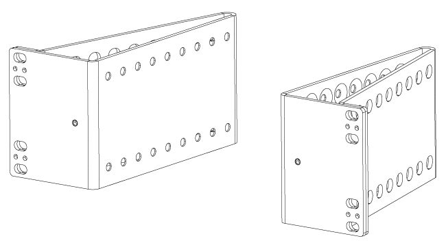
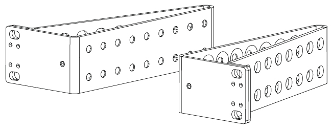
This section displays the two-post rack-mount brackets used on the 1RU and 2RU C9550 Series Smart switches.
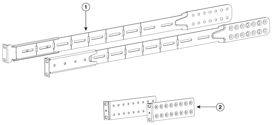
Figure 1. Two-post rack-mount brackets for 1RU switches
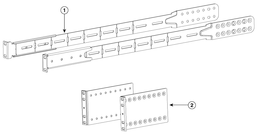
Figure 2. Two-post rack-mount brackets for 2RU switches
Rack mount the switch on two-post racks
Rack mount the switch into a 2-post rack
Procedure
1.
Install two rack–mount brackets onto the switch.
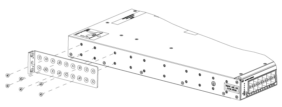
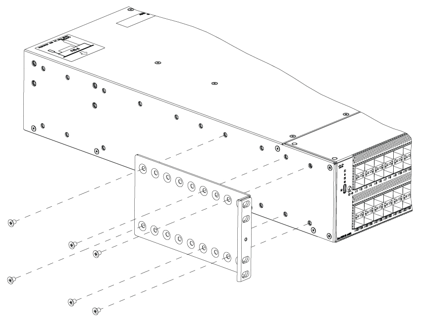
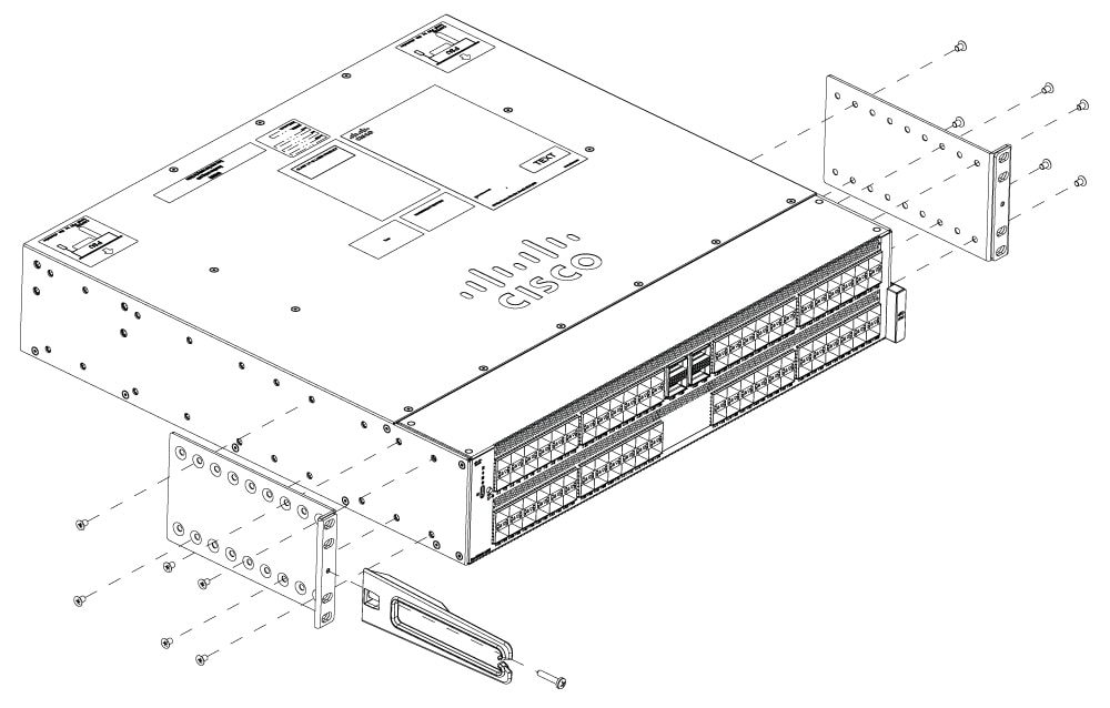
Position a rack-mount bracket so that four of its screw holes are aligned to the screw holes on the side of the chassis.
Figure 3. Attaching the two-post rack-mount brackets on a 1RU switch
Figure 4. Attaching the two-post rack-mount brackets on a 2RU switch
You can align any four of the holes in the rack-mount bracket to four of the six screw holes on the side of the chassis. The holes that you use depend on the requirements of your rack and the amount of clearance.
You can install the rack-mount bracket either at the front or rear of the chassis. The choice is determined by which end of the chassis will be inserted into the rack first. If the rear end of the chassis is to be inserted first, then mount the brackets on the front of the chassis, and vice versa.
If you are installing the chassis into an ungrounded rack, you must attach a customer-supplied grounding wire to the chassis. However, if you are installing the chassis into a grounded rack, you can skip this step.
2.
Install the switch onto the 2-post rack.
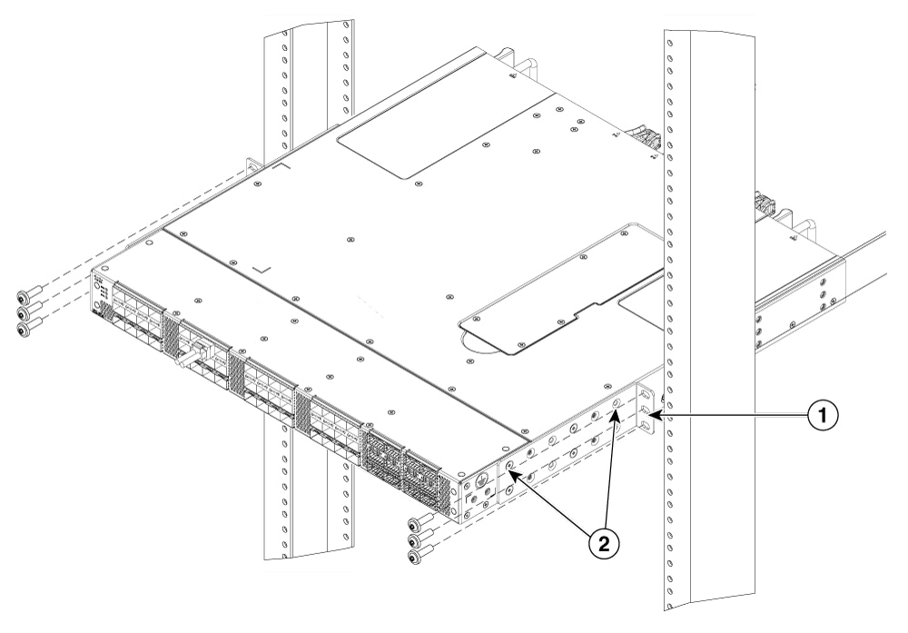
Holding the switch with both hands, position the back of the switch between the two posts of the rack. Then gently move the switch until the rack-mount brackets come in contact with two rack posts.
Holding the chassis level, insert three screws (12-24 or 10-32, depending on the rack type) into each of the two rack-mount brackets (using a total of six screws) and into the cage nuts or threaded holes in the rack or cabinet posts.
Figure 5. Installing the switch onto the 2-post rack from the front side of the chassis
1
Two-post rack
2
Mounting brackets
Tighten the 10-32 screws to 20 in-lb (2.26 N.m) or tighten the 12-24 screws to 30 in-lb (3.39 N.m).
3.
If you have attached a grounding wire to the chassis grounding pad, connect the other end of the wire to the facility ground.
Rack mount the switch on four-post racks
To install the switch on four-post racks, you must attach the rack mounting guides to the switch, install the slider rails, slide the switch into the slider rails, and secure the switch to the front of the rack. Typically, the front of the rack is the side that is easiest to access for maintenance.
Before you begin
Ensure that the rack is installed and secured to its location.
Determine how you want to set up your switch.
Procedure
1.
Use the Phillips machine screws to attach the brackets and the extension rail to the switch.
Position the mount brackets and extension rails such that the screw holes are aligned to the screw holes on the switch, and secure the brackets and extension rails to both sides the switch.
Figure 6. Four-post rack-mount kit for 1RU switches
Figure 7. Four-post rack-mount kit for 2RU switches
2.
Install the extension rails into the rack or cabinet.
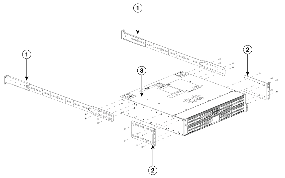
Figure 8. Attaching extension or slider rails
1
Extension rails
3
Cisco C9550 Series Smart switch
2
Mounting brackets
-
Determine which two posts of the rack or cabinet you should use for the extension rails. Of the four vertical posts in the rack or cabinet, two will be used for the rack-mount brackets, and the other two posts will have the extension rails.
Position a extension rail at the desired level side of the rack and use two 12-24 screws or two 10-32 screws, depending on the rack thread type, to attach the extension rail to the rack.
Attach the other extension rail to the other side of the rack. To make sure that the extension rails are at the same level, you should use a level tool or tape measure, or carefully count the screw holes in the vertical mounting posts.
3.
Secure the switch to the rack rails using the number-12 or number-10 Phillips machine screws provided with the accessory kit.
Hold the switch with both hands, position the rack-mount brackets on the switch between the rack or cabinet posts that do not have extension rails attached to them.
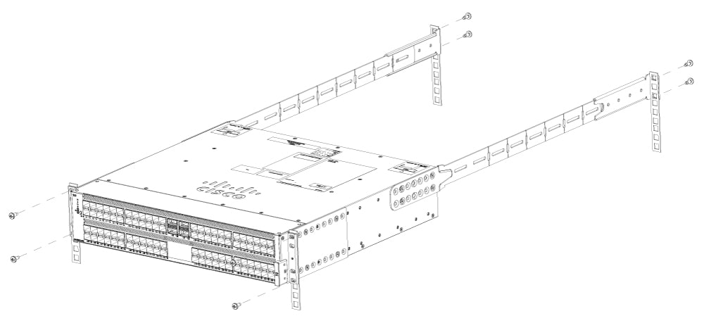
Figure 9. Mounting the switch in a rack
Align the two rack-mount guides on either side of the switch with the extension rails installed in the rack. Slide the rack-mount guides onto the extension rails, and then gently slide the switch all the way into the rack until the rack-mount brackets come in contact with the two rack or cabinet posts.
Note
If you attached a grounding cable to the chassis, you will need to flex one of the rack-mount posts slightly to allow the grounding lug to go behind the post.
Hold the chassis level, insert two screws (12-24 or 10-32, depending on the rack type) in each of the two rack-mount brackets (using a total of four screws) and into the cage nuts or threaded holes in the rack or cabinet posts.
4.
If you attached a grounding wire to the chassis grounding pad, connect the other end of the wire to the facility ground.
Ground the switch
The switch chassis is automatically grounded when you properly install the switch in a grounded rack with metal-to-metal connections between the switch and rack.
Note
Provide an electrical conducting path between the product chassis and the metal surface of the enclosure or rack in which it is mounted or to a grounding conductor. To ensure electrical continuity, use thread-forming type mounting screws that remove any paint or non-conductive coatings and establish a metal-to-metal contact. Remove any paint or other non-conductive coatings on the surfaces between the mounting hardware and the enclosure or rack. Clean the surfaces and apply an antioxidant before installation.
Ground the rack if using LVDC power supplies. If using AC or HVDC power supplies, the power cord for the AC power supplies provides grounding for the chassis. For supplemental grounding or bonding, attach a customer-supplied grounding cable to the chassis ground pad.
Ground the chassis. If you are using a 2-post rack, attach a customer-supplied grounding cable. Attach the cable to the chassis grounding pad and the facility ground. If you are using a 4-post rack, ensure that your chassis is grounded through the rack mount system or the power cable (AC or HVDC).
Warning
Statement 1024—Ground Conductor
This equipment must be grounded. To reduce the risk of electric shock, never defeat the ground conductor or operate the equipment in the absence of a suitably installed ground conductor. Contact the appropriate electrical inspection authority or an electrician if you are uncertain that suitable grounding is available.
Warning
Statement 1046—Installing or Replacing the Unit
To reduce risk of electric shock, when installing or replacing the unit, the ground connection must always be made first and disconnected last.
If your unit has modules, secure them with the provided screws.
Before you begin
Before you can ground the chassis, verify the earth ground contact has a solid connection to the data center building.
Procedure
1.
Use a wire-stripping tool to remove approximately 0.75 inch (19 mm) of the covering from the end of the grounding wire. We recommend 6-AWG wire for the U.S. installations.
2.
Insert the stripped end of the grounding wire into the open end of the grounding lug. Use a crimping tool to crimp the lug to the wire. See the figure. Verify that the ground wire is securely attached to the grounding lug by attempting to pull the wire out of the crimped lug (tug test).
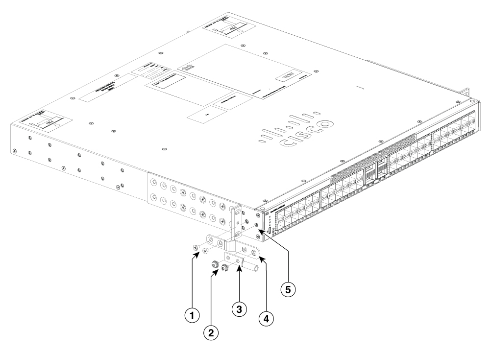
Figure 10. Attaching the grounding lug onto a IRU switch
1
2 counter sunk M4 x 0.6 screws to secure the grounding lug to the chassis
4
Chassis grounding bracket
2
2 M4 x 0.6 pan-head screws to secure the grounding lug to the grounding bracket
5
Location on the switch where the grounding lug is attached
3
Chassis grounding lug
-
-
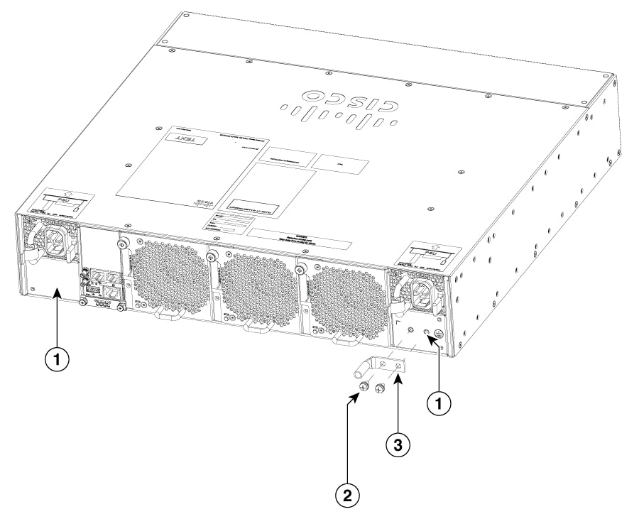
Figure 11. Attaching the grounding lug onto a 2RU switch
1
Location on the switch where the grounding lug is attached
3
Chassis grounding lug
2
2 M4 x 0.6 pan-head screws to secure the grounding lug to the grounding bracket
-
-
3.
Secure the grounding lug to the chassis grounding pad screws. Tighten the screws to 11 to 15 in-lb (1.24 to 1.69 N m) of torque.
For IRU switches, the grounding lug is secured to the chassis grounding pad with four M4 screws. And for 2RU switches the grounding lug is secured with two M4 screws.
4.
Prepare the other end of the grounding wire and connect it to the facility ground.
Post install procedure
This section describes the post installation checks to be done on your switch.
Configure the switch using the Web User Interface. For more information, refer to "Configuring the switch using the Web User Interface" topic in the Software Configuration Guide.
Connect the required devices to the switch ports.
Turn on the power supply switches to power up the system. While powering up, the switch performs a series of bootup diagnostic tests.
Note
The switch is designed to boot up in less than 30 minutes, provided that the neighboring devices are in fully operational state.
Verify port connectivity after connecting devices to the switch ports. The LED turns green when the switch and the attached device have a link.