Describes fan installation guidelines and how to remove and reinsert fans in the C9550 Series Smart switches.
This section provides information about
-
fan installation guidelines and
-
remove and reinsert fans while the switch is operational.
Cisco C9550 Series Smart Switches Hardware Installation Guide
Describes fan installation guidelines and how to remove and reinsert fans in the C9550 Series Smart switches.
This section provides information about
fan installation guidelines and
remove and reinsert fans while the switch is operational.
Observe these guidelines when removing or installing a fan module.
Do not force the fan module into the slot. This can damage the pins on the switch if they are not aligned with the module.
A fan module that is only partially connected to the switch can disrupt the system operation.
The switch supports hot swapping of the fan module. You can remove and replace the module without interrupting normal switch operation.
The procedure to remove and reinsert the 1RU and 2 RU fans are different. This section provides instructions on how to remove and reinsert C9550-FAN-1U fans in your Cisco C9550 Series Smart switches. The C9550-FAN-1U fans are supported by the Cisco C9550 1RU switch models.
| 1. | To remove a fan module, press the ejector levers inward. |
|
| 2. | Pull the fan module and slide it out of the slot.
|
|
| 3. | Align the fan module along the fan slot and firmly push it into the slot, applying pressure to the end of the module. When correctly inserted, you can hear a click, and the fan module is flush with the switch rear panel. When the fan is operating, the status LED on the top left corner of the fan module will glow green. 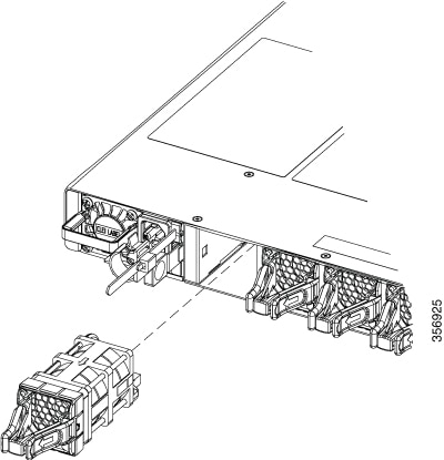
|
The procedure to remove and reinsert the 1RU and 2 RU fans are different. This section provides instructions on how to remove and reinsert C9550-FAN-2U fans in your Cisco C9550 Series Smart switches. The C9550-FAN-2U fans are supported by the Cisco C9550 2RU switch models.
| 1. | To remove a fan module, loosen the screw on the top left corner of fan module. You cannot remove the screw from the module. |
|
| 2. | Holding the handle, pull the fan module and slide it out of the slot.
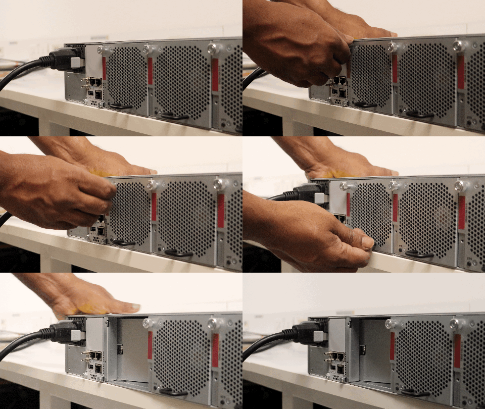
To view the animation, click this link. |
|
| 3. | To insert a fan module, align the fan module along the fan slot and firmly push it into the slot, applying pressure to the end of the module. When correctly inserted, the fan module is flush with the switch rear panel. |
|
| 4. | Tighten the screw on the fan module. When the fan is operating, the status LED on the bottom left corner of the fan module will glow green. 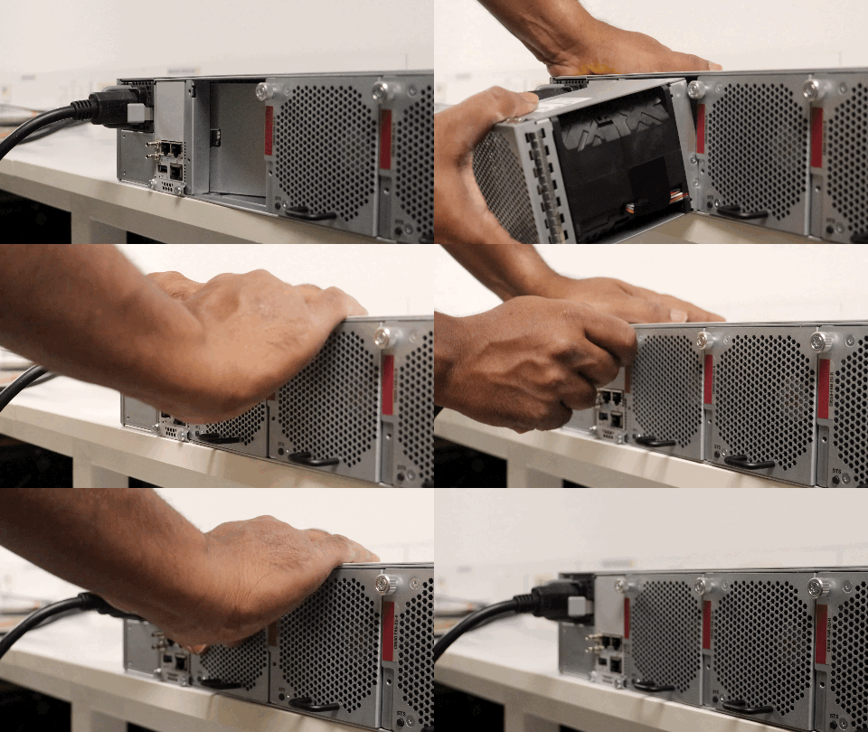
To view the animation in PDF, click this link. |