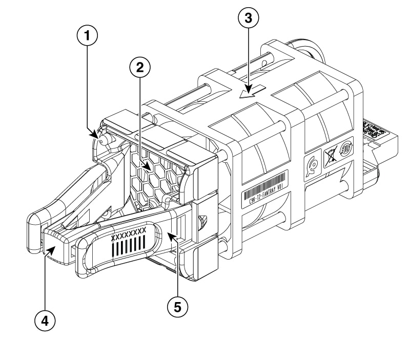
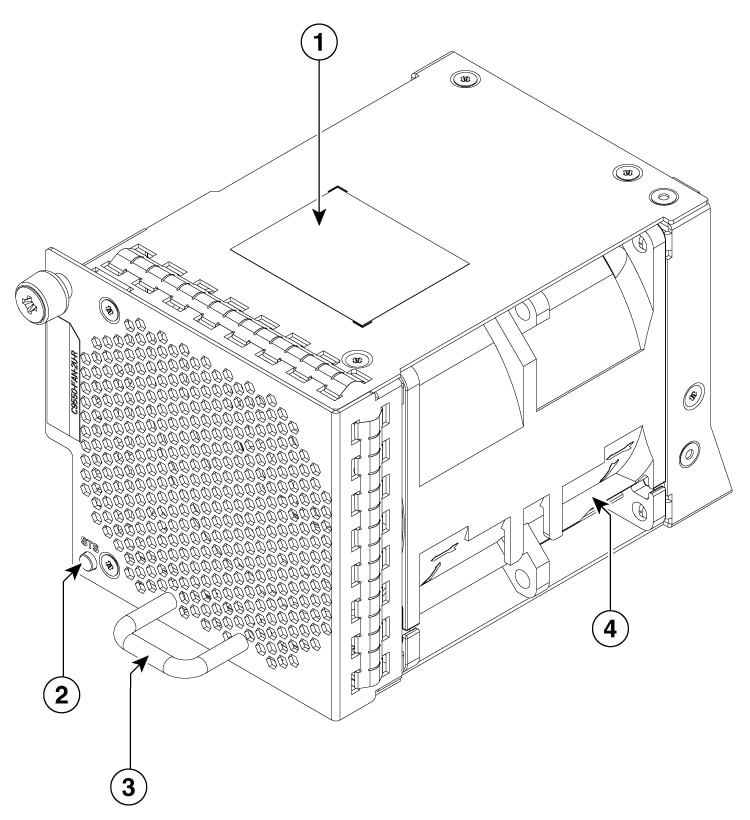
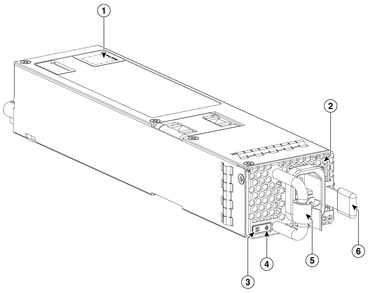
Describes the rear-panel components of C9550 Series Smart switches.
The rear panel of C9550 Series Smart switches include fans and power supply modules.
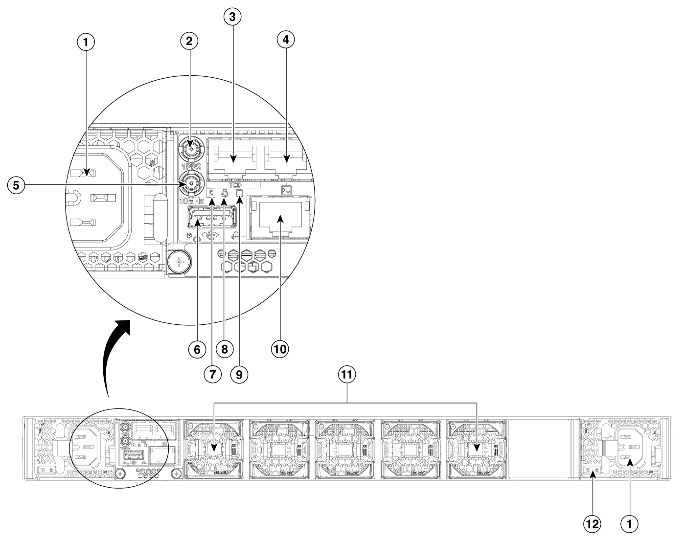
| 1 |
Power supply units (PSUs) When viewed from the rear, PSU0 is on the right side and PSU1 on the left side. |
7 |
Status LED |
| 2 |
1PPS (I/O) DIN port |
8 |
Blue beacon |
| 3 |
TOD PTP RJ-45 port |
9 |
M2 SSD LED |
| 4 |
RJ-45 console port |
10 |
RJ-45 management port |
| 5 |
10MHz (I/O) DIN port |
11 |
Fan tray assembly When viewed from the rear, fans are numbered from right to left and starts from 1. 0 is reserved for the blank slot. |
| 6 |
USB 3.0 port |
12 |
Power supply LEDs |
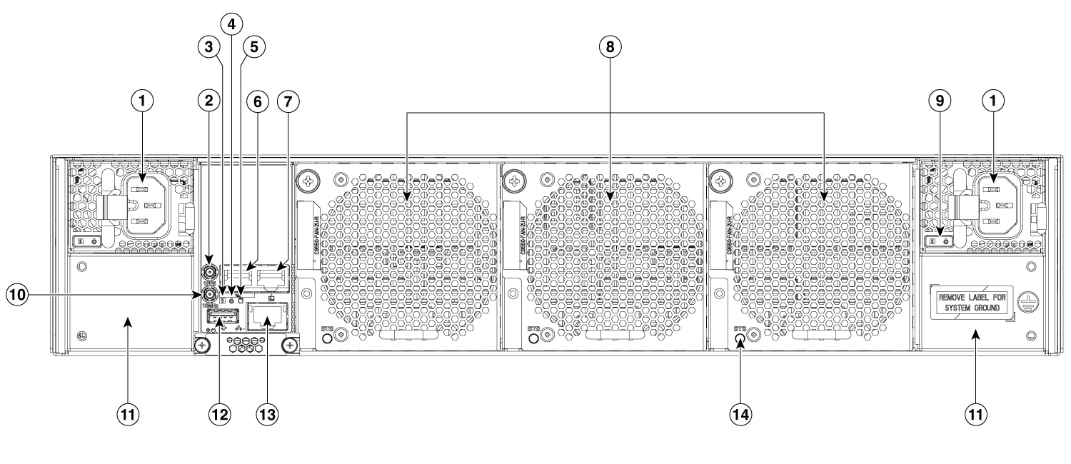
| 1 |
Power supply units (PSUs) When viewed from the rear, PSU0 is on the right side and PSU1 on the left side. |
8 |
Fan tray assembly When viewed from the rear, fans are numbered from right to left and starts from 1. 0 is reserved for the blank slot. |
| 2 |
1PPS (I/O) DIN port |
9 |
PSU LEDs |
| 3 |
Status LED |
10 |
10MHz (I/O) DIN port |
| 4 |
Blue beacon |
11 |
Location for attaching system ground |
| 5 |
M2 SSD LED |
12 |
USB 3.0 port |
| 6 |
TOD PTP RJ-45 port |
13 |
RJ-45 management port |
| 7 |
RJ-45 console port |
14 |
Fan LED |