Cisco C9550 Series Smart Switches Hardware Installation Guide

PDF

Cisco C9550 Series Smart Switches Hardware Installation Guide

Install and remove power supply units

Want to summarize with AI?

Log in

Describes how to remove and reinstall a power supply module and connect to an AC and DC power source.


This section provides information about

  • Guidelines to install power supply units

  • Removing power supply units

  • Installing power supply units

  • Connect to an AC power source

  • Connect to a DC power source.

Connect to a power source

Each power cable is shipped with mating connectors with one of the connectors on the power socket and the other connector on the front panel of the power supply. You follow the same steps to install the AC-input and DC-input power supplies, but you must ground them differently.

  • AC-input power supply—It is automatically grounded when you connect its power cable to the power supply and the power source.

  • DC-input power supply—You do not connect the power supply directly to the earth ground.

You use one power cord for each power supply to connect the power supply to its power source.

Power supply install guidelines

The switch chassis must be installed in a cabinet or rack that is secured to the data center.

  • Remove the power supply from its shipping container and remove any packaging.

  • You need the following additional tools and equipment.

    • Nut driver attachment for number 1 Phillips-head screwdriver or ratchet wrench with torque capability (used only for DC-input power supplies).

    • Grounding wire—Size this wire to meet local and national installation requirements. For U.S. installations, you must use an 8-14 AWG copper conductor for AC power supply systems. For installations outside the U.S., consult your local and national electrical codes. The length of the grounding wire depends on the proximity of the switch to proper grounding facilities.

  • The chassis is connected to an earth ground.

  • Receptacles are available for the power sources within reach of the power supply cables.

  • When connecting to DC power, check that you are using the correct power cables to connect to the power supply. The wire size applies to the negative [-], and positive [+] cables that connect to negative and positive apertures on the connector. You have to procure the power cable.

  • If you are installing more than one DC-input power supply, each must be protected by a dedicated circuit breaker or a fuse that is sized according to the power supply input rating and the local or national electrical code requirements.

  • The power sources are rated as follows:

    • For North American AC-input installations: 20A with 120V circuits.

    • For North American DC-input installations: –48 VDC nominal at 50 A in North America (operating range: –40.5 to –56 VDC).

    • For international installations—Size the circuits by local and national standards.

Caution

Ensure that the power source is OFF. As an added precaution, place the appropriate safety flag and lockout devices at the source power circuit breaker to prevent accidental power restoration while you are working on the circuit.

Warning

Statement 1028—More Than One Power Supply

This unit might have more than one power supply connection. To reduce risk of electric shock, remove all connections to de-energize the unit.

Warning

Statement 1003—DC Power Disconnection

To reduce risk of electric shock or personal injury, disconnect DC power before removing or replacing components or performing upgrades.

Warning

Statement 1046—Installing or Replacing the Unit

To reduce risk of electric shock, when installing or replacing the unit, the ground connection must always be made first and disconnected last.

If your unit has modules, secure them with the provided screws.

Warning

Statement 1024—Ground Conductor

This equipment must be grounded. To reduce the risk of electric shock, never defeat the ground conductor or operate the equipment in the absence of a suitably installed ground conductor. Contact the appropriate electrical inspection authority or an electrician if you are uncertain that suitable grounding is available.


Remove power supply units

Procedure

1.

Turn off the power to the power supply that you are removing.

If you are removing a DC-input power supply, ensure that the power is turned off at the power source by turning off the power for that circuit.

2.

Detach the power and ground cables.

  • For the AC-input power supply, unplug the power cables that are attached to the power supply and the power source.

  • For the DC-input power supply, remove the power cables from the power supply and the power source.

3.

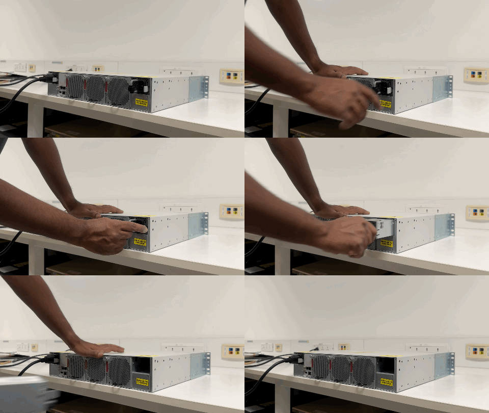
To remove the power supply from the chassis, press the ejector latch on the right side of the power supply unit.

Figure 1. Remove a power supply unit
Remove a PSU

To view the animation in PDF, click this link.

4.

Pull the power supply out of the slot by its handle.

Caution
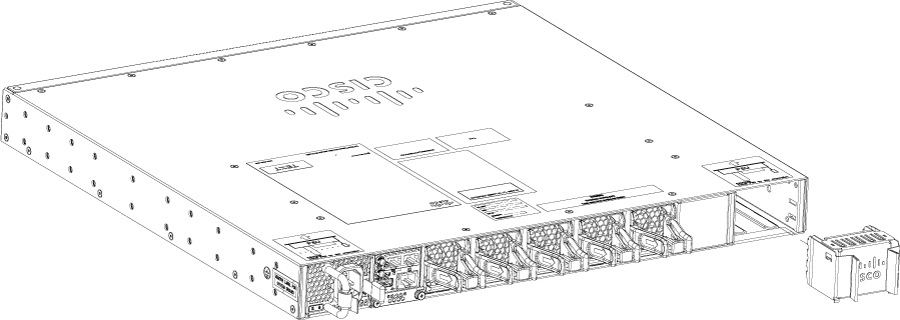
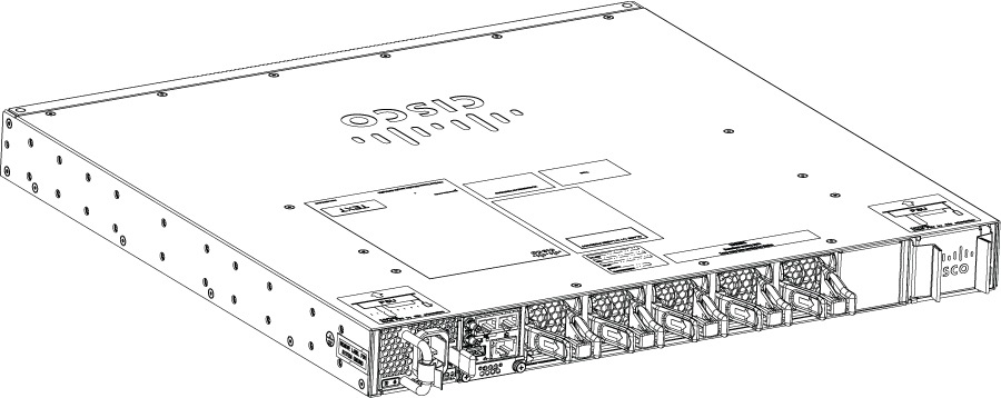
If you intend to operate the switch without installing another power supply in the empty slot, you must install a blank cover over the empty power supply slot to ensure proper air flow in the system and for safety reasons.
Figure 2. Switch with PSU blank not installed
PSU blank not installed
Figure 3. Switch with PSU blank installed
PSU blank installed

Insert power supply units

Procedure

1.

Remove the blank cover and store it for future use.

2.

Verify that the power supply is not connected to any power sources.

3.

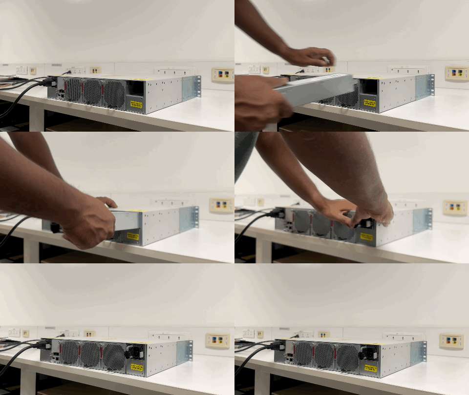
Hold the handle on the power supply with one hand and position the power supply with its back end at the open power supply bay.

Figure 4. Insert the power supply unit
Insert a PSU

To view the animation in PDF, click this link.

4.

Slide the unit all the way into the power supply bay until the release latch on the right side of the power supply clicks into place and prevents you from moving the power supply in or out of the chassis.

Ensure that the power supply in inserted into the slot in the right direction. If you have inserted the power supply in the reverse direction, the amber LED on the power supply blinks continuously.


Connect to an AC power source

Procedure

1.

Prior to connecting the power supply to a power source, ensure that the chassis is properly grounded.

2.

Plug the power cable into the power supply.

3.

Plug the other end of the power cable into a power source supplied by the data center.

Note

When using redundant mode, connect each power supply to a separate power source.

Verify that the power supply is receiving power by checking the power supply LEDs. For more information about the power supply LEDs and the conditions that they indicate, refer to the Power supply LEDs section.


Connect to a DC power source

Perform this task to connect a DC power supply directly to one or two DC power sources.

Warning

Statement 1033—Safety Extra-Low Voltage (SELV)—IEC 60950/ES1–IEC 62368 DC Power Supply

To reduce the risk of electric shock, connect the unit only to a DC power source that complies with the SELV requirements in the IEC 60950-based safety standards or the ES1 requirements in the IEC 62368-based safety standards.

Procedure

1.

Prior to connecting the power supply to a power source, ensure that the chassis is properly grounded.

2.

Turn off the power at the circuit breakers for portions of the DC grid power that you are connecting to and verify that all the LEDs on the DC grid power supplies are off.

3.

Plug the DC power cable into the DC power supply.

4.

Attach the cable to the output of the power source.

For the PWR-2KW-DC-CBL cable, pin 1 of the Amphenol connector is attached to the red cable, and pin 2 is attached to the black cable. Connect the black cable to +DC terminal at the PSU side, which is the battery (positive/+) terminal.

Connect the green or yellow lead to the rack ground or building earth ground to ensure proper grounding of the switch, before powering it on.

5.

Verify that the power supply is receiving power by checking that the LED is on and the color is green. For more information about the power supply LEDs and the conditions they indicate, refer to the Power supply LEDs section.

When you first activate the power supply, if the LED is flashing amber or red, check the power connections on the power supply and the power source.