Preparing for Installation
Available Languages
Table Of Contents
Cisco Professional Installation
Site Environmental Requirements
Electrical Service Requirements
Electrical Circuit Requirements
Asynchronous Terminal Connections
Setting Up Fiber-Optic Connections
Rack-Mounting and Location Guidelines
Preventing Electrostatic Discharge Damage
Receiving the Cisco 10005 Series Router
Specifications for Cisco 10005 Power Modules
Power Guidelines for DC Systems
Verifying Contents After Unpacking
Preparing for Installation
Read this chapter before you install the Cisco 10005 router. It include site preparation information including electrical requirements for the system, environmental and space requirements your installation site must meet to maintain normal operation, safety guidelines, and an overview of the installation process.
Do not unpack the system until you are ready to install it. Keep the chassis in the shipping container to prevent accidental damage until you identify and prepare an installation site.
The following sections are in this guide:
•
Verifying Contents After Unpacking
Hardware Overview
The Cisco 10005 chassis is structured as follows:
•
•
•
•
•
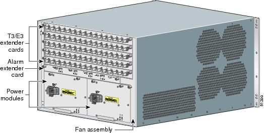
Figure 1-1 and Figure 1-2 show a fully loaded chassis with redundant PREs, redundant AC power supplies, a fan assembly, and five line cards.
Figure 1-1 Cisco 10005 Chassis—Front View
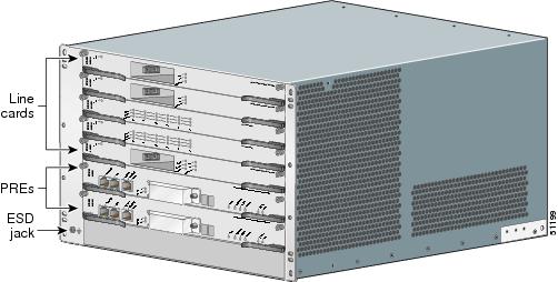
Figure 1-2 Cisco 10005 Chassis—Rear View
Site Planning
This section contains site planning information, and will help you plan for the installation of the Cisco 10005 router. It contains the following sections:
•
•
•
•
Cisco Professional Installation
Professional installation of the Cisco 10000 series router is available through the Cisco Professional Services group. This includes advance site planning, configuring the router to your requirements, and testing the installed system.
For more information about professional installation, talk to your Cisco sales representative.
Site Selection Guidelines
The Cisco 10000 series router requires specific environmental operating conditions. Temperature, humidity, altitude, and vibration can affect the performance and reliability of the router. The following sections provide specific information to help you plan for the proper operating environment.
Site Environmental Requirements
Environmental monitoring in the Cisco 10000 series router protects the system and components from damage caused by excessive voltage and temperature conditions. To ensure normal operation and avoid unnecessary maintenance, plan and prepare your site configuration before installation. After installation, make sure the site maintains the environmental characteristics as shown in Table 1-1.
Heat Dissipation
Like all electronic equipment, the Cisco 10000 series router chassis and components produce heat when turned on and operating. You must assess the site's air conditioning capacity, and ensure it can compensate for the heat dissipation of the system. Table 1-2 shows the maximum BTUs dissipated by the Cisco 10005 chassis with an AC PEM and all line cards installed.
Table 1-2 Heat Dissipation of Cisco 10005 Series Router
Cisco 10005
4095 Btu/hr
Physical Characteristics
Be familiar with the physical characteristics of the Cisco 10000 series router to assist you in placing the system in the proper location. Table 1-3 shows the weight and dimensions of the Cisco 10005 router chassis.
Floor Loading Considerations
Ensure that the floor under the rack supporting the Cisco 10005 series router is capable of supporting the combined weight of the rack and all other installed equipment.
To assess the weight of the fully configured Cisco 10005 chassis, refer to Table 1-3.
For additional information about floor loading requirements, consult the document GR-63-CORE, Network Equipment Building System (NEBS) Requirements: Physical Protection.
Site Power Requirements
The Cisco 10005 series router has specific power and electrical wiring requirements. Adhering to these requirements ensures reliable operation of the system. The following sections specify the electrical service and circuit requirements.
Electrical Service Requirements
The building's electrical wiring supplying power to the Cisco 10005 series router must comply with all applicable building electrical codes. Also, the installation must comply with the following requirements:
•
•
•
•
•
•
Electrical Circuit Requirements
Each Cisco 10005 series router requires a dedicated electrical circuit. If you equip it with dual power feeds, provide a separate circuit for each PEM to avoid compromising the power redundancy feature.
The Cisco 10005 series router can be powered by a DC or AC source. Ensure the equipment grounding is in compliance with local and national electrical codes.
The following sections contain specific recommendations for AC and DC powered systems.
AC Powered Systems
The AC Power Supply of the Cisco 10005 router chassis has an IEC 320 C20 male AC inlet connector, which mates to an AC power cord with an IEC 320 C19 connector on one end, and a connector compatible with the building's AC receptacle on the other end. When you order the chassis, you must specify the type of connector you need to ensure compatibility with the building's AC receptacle.
The electrical ratings of the Cisco 10005 router AC power supply are:
•
–
–
•
•
DC Powered Systems
The DC PEMs for the Cisco 10005 router chassis are not shipped with wiring to connect to the DC source. Both systems have terminal blocks to attach building's input, return, and earthing (ground) wiring. The DC power source must comply with the Safety Extra Low Voltage (SELV) requirements in IEC 60950 based safety standards.
The electrical ratings of the DC PEMs for both the Cisco 10005 chassis are:
•
–
–
•
•
Site Cabling Guidelines
This section contains guidelines for wiring and cabling at your site. When preparing your site for network connections to the Cisco 10005 series router, consider the type of cable required for each line card, and the cable's limitations. Possible cable types are fiber, thick or thin coaxial, foil twisted-pair, or unshielded twisted-pair cabling.
Also consider any additional interface equipment you need, such as transceivers, hubs, switches, modems, channel service units (CSUs), or data service units (DSUs).
Before you install the Cisco 10005 series router, have all additional external equipment and cables on hand. For ordering information, contact a customer service representative.
Asynchronous Terminal Connections
The PRE provides a Console Port to connect a terminal or computer for local console access. The PRE also provides an Auxiliary Port to connect to a modem for remote dial-in console access.
Both ports have RJ-45 connectors, support RS-232 asynchronous data, and have distance recommendations specified in the IEEE RS-232 standard.
Ethernet Connections
The distance you can extend your networks or the distances between them depends on the type of signal, signal speed, and transmission media used. The following sections detail recommendations for Ethernet connections.
Ethernet and Fast Ethernet over Twisted-Pair
Ethernet (10BaseT) and Fast Ethernet (100BaseT) signaling is typically over twisted-pair cabling. The IEEE has specific distance limitations detailed in IEEE standard 802.3, but industry experience has shown that connections remain reliable at speeds and distances far greater than these. If you choose to exceed the distances and speeds recommended by the IEEE, you do so at your own risk.
Table 1-4 shows the distance limits for Ethernet 10BaseT and 100BaseT signal types over twisted-pair cabling.
Setting Up Fiber-Optic Connections
For other fiber-optic specifications, see the Cisco 10000 Series Routers Line Card Hardware Installation Guide.
Interference Considerations
When wires are run for any significant distance, there is a risk that stray signals will be induced on the wires as interference. If interference signals are strong, they can cause data errors or damage to the equipment.
The following sections describe sources of interference and how to minimize its effects on the Cisco 10005 series router.
Electromagnetic Interference
All equipment powered by AC current can propagate electrical energy that can cause electromagnetic interference (EMI) and possibly affect the operation of other equipment. The typical sources of EMI are equipment power cords and power service cables from electric utility companies.
Strong EMI can destroy the signal drivers and receivers in the Cisco 10005 series router and even create an electrical hazard by causing power surges through power lines into installed equipment. These problems are rare, but could be catastrophic.
To resolve these problems, you need specialized knowledge and equipment, which could consume substantial time and money. However, you should ensure that you have a properly grounded and shielded electrical environment, paying special attention to the need for electrical surge suppression.
Radio Frequency Interference
When electromagnetic fields act over a long distance, radio frequency interference (RFI) can be propagated. Building wiring can often act as an antenna, receiving the RFI signals and creating more EMI on the wiring.
If you use twisted-pair cable in your plant wiring with a good distribution of grounding conductors, the plant wiring is unlikely to emit radio interference. If you exceed the recommended distances, use a high-quality twisted-pair cable with one ground conductor for each data signal.
Lightning and AC Power Fault Interference
If signal wires exceed recommended cabling distances, or if signal wires pass between buildings, you should consider the effect that a lightning strike in your vicinity might have on the Cisco 10005 series router.
The electromagnetic pulse (EMP) generated by lightning or other high-energy phenomena can couple enough energy into unshielded conductors to damage or destroy electronic equipment. If you have previously experienced such problems, you should consult with RFI/EMI experts to ensure that you have adequate electrical surge suppression and shielding of signal cables in your Cisco 10005 series router operating environment.
Rack-Mounting and Location Guidelines
The sections that follow describe criteria for selecting a rack to mount the Cisco 10005 series router, and guidelines for placing the rack for reliable operation.
Rack Selection Guidelines
We recommend that you mount the Cisco 10005 series router in an equipment rack, and includes the necessary rack-mounting hardware which is suitable for most 19-inch equipment and Telco-type racks.
Consider installing the Cisco 10005 series router in a rack with the following features:
•
•
•
•
Rack Configuration Guidelines
Several rack-mounting configurations are possible to provide maximum density. The following sections describe mounting configurations for the Cisco 10005 chassis.
Cisco 10005 Chassis
You can mount six Cisco 10005 chassis in a standard 7-foot-high rack, with 3 inches between each rack for wiring management. The 10005 chassis can be flush mounted, or mid-mounted to bring the front of the chassis 6 inches out from the mounting rails.
Bracket Extenders are required to mid-mount the Cisco 10005 chassis in a 23-inch Telco rack. For more information on mid-mounting, see "Mounting in a 23-Inch Rack" section.
Rack Placement Guidelines
The placement of the rack can affect personnel safety, system maintenance, and the system's ability to operate within the environmental characteristics described in Table 1-1. Choose a proper location for the Cisco 10005 series router by following the guidelines below.
Locating for Safety
If the Cisco 10005 series router is the heaviest, or the only piece of equipment in the rack, consider installing it at or near the bottom to ensure that the rack's center of gravity is as low as possible.
For additional information about the proper placement of electronic equipment, consult the document GR-63-CORE, Network Equipment Building System (NEBS) Requirements: Physical Protection.
Locating for Easy Maintenance
Keep at least 3 feet of clear space in front and behind the rack. This space ensures that you can remove the Cisco 10005 series router cards and perform routine maintenance and upgrades easily.
Avoid installing the Cisco 10000 series router in a congested rack, and consider how the routing of cables from other pieces of equipment in the same rack could affect access to the routers cards.
Locating for Proper Airflow
Ensure the location of the Cisco 10005 series router has enough airflow to keep the system operating within the environmental characteristics described in Table 1-1, and the air temperature is sufficient to compensate for the heat dissipated by the system as specified in Table 1-2.
Avoid locating the Cisco 10005 series router in a location in which the chassis air intake vents could draw in the exhaust air from adjacent equipment. Consider how the air flows through the Cisco 10005 series router, and be aware that the airflow of the Cisco 10005 chassis is different as described in the following sections.
Cisco 10005 Chassis Airflow
The Cisco 10005 chassis draws cooling air in through the intake vents on the right side of the chassis and moves the air across the internal components and out the exhaust vents on the left side of the chassis, as illustrated in Figure 1-3.
Figure 1-3 Cisco 10005 Chassis Airflow
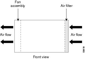
To ensure adequate airflow and prevent overheating inside the chassis, ensure both sides of the Cisco 10005 chassis remain unobstructed. We recommend allowing 3 inches of air space on each side of the chassis.
Site Planning Checklist
Table 1-5 is provided to help you perform and account for all the site planning tasks presented in this appendix.
Table 1-5 Site Planning Checklist
The site meets the environmental requirements (Site Environmental Requirements).
The site's air conditioning system can compensate for the heat dissipation of the Cisco 10000 series (Heat Dissipation).
The floor space that the Cisco 10000 series router occupies can support the weight of the system (Floor Loading Considerations).
Electrical service to the site complies with the requirements (Electrical Service Requirements).
The electrical circuit servicing the Cisco 10000 series router complies with the requirements (Electrical Circuit Requirements).
Consideration has been given to the console port wiring, and limitations of the cabling involved, according to TIA/EIA-232F (Asynchronous Terminal Connections).
The Cisco 10000 series routers ethernet cabling distances are within limitations (Ethernet Connections).
The Cisco 10000 series routers fiber optic cable distances are within limitations (Interference Considerations).
Interference Considerations have been studied, and an EMI/RFI expert has been consulted if necessary.
The equipment rack in which you plan to install the Cisco 10000 series router complies with requirements (Rack Selection Guidelines).
Careful consideration has be given to safety, ease of maintenance, and proper airflow in selecting the location of the rack (Rack Placement Guidelines).
Safety Guidelines
When you install the Cisco 10005 router, observe all of the caution and warning statements in the installation procedures. For warning translations, refer to the Regulatory Compliance and Safety Information for the Cisco 10000 Series Routers.
Read the following guidelines to help ensure your safety and protect the equipment. These guidelines may not cover all potentially hazardous situations you may encounter during system installation, so be alert.
•
•
•
•
•
•

Warning
Statement 49
Preventing Electrostatic Discharge Damage
Electrostatic discharge (ESD) damage, which occurs when electronic cards or components are improperly handled, can result in complete or intermittent failures. The performance routing engine (PRE) card and all line cards consist of one or more printed circuit cards that are fixed in a metal carrier. Electromagnetic interference (EMI) shielding and connectors are integral components of the carrier. Although the metal carrier helps to protect the cards from ESD, use an antistatic strap each time you handle the cards. Handle the carriers by the edges only; never touch the cards or connector pins.

Caution
Following are guidelines for preventing ESD damage:
•
•
Figure 1-4 ESD Chassis Connection
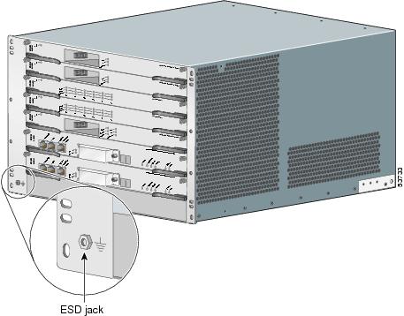
•
•
Caution
Electrical Safety
All system components are hot-swappable. They are designed to be removed and replaced while the system is operating without presenting an electrical hazard or damage to the system.
Follow these basic guidelines when you are working with any electrical equipment:
•
•
•
•
•
•
In addition, use the guidelines that follow when working with any equipment that is connected to telephone wiring or other network cabling—even if that equipment is disconnected from its power source.
•
•
•
•
Warning
Warning
Warning
Receiving the Cisco 10005 Series Router
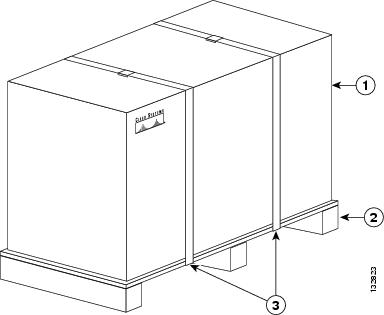
Each Cisco 10000 series router chassis is shipped in a container that is strapped to a pallet as illustrated in Figure 1-5, and includes the physical dimensions listed in Table 1-6.
Table 1-6 Shipping Dimensions and Weight of Cisco 10000 Series Router
10005
26 in. (66 cm)
33 in. (84 cm)
25 in. (63.5 cm)
Figure 1-5 Cisco 10000 Series Router Packaged for Shipping
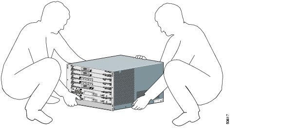
After you receive the Cisco 10000 series router, we recommend that you have three people available to help with the installation and ensure safe lifting.
Chassis-Lifting Guidelines
The fully configured system weighs approximately 140 pounds (63.6 kg). The chassis is not intended to be moved frequently. Before you install the system, ensure that your site is properly prepared so you can avoid moving the chassis later to accommodate power sources and network connections.
Two or more people are required to lift the chassis. Each time you lift the chassis or any heavy object, follow these guidelines:
•
•
•
•
•
•
•
To safely lift the chassis, perform the following steps:
Warning
Figure 1-6 Lifting the Chassis
Step 1
Step 2
Specifications for Cisco 10005 Power Modules
Table 1-7 lists the specifications for DC and AC power modules.
Power Guidelines for DC Systems
The DC-input power supply allows the Cisco 10005 router to operate at -48 VDC nominal in North America and at -48 VDC or -60 VDC in Europe.
See Table 1-7 for system power specifications, including input voltage and operating frequency ranges.
Warning
Statement 1022
Follow your local and national electrical codes for DC wiring.
Environmental Guidelines
This section summarizes space and temperature requirements for the Cisco 10005 router. For a complete discussion of environmental requirements, refer to "Site Selection Guidelines" section.
The Cisco 10005 router is an FCC Class B device. For a complete listing of regulatory compliance information, see the Regulatory Compliance and Safety Information for the Cisco 10000 Series Routers, a document available on Cisco.com.
Both sides of the chassis must remain unobstructed to ensure adequate airflow and prevent overheating inside the chassis. We recommend that you allow 3 inches (7.6 cm) of air space on each side of the chassis. The fans draw in cooling air through the intake vents on the right side of the chassis, move the air across the internal components, and blow it out the exhaust vents on the left side of the chassis (Figure 1-7).
Allow the following unobstructed space around the chassis for air flow and for normal system maintenance tasks, such as cleaning the air filter and replacing or rearranging field-replaceable units (FRUs):
•
•
•
•
After installation, maintain the site at an ambient temperature of 41°F to 104°F (5°C to 40°C). (The system can operate for short periods at up to 131×F (55×C).)
Keep the area around the chassis as free from dust as possible. Change or clean the chassis air filter regularly.
Figure 1-7 Cooling Air Path
Verifying Contents After Unpacking
Power cables, manuals, and other items are packaged in separate boxes. After you have unpacked the system, verify that you have received all of the required components. Using the packing list as a guide, take the following steps to check the contents of the Cisco 10005 shipping container:
Step 1
•
•
Step 2
Installation Road Map
Make sure that your installation follows this sequence:
1.
2.
•
3.
4.
•
•
5.
6.
•
•
7.
8.
9.
 Feedback
Contact Cisco
- Open a Support Case

- (Requires a Cisco Service Contract)
This Document Applies to These Products
- Collaboration Endpoints - Retired Products
- Conferencing - Retired Products
- Contact Center - Retired Products
- Optical Networking - Retired Products
- Routers - Retired Products
- Security - Retired Products
- Servers - Unified Computing (UCS) Retired Products
- Storage Networking Retired Products
- Switches - Retired Products
- Video - Retired Products
- Wireless - Retired Products