Table Of Contents
General Rack Installation Guidelines
Flush-Mounting in a 19-Inch Rack
Five-Inch Mounting in a 19-Inch Rack
General Tabletop or Workbench Installation
Rack and Nonrack Installation
This chapter describes how to install the Cisco 10005 router in an equipment rack or cabinet or on an equipment shelf or a tabletop.
The following sections are in this chapter:
•
General Tabletop or Workbench Installation
Installation Methods
Although rack-mounting is the preferred method of installing the Cisco 10005 chassis, you can mount the router in an alternate location, such as on an equipment shelf or on a tabletop.
An accessory kit that ships with the Cisco 10005 router contains some of the equipment you need for rack mounting and cable management.
For mounting the chassis in a:
•
19-inch wide (standard), 4-post equipment rack or telco-type equipment rack, use the rack-mount brackets in the kit or the mounting flanges built into the chassis.
•
23-inch wide equipment rack, order bracket extenders to fit the 23-inch rack. (These are not available from Cisco.) See the "Tools and Supplies" section for details on bracket extenders.
For mounting the chassis in either type of rack, you must provide screws that are compatible with your rack.
The cable management bracket relieves the strain on interface cables connected to the back of the chassis. It also helps you arrange interface cables in such a way that the power modules, fan assembly, and air filter can be removed and replaced.
If you are installing the chassis on an equipment shelf, on a tabletop, or if you are using mounting hardware other than that supplied with the chassis, go to the "General Tabletop or Workbench Installation" section.
Rack-Mounting the Chassis
Rack-mounting is the preferred method of installation for the Cisco 10005 router. This section covers the following types of installations:
•
Flush-Mounting in a 19-Inch Rack
•
Five-Inch Mounting in a 19-Inch Rack
General Rack Installation Guidelines
When planning your rack installation, consider the following guidelines:
•
The Cisco 10005 chassis requires a minimum of 7 rack units (12.25 inches or 31.12 cm) of vertical rack space. If you plan to use the rear cable management bracket, allow 8 rack units (14 inches or 35.56 cm). Measure the proposed rack location before mounting the chassis in the rack.
•
Before using a particular rack, check for obstructions (such as a power strip) that could impair rack-mount installation. If a power strip impairs a rack-mount installation, remove the power strip before you install the chassis, and then replace it after the chassis is installed.
•
Allow sufficient clearance around the rack for maintenance:
–
In the front of the chassis—3 to 4 ft (91 cm to 122 cm)
–
At the rear of the chassis—At least 24 inches (61 cm)
•
Maintain a minimum clearance of 3 inches (7.6 cm) on the sides of the chassis for cooling air intake and exhaust. Avoid placing the chassis in an overly congested rack or directly next to another equipment rack; otherwise, the heated exhaust air from other equipment can enter the inlet air vents and cause an overtemperature condition inside the router.
![]()
CautionTo prevent the chassis from overheating, never install a Cisco 10005 router in an enclosed rack or in a room that is not properly ventilated or air conditioned.
•
Always install heavier equipment in the lower half of a rack to maintain a low center of gravity. This practice helps prevent the rack from falling over.
•
Install and use the cable-management brackets included with Cisco 10005 to keep cables organized and out of the way of the line cards, PREs, fan assembly, and power modules. Ensure that cables from other equipment in the rack do not impair access to the cards and components, or require you to disconnect cables unnecessarily to perform equipment maintenance or upgrades.
•
Install rack stabilizers (if available) before you mount the chassis.
•
Provide an adequate chassis ground (earth) connection for your router. (A grounding procedure is provided in the "Connecting the Chassis to Ground" section.)
Flush-Mounting in a 19-Inch Rack
The Cisco 10005 chassis can be mounted in a 19-inch equipment rack so that the front of the chassis is flush with the rack posts.
Tools and Supplies
Before you begin this procedure, obtain the following:
•
Mounting screws suitable for attaching the Cisco 10005 chassis to your rack. We recommend that you use a minimum of four mounting screws.
•
A screwdriver suitable for use with your mounting screws.
Look for these items in the Cisco 10005 accessory kit:
•
One cable management bracket (optional)
•
Three phillips-head screws for the cable management bracket
![]()
Warning
At least three people are required to mount the chassis in the equipment rack: two people are needed to hold the chassis in place while a third person tightens the mounting screws. Statement 252
Ask at least two other people to help you rack-mount the Cisco 10005 router. When you handle the chassis, always follow proper lifting practices as outlined in the "Environmental Guidelines" section.
Rack-Mounting the Chassis
To flush-mount the Cisco 10005 chassis in a 19-inch equipment rack.
Step 1
(Optional) Install a shelf in the rack to support the Cisco 10005 chassis. If you use a shelf, you can perform the installation with only two people.
Step 2
(Optional) Remove the fan assembly and the power modules to make the chassis easier to lift.
Step 3
Lift the chassis into position between the rack posts (requires two people).
Step 4
Mounting flanges are built into the chassis. Align the holes in the mounting flanges with the rack post holes (Figure 2-1) and attach the chassis to the rack (performed by the third person unless the chassis is resting on a shelf).
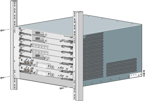
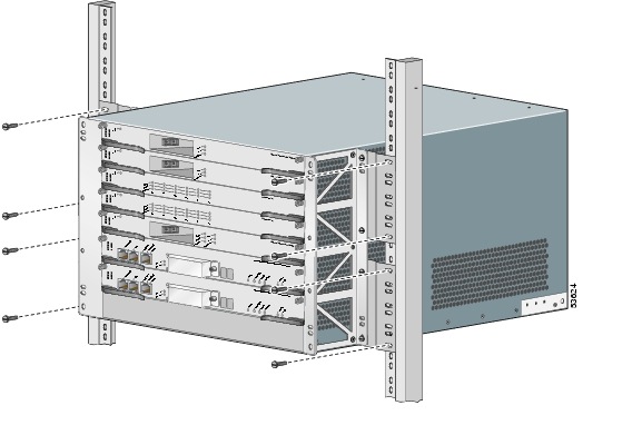
Figure 2-1 Attaching Chassis to Equipment Rack
![]()
Step 5
Attach the cable management bracket to the back of the chassis at the top (Figure 2-2).
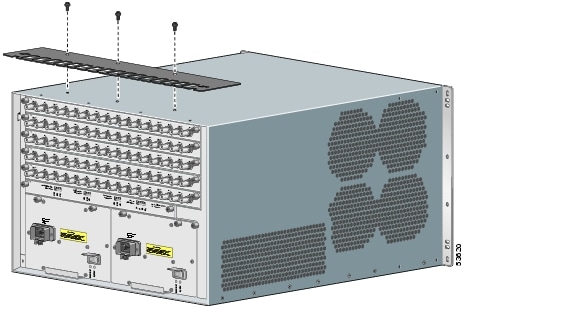
Figure 2-2 Attaching Cable Management Bracket
![]()
Step 6
Check that all
•
Ejector levers on cards are in the closed position.
•
Chassis mounting screws are tight.
•
PRE and line card captive screws are tight.
Step 7
Go to the "Connecting the Chassis to Ground" section to continue the installation.
Five-Inch Mounting in a 19-Inch Rack
The Cisco 10005 chassis can be mounted in a 19-inch equipment rack so that the front of the chassis protrudes about 5 inches from the rack.
Tools and Supplies
Before you begin this procedure, obtain the following:
•
Mounting screws suitable for attaching the Cisco 10005 chassis to your rack. We recommend that you use a minimum of four mounting screws.
•
A screwdriver suitable for use with your mounting screws.
Look for these items in the Cisco 10005 accessory kit:
•
Two mounting brackets
•
Eight screws for the mounting brackets
•
One cable management bracket (optional)
•
Three phillips-head screws for the cable management bracket
Ask at least two other people to help you rack-mount the Cisco 10005 router. When you handle the chassis, always follow proper lifting practices as outlined in the "Environmental Guidelines" section.
![]()
Warning
At least three people are required to mount the chassis in the equipment rack: two people are needed to hold the chassis in place while a third person tightens the mounting screws. Statement 252
Rack-Mounting the Chassis
To mount the Cisco 10005 chassis in a 19-inch equipment rack so that it is set forward 5 inches:
Step 1
Attach the two mounting brackets to the chassis so the flanges (narrow sides with screw holes) are positioned 5 inches back from the front of the chassis (Figure 2-3).
Figure 2-3 Attaching Mounting Brackets to Chassis
![]()
Step 2
(Optional) Remove the fan assembly and the power modules to make the chassis easier to lift.
Step 3
Lift the chassis into position between the rack posts (requires two people).
Step 4
Align the mounting bracket holes with the rack post holes (Figure 2-4) and attach the chassis to the rack (performed by the third person).
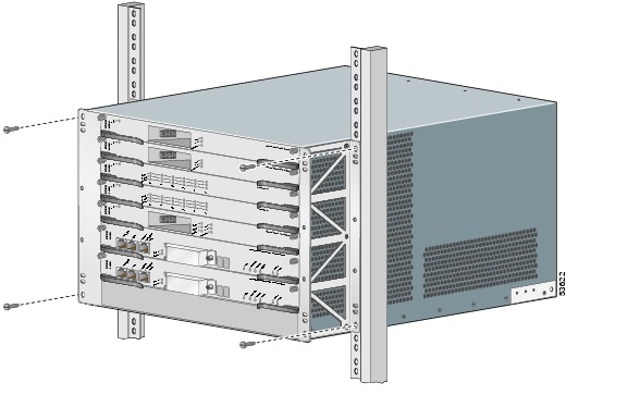
Figure 2-4 Attaching Chassis to Equipment Rack
![]()
Step 5
Attach the cable management bracket to the back of the chassis at the top (Figure 2-5).
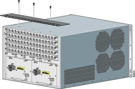
Figure 2-5 Attaching Cable Management Bracket
![]()
Step 6
Check that all
•
Ejector levers on cards are in the closed position.
•
Chassis mounting screws are tight.
•
PRE and line card captive screws are tight.
Step 7
Go to the "Connecting the Chassis to Ground" section to continue the installation.
Mounting in a 23-Inch Rack
The Cisco 10005 chassis can be mounted in a 23-inch equipment rack using bracket extenders that are not provided by Cisco.
Tools and Supplies
Before you begin this procedure, obtain the following:
•
Four bracket extenders (two for each side of the chassis); each should be 3 rack units (5.25 inches or 13.3 cm) high.
•
Eight screws suitable for attaching your bracket extenders to the Cisco 10005 mounting brackets.
•
Mounting screws suitable for attaching the Cisco 10005 chassis to your rack. We recommend that you use a minimum of eight mounting screws.
•
Screwdrivers suitable for use with your screws.
Look for these items in the Cisco 10005 accessory kit:
•
Two mounting brackets
•
Eight screws for the mounting brackets
•
One cable management bracket (optional)
•
Three phillips-head screws for the cable management bracket
Ask at least two other people to help you rack-mount the Cisco 10005 router. When you handle the chassis, always follow proper lifting practices as outlined in the "Environmental Guidelines" section.
![]()
Warning
At least three people are required to mount the chassis in the equipment rack: two people are needed to hold the chassis in place while a third person tightens the mounting screws. Statement 252
Rack-Mounting the Chassis
To mount the Cisco 10005 chassis in a 23-inch equipment rack:
Step 1
Attach the two mounting brackets to the chassis so the flanges (narrow sides with screw holes) are positioned about 5 inches from the front of the chassis, as shown in Figure 2-6.
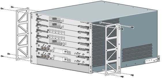
Figure 2-6 Attaching Mounting Brackets to Chassis
![]()
Step 2
Attach the bracket extenders behind the mounting brackets, as shown in Figure 2-7.
Figure 2-7 Attaching Bracket Extenders
![]()
Step 3
(Optional) Remove the fan assembly and the power modules to make the chassis easier to lift.
Step 4
Lift the chassis into position between the rack posts (requires two people).
Step 5
Align the holes in the bracket extenders with the rack post holes (Figure 2-8) and attach the chassis to the rack (performed by the third person).
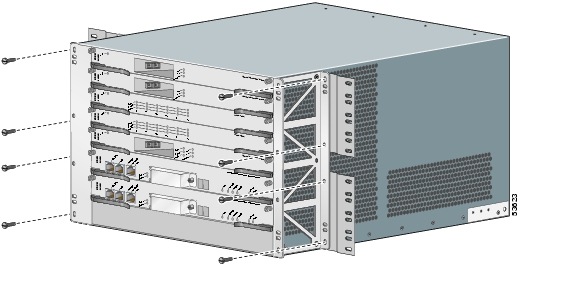
Figure 2-8 Attaching Chassis to Equipment Rack
![]()
Step 6
Attach the cable management bracket to the back of the chassis (Figure 2-9).
Figure 2-9 Attaching the Cable Management Bracket
![]()
Step 7
Check that all
•
Ejector levers on cards are in the closed position.
•
Chassis mounting screws are tight.
•
PRE and line card captive screws are tight.
Step 8
Go to the "Connecting the Chassis to Ground" section to continue the installation.
General Tabletop or Workbench Installation
Move the chassis to the area where you plan to install it. If you have not determined where to install your chassis, see the "Environmental Guidelines" section for information about site considerations.
When installing the Cisco 10005 router on a workbench or tabletop, ensure that the surface is clean and that you have considered the following:
•
The Cisco 10005 router requires at least 3 inches (7.6 cm) of clearance at the inlet and exhaust vents (the left and right sides of the chassis).
•
The Cisco 10005 router should be installed off the floor. Dust that accumulates on the floor is drawn into the interior of the router by the cooling fans. Excessive dust inside the router can cause overtemperature conditions and component failures.
•
There must be approximately 19 inches (48.3 cm) of clearance at the front of the chassis and 24 inches (61 cm) at the rear to install and replace field-replaceable units (FRUs), and to access network cables and equipment.
•
The Cisco 10005 router needs adequate ventilation. Do not install it in an enclosed cabinet.
•
An adequate chassis ground (earth) connection must exist for your router (see the "Connecting the Chassis to Ground" section).
•
Always follow proper lifting practices as outlined in the "Environmental Guidelines" section, when handling the chassis.
Look for these items in the Cisco 10005 accessory kit:
•
One cable management bracket (optional)
•
Three phillips-head screws for the cable management bracket
To install the Cisco 10005 chassis on a tabletop or equipment shelf:
Step 1
Remove any debris and dust from the tabletop or equipment shelf, as well as the surrounding area.
Step 2
Ask someone to help you lift the chassis into position on the tabletop or equipment shelf.
![]()
Warning
Two people are required to lift the chassis. To prevent injury, keep your back straight and lift with your legs, not your back. Statement 164
Step 3
(Optional) Attach the cable management bracket to the back of the chassis (Figure 2-10).
Figure 2-10 Attaching Cable Management Bracket
![]()
Step 4
Check that all
•
Ejector levers on cards are in the closed position.
•
PRE and line card captive screws are tight.
Step 5
Go to the "Connecting the Chassis to Ground" section to continue the installation.