Making Data and Management Connections
Available Languages
Table Of Contents
Making Data and Management Connections
Connecting a Video Terminal to the PRE Console Port
Ethernet Network Management Connections
Connecting to a 10BASE-T Ethernet Network
Connecting to a 100BASE-T Ethernet Network
Making Data and Management Connections
This chapter describes how to connect alarm indicators, a console terminal, a modem, an Ethernet LAN for management, and network data cables to the Cisco 10005 router.
The following sections are in this chapter:
•
Connecting a Video Terminal to the PRE Console Port
•
Connecting Alarm Indicators
The Cisco 10005 router provides relay contacts for optional (customer-supplied) audible or visual alarm indicators. Relay contacts are provided for three levels of severity:
•
•
•
It is not necessary to turn off system power before connecting alarm indicators.
To connect alarm indicators to the system:
Step 1
Figure 4-1 Alarm Panel on Rear of Chassis
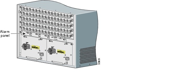
Step 2
a.
b.

Caution
Step 3
Step 4
•
•
In either case, arrange the cables so that you can remove and replace the air filter, the power modules, and the fan assembly.
Connecting a Video Terminal to the PRE Console Port
On the front panel of the PRE is an asynchronous serial (EIA/TIA-232) RJ-45 port labeled Console. You can connect this port to most types of video terminals using the console cable kit that is included with your Cisco 10005 router. The console cable kit contains.
Configure the terminal to these settings:
•
•
•
•
•

Note
For instructions on connecting a console terminal, refer to the Cisco 10005 ESR Hardware Overview and Maintenance Guide, an online document available at Cisco.com.
Auxiliary Modem Connection
You can use the asynchronous EIA/TIA-232 serial port labeled AUX to connect a modem to the PRE for remote administrative access. To connect the Cisco 10005 chassis to a modem.
Step 1
Step 2
Ethernet Network Management Connections
The PRE module provides an Ethernet port that you can connect to a 10BASE-T or 100BASE-T LAN for network management. The Ethernet port is an RJ-45 jack labeled Ethernet.
The subsections that follow list cable specifications and special instructions for each type of Ethernet connection. If you need detailed instructions on how to connect to an Ethernet LAN, refer to the Cisco 10005 ESR Hardware Overview and Maintenance Guide, an online document available at Cisco.com.
Note
Connecting to a 10BASE-T Ethernet Network
To make this connection, you need the following additional equipment (not included):
•
•
–
–
Connecting to a 100BASE-T Ethernet Network
To make this connection, you need the following additional equipment (not included):
•
•
–
–
Caution
The RJ-45 port on the PRE is configurable for 100-Mbps full-duplex or half-duplex operation (half-duplex is the default) and supports IEEE 802.3, Ethernet, and IEEE 802.3u interfaces compliant with 100BASE-T specifications.
Data Network Connections
For network connections for all line cards, see the Cisco 10000 Series Router Line Card Hardware Installation Guide.
 Feedback