Hardware components
The hardware components that enable Routed Optical Networking are:
-
High density routers
-
High capacity pluggable optical modules
-
Optical line systems
Specifications of Cisco 8000 series routers
The Cisco 8000 series routers use Silicon One ASIC to provide full routing functionality. They offer higher capacity and a lower environmental footprint than other available routing silicon.
The Silicon One architecture supports large forwarding tables, deep buffers, flexible packet operations, and enhanced programmability to help you manage complex network requirements.
The 8000 series routers are highly scalable, have deep buffering, and are optimized for 100G, 400G, and 800G. They are also available with additional on-chip High Bandwidth Memory (HBM) to support additional resource scale.
Cisco 8010 series router: PLE service endpoint router
The Cisco 8011-2X2XP4L PLE (Private Line Emulation) Service Endpoint Router (PLE-SER) is a fixed-port router in a one rack unit form factor. It supports 2 x 10G SFP+ PLE, 2 x 10G SFP+ Ethernet, and 4 x 10G, 25G, or 50G SFP56 ports. Private Line Emulation (PLE) enables private line services to be carried over the same IP network for non-Ethernet type services like SONET, SDH, and Fiber Channel.
The PLE client ports support these configuration options:
-
2 x 1G and 10G
-
2 x 10G
-
2 x OTU2
-
2 x OC192 or STM64
-
2 x OTU2e
-
2 x OC48
-
2 x FC-1, 2, 4, 8, or 16G
-
1 x FC-32G (only on port 0)
Cisco 8200 series routers
The Cisco 8200 series uses a single Silicon One ASIC to provide full routing functionality. It is designed for use cases that require high buffering and high scale. These fixed-port and high-density routers provide up to 19.2 Tbps of network bandwidth while consuming significantly less power than comparable 20 Tbps systems.
This table details the specifications of the routers.
| Router | Capacity | Form factor | 400G QSFP-DD ports | 100G QSFP28 ports |
|---|---|---|---|---|
| Cisco 8201 | 10.8 Tbps | 1 rack unit (RU) | 24 | 12 |
| Cisco 8202 | 10.8 Tbps | 2 RU | 12 | 60 |
| Cisco 8201-32FH | 12.8 Tbps | 1 RU |
32 |
– |
|
Cisco 8202-32FH-M |
12.8 Tbps | 2 RU |
32 |
– |
|
Cisco 8201-24H8FH |
5.6 Tbps | 1 RU |
8 |
24 |
Cisco 8800 series routers
The Cisco 8800 series provides high density and efficiency. It provides the extensive scale, buffering, and feature capabilities found in all Cisco 8000 series routers. The 8800 series routers provide up to 260 Tbps through 648 400 GbE ports. The 8800 series includes four chassis options to meet a variety of network and facility requirements.
This table details the specifications of the routers.
| Router | Capacity | Form factor | 400G QSFP-DD ports |
|---|---|---|---|
| Cisco 8804 | Up to 57.6 Tbps | 4-slot, 10 RU |
Up to 144 |
| Cisco 8808 | Up to 115.2 Tbps | 8-slot, 16 RU |
Up to 288 |
| Cisco 8812 | Up to 172.8 Tbps | 12-slot, 21 RU |
Up to 432 |
| Cisco 8818 | Up to 259.2 Tbps | 18-slot, 33 RU |
Up to 648 |
Cisco 8800 series line cards
The Cisco 8800 series modular platform supports 400 GbE line cards for high-speed networking.
This table details the specifications of the routers.
| Line cards | Bandwidth | 400G QSFP-DD ports |
|---|---|---|
| 8800-LC-36FH | 14.4 Tbps | 36 |
| 88-LC0-36FH-M | 14.4 Tbps | 36 |
| 88-LC0-36FH | 14.4 Tbps | 36 |
For information on ZR and ZR+ port support, see Specifications of 400G ZR and ZR+ transceivers.
For more information about Cisco 8000 series routers, see the Cisco 8000 series Routers Data Sheet.
Specifications of Cisco NCS 5500 series routers
The Network Convergence System (NCS) 5500 platform offers high port density, high-performance forwarding, low jitter, and low power consumption.
Cisco NCS-55A2 series fixed port routers
NCS-55A2-MOD-S is a fixed port, high-density, two RU form factor router. It provides 24 SFP or SFP+ ports supporting Gigabit Ethernet or 10-Gigabit Ethernet, and 16 SFP, SFP+, or SFP28 ports supporting Gigabit Ethernet, 10-Gigabit Ethernet, or 25-Gigabit Ethernet. The router supports up to two Modular Port Adapters (MPA).
This table details the specifications of the routers.
| Router | Capacity | Form factor | Nx100G QSFP-DD ports on MPA-2D4H | 100G QSFP28 ports on MPA-4H |
|---|---|---|---|---|
| NCS-55A2-MOD-S | 900Gbps | 2 RU | 8 | 8 |
For more information about Cisco NCS-55A2 series fixed port routers, see the Cisco Network Convergence System 5700 series: NCS-55A2 Fixed Chassis Data Sheet.
Cisco NCS-57B1 series fixed port routers
NCS-57B1-6D24-SYS and NCS-57B1-5DSE-SYS routers provide 4.8 terabits (Tbps) of 400GE or 100GE optimized forwarding capacity. They include QSFP-DD optics, deep packet buffering, full line-rate MACsec, Class C 1588 Precision Time Protocol (PTP), and Synchronous Ethernet (SyncE) in a power-efficient, one RU package.
This table details the specifications of the routers.
| Router | Capacity | Form factor | 400G QSFP-DD ports | 100G QSFP-DD ports |
|---|---|---|---|---|
| NCS-57B1-6D24-SYS | Up to 4.8 Tbps | 1 RU | 6 | 24 |
| NCS-57B1-5DSE-SYS | Up to 4.4 Tbps | 1 RU | 5 | 24 |
For more information about Cisco NCS-57B1 series fixed port routers, see the Cisco Network Convergence System 5700 series: NCS-57B1 Fixed Chassis Data Sheet.
Cisco NCS-57C1 series fixed port routers
NCS-57C1-48Q6D-S is a fixed chassis that combines low port densities of 1GE, 10GE, or 25GE with higher port densities of 50GE, 100GE, or 400GE. It also offers QSFP-DD optics, deep packet buffering, MACsec, Class C 1588 PTP, and SyncE in a power-efficient, one RU package.
This table details the specifications of the routers.
| Router | Capacity | Form factor | 400G QSFP-DD ports | 100G QSFP28 ports |
|---|---|---|---|---|
| NCS-57C1-48Q6-SYS | Up to 2.4 Tbps | 1 RU |
6 Four 400G and two Nx100G ports |
- |
For more information about Cisco NCS-57C1 series fixed port routers, see the Cisco Network Convergence System 5700 series: NCS-57C1 Fixed Chassis Data Sheet.
Cisco NCS-57D2 series fixed port routers
The NCS-57D2-18DD-SYS is a two RU router designed for mass-scale core and aggregation networks. It delivers 7.2 Tbps of 400GE or 100GE optimized forwarding capacity and features high power efficiency, QSFP-DD optics, deep packet buffering, full line-rate MACsec, IPSec, Class C 1588 PTP, and SyncE. The router runs on Cisco IOS XR7. It offers advanced capabilities such as next-generation security, automation, telemetry, segment routing, EVPN, and Equal-Cost Multipathing (ECMP). The router supports 18 ports of 400G and 66 ports of 100G, all with QSFP-DD. Breakout options are available for 10G, 25G, and 100G.
This table details the specifications of the routers.
| Router | Capacity | Form factor | 400G QSFP-DD ports | 100G QSFP28 ports |
|---|---|---|---|---|
| NCS-57D2-18DD-SYS | Up to 7.2 Tbps | 2 RU |
18 |
66 |
For more information about Cisco NCS-57C1 series fixed port routers, see the Cisco Network Convergence System 5700 series: NCS-57C1 Fixed Chassis Data Sheet.
Cisco NCS-57C3 series fixed port routers
The Cisco Network Convergence System 57C3 series routers are designed for cost-effective delivery of next-generation networking services. These routers are high-capacity and low-power consuming devices available in a three RU compact form factor. The chassis, along with the Modular Port Adapters (MPAs), provides options for using different types of interfaces ranging from 1GE to 400GE. It also supports industry-standard MACSec encryption and Class C Timing. These devices also provide Control Plane redundancy, which enables high availability and reliability.
The Cisco NCS 57C3 series routers are suited for a range of applications, including Carrier Ethernet Aggregation, Subscriber Services, Business Ethernet, Mobile Edge, Campus, Peering, and Core roles. The router runs on Cisco IOS XR. It supports a rich and comprehensive set of features like QoS, IP/MPLS, Segment Routing, SRv6, and Ethernet VPN (EVPN).
This table details the specifications of the routers.
| Router | Capacity | Form factor | 400G QSFP-DD ports on MPA-2D4H | 100G QSFP28 ports on base unit |
|---|---|---|---|---|
| NCS-57C3-MOD-S | Up to 2.4 Tbps | 3 RU |
Slot 1 - 4 Nx100G ports, Slot 2 and 3 - two 400G ports or four Nx100G ports |
8 |
| NCS-57C3-MOD-SE | Up to 2.4 Tbps | 3 RU | 4 |
For more information about Cisco NCS-57C1 series fixed port routers, see the Cisco Network Convergence System 5700 series: NCS-57C3 Fixed Chassis Data Sheet.
Cisco NCS 5500 modular chassis
The Cisco NCS 5500 modular chassis series is available in three system sizes: NCS 5504, NCS 5508, and NCS 5516. All NCS systems are highly reliable and resilient platforms. These platforms support a wide range of line card options. NCS 5500 modular router line cards and fabric modules directly attach to each other with connecting pins. In contrast, most traditional modular platform designs require a midplane.
This table details the specifications of the routers.
| Platform | Capacity | Form factor | 400G QSFP-DD ports | 100G QSFP28 ports |
| NCS 5504 | Up to 14.4 Tbps | 4-slot, 7 RU | Up to 96 | Up to 144 |
| NCS 5508 | Up to 76.8 Tbps | 8-slot, 13 RU | Up to 192 | Up to 288 |
| NCS 5516 | Up to 153.6 Tbps | 16-slot, 21 RU | Up to 384 | Up to 576 |
For more information about Cisco Network Convergence System 5500 series modular chassis, see the Cisco Network Convergence System 5500 series Modular Chassis Data Sheet.
NCS 5700 series line cards
NCS 5700 series line cards are 400G line cards for the NCS 5500 series modular chassis. NCS 5700 series line cards consist of two versions of 400GE optimized line cards: the base version and the scale version. The two 400GE optimized line cards in the NCS5700 series are NC57-24DD and NC57-18DD-SE.
The Cisco NCS 5700 series 100G optimized baseline card, NC57-36H6D-S is a combo line card with 4.8-Tbps throughput. NC57-36H6D-S provides a mix of 100GE, 200GE, and 400GE ports. NC57-36H6D-S line card provides flexible port configuration and can be used as 36x100GE or 24x100GE + 12x200GE(2x100GE) or 24x100GE + 6x400GE ports.
The Cisco NCS 5700 series line card, NC57-48Q2D-S, is a high-density line card with a 2.4-Tbps throughput. It provides a mix of 1GE, 10GE, 25GE, 50GE, 100GE, and 400GE ports. The NC57-48Q2D-S line card features 32 SFP28 ports capable of 1/10/25G, 16 SFP56 ports capable of 1/10/25/50G, and 2 QSFP-DD ports supporting 40/100/200/400G with breakout options.
The Cisco NCS 5700 series line card, NC57-48Q2D-SE-S, is a high-density scale edition line card with a 2.4-Tbps throughput. It provides a mix of 1GE, 10GE, 25GE, 50GE, 100GE, and 400GE ports. The NC57-48Q2D-SE-S line card features 32 SFP28 ports capable of 1, 10, or 25G, 16 SFP56 ports capable of 1, 10, 25, or 50G, and 2 QSFP-DD ports supporting 40, 100, 200, or 400G with breakout options. This "Scale Edition" variant includes an external TCAM (OP2) that enables higher prefix and service scale.
For information on ZR and ZR+ port support, see Specifications of 400G ZR and ZR+ transceivers.
For more information about Cisco Network Convergence System 5700 series 400GE, see the Cisco Network Convergence System 5700 series: 400GE and 100GE Line Cards Data Sheet.
NCS 5700 series modular port adapters
The Cisco Network Convergence System 5700 series is designed to efficiently scale between data centers and large enterprises, web, and service provider WAN and aggregation networks. The chassis and line cards support many applications and services through available interfaces. The Modular Port Adapters deliver flexibility to the chassis and line cards. They provide ports with bandwidth up to 400GE and pluggable form factors like QSFP-DD.
NC57-MPA-2D4H-S MPA
NC57-MPA-2D4H-S is a 4-port 800GE modular port adapter (NC57-MPA-2D4H-S) that supports QSFP28 and QSFP-DD optical transceivers. All 4 ports support QSFP28-100GE transceivers. Ports 0 and 2 (even-numbered ports) support two QDD-400G transceivers at the same time. This configuration is supported in both the MPA slots of the NCS-55A2-MOD-HD-S, NC55-55A2-MOD-SE-S, NCS-55A2-MOD-S, or NCS-55A2-MOD-HX-S chassis. Port 0 supports only one QDD-400G transceiver in Nx100G modes in both the MPA slots of the NCS-55A2-MOD-HD-S, NC55-55A2-MOD-SE-S, NCS-55A2-MOD-S, or NCS-55A2-MOD-HX-S chassis.
NC55-OIP-02 MPA
NC55-OIP-02 is an 8-port modular port adapter that supports SFP+ optical transceivers. This MPA is supported in the NC55A2-MOD-S and NC57C3-MOD-SYS routers.
The modular port adapter supports these port modes:
-
Ethernet - 1GE and 10GE
-
Fiber channel (FC) - 1GFC, 2GFC, 4GFC, 8GFC, 16GFC, 32GFC
-
Optical Transport Network (OTN) – OTU2, and OTU2e
-
SONET/SDH - OC-48 or STM-16, OC-192 or STM-64
NC55-OIP-02 MPA is used to support PLE.
For more information about Cisco Network Convergence System 5700 series modular port adapters, see the Cisco Network Convergence System 5700 series: Modular Port Adapters Data Sheet.
Specifications of Cisco ASR 9000 series
The Cisco ASR 9000 series Aggregation Services Routers (ASR 9000 series) introduces a new paradigm in edge and core routing. These routers offer exceptional scalability, carrier-class reliability, environmentally conscious design, flexibility, and a compelling price-to-performance benchmark. The Cisco ASR 9000 series includes a wide range of products, from the Cisco ASR 9001 (two RU) to the Cisco ASR 9922 (44 RU). Each system is designed to provide true carrier-class reliability with the Cisco IOS XR operating system, comprehensive system redundancy, and full network resiliency. Finally, the Cisco ASR 9000 series is designed to enhance and simplify the operational aspects of service delivery network deployment.
The Cisco ASR 9000 series offers advanced switching capacity, optimized power consumption and cooling, high availability design, and a modular operating system to significantly lower the Total Cost of Ownership (TCO) for service providers.
This table details the specifications of the routers.
| Router | Capacity | Form factor | 400G QSFP-DD ports |
|---|---|---|---|
| ASR 9006 | Up to 16 Tbps | 10 RU | Up to 20 |
| ASR 9010 | Up to 32 Tbps | 21 RU | Up to 32 |
| ASR 9904 | Up to 16 Tbps | 6 RU | Up to 8 |
| ASR 9906 | Up to 32 Tbps | 14 RU | Up to 16 |
| ASR 9910 | Up to 64 Tbps | 21 RU | Up to 32 |
| ASR 9912 | Up to 80 Tbps | 30 RU | Up to 40 |
| ASR 9922 | Up to 160 Tbps | 44 RU | Up to 80 |
For more information on Cisco ASR 9000 series, see Cisco ASR 9000 series Aggregation Services Routers Data Sheet.
Cisco ASR 9902 compact router
The Cisco ASR 9902 router is a compact, high-performance device that delivers up to 800 Gbps of nonblocking, full-duplex capacity in a two RU form factor. It uses the same Cisco IOS XR software as other routers in the Cisco ASR 9000 series and provides the same features and services. Customers can standardize on the Cisco IOS XR operating system. ASR 9902 supports multiple port rates, including 100 and 40 Gigabit Ethernet, 25 Gigabit Ethernet, and 10 Gigabit Ethernet. Customers can mix and match interface types on the same chassis. Operators are equipped to support large-scale networking.
This table details the specifications of the router.
| Router | Capacity | Form factor | 100G QSFP-DD ports |
|---|---|---|---|
| ASR 9902 | Up to 800 Gbps | 2 RU | Up to 2 |
For more information on Cisco ASR 9902 compact high-performance router, see Cisco ASR 9902 Compact High-Performance router Data Sheet.
Cisco ASR 9903 compact router
The Cisco ASR 9903 router is a compact router that supports two redundant Route Processors (RP), two integrated switch fabrics, four AC or DC power supply modules, and four fans in redundant configuration. The router includes a fixed board, with 16 integrated QSFP28-based 100GE ports and 20 integrated SFP+-based ports. . It also offers an optional Port Expansion Card (PEC), which you can insert into the dedicated slot when needed
The ASR 9903 fixed board supports up to 1.6Tbps data bandwidth. The Cisco A9903-20HG-PEC module offers 20 physical ports and provides up to 2 Tbps data capacity. Five of these ports are 400GE, 200GE, or 100GE multirate QSFP-DD or QSFP28-based ports. You can migrate each port to 400GE with the appropriate license. The other 15 ports are 100GE QSFP28-based ports.
This table details the specifications of the router.
| Router | Capacity | Form factor | 400G QSFP-DD ports |
|---|---|---|---|
| ASR 9903 | Up to 7.2 Tbps | 3 RU | Up to 5 |
For more information on Cisco ASR 9903 compact high-performance router, see Cisco ASR 9903 Compact High-Performance router Data Sheet.
Cisco ASR 9000 series line cards
Cisco ASR 9000 series routers support 400G line cards.
ASR 9000 series 5th generation high-density multi-rate line cards
ASR 9000 series 5th generation high-density multi-rate line cards are fully compatible with these routers:
-
Cisco ASR 9006
-
Cisco ASR 9010
-
Cisco ASR 9904
-
Cisco ASR 9906
-
Cisco ASR 9910
-
Cisco ASR 9912
-
Cisco ASR 9922
This table details the specifications of the line cards.
| Line card | Bandwidth | 400G QSFP-DD ports |
|---|---|---|
| A9K-20HG-FLEX-SE | 2 Tbps | 5 |
| A9K-20HG-FLEX-TR | 2 Tbps | 5 |
| A9K-8HG-FLEX-SE | 800 Gbps | 2 |
| A9K-8HG-FLEX-TR | 800 Gbps | 2 |
For more information on Cisco ASR 9000 series 5th generation high-density multi-rate line cards, see Cisco ASR 9000 series 5th Generation High-Density Multi-Rate Line Cards: 2 Terabit and 0.8 Terabit Cards Data Sheet.
ASR 9900 series 5th generation 10-port 400-Gigabit Ethernet line cards
The ASR 9900 series 5th generation 10-port 400-Gigabit Ethernet line cards are fully compatible with these routers:
-
Cisco ASR 9904
-
Cisco ASR 9906
-
Cisco ASR 9910
-
Cisco ASR 9912
-
Cisco ASR 9922
This table details the specifications of the line cards.
| Line card | Bandwidth | 400G QSFP-DD ports |
|---|---|---|
| A99-10X400GE-X-SE | 4 Tbps | 10 |
| A99-10X400GE-X-TR | 4 Tbps | 10 |
For information on ZR and ZR+ port support, see Specifications of 400G ZR and ZR+ transceivers.
For more information on Cisco ASR 9900 series 5th generation 10-Port 400-Gigabit Ethernet line card, see Cisco ASR 9900 series 5th Generation 10-Port 400 Gigabit Ethernet Line Card Data Sheet.
Specifications of Cisco NCS 540 series routers
Cisco Network Convergence System (NCS) 540 series is a converged access platform designed to cost-effectively deliver services and applications. The NCS 540 offers temperature-hardened hardware, low power consumption, and a small form factor suitable for indoor or outdoor use.
Cisco NCS 540 large density routers
The Cisco Network Convergence System (NCS) 540 large density router is a one RU platform that supports QSFP56-DD ports and offers you a 400G coherent optics transport solution. The NCS 540 large density platform enhances the existing NCS 540 portfolio by offering high throughput and flexible port interfaces that range from 1G to 400G.
Cisco NCS 540 large density routers are suitable for both outdoor and indoor deployments. The NCS 540 large density platform offers 1 Tbps throughput as well as best-in-class hardware and software security.
This table details the specifications of the router.
| Router | Capacity | Form factor | 400G QSFP-DD ports |
|---|---|---|---|
| N540-24Q8L2DD-SYS | 1 Tbps | 1 RU | 2 |
For information on ZR and ZR+ port support, see Specifications of 400G ZR and ZR+ transceivers.
For more information on Cisco Network Convergence System 540 large density routers, see Cisco Network Convergence System 540 Large Density Routers Data Sheet.
Specifications of 400G ZR and ZR+ transceivers
The QDD-400G-ZR-S and QDD-400G-ZRP-S optical modules offload wavelength-division multiplexing (WDM) functionality to the router. They operate as DWDM C-band (196.1 to 191.3 THz with 100-MHz spacing) tunable optical modules. These optical modules enable high-bandwidth 400G links and support the 400G Ethernet rate.
The ZR/ZR+ pluggable optical modules are based on the QSFP-DD form factor. This standard form factor ensures interoperability with other vendors.
This table provides specifications for the ZR and ZR+ pluggable modules.
| Parameter | QDD-400G-ZR-S | QDD-400G-ZRP-S |
|---|---|---|
| Client speed | 400G, 4x100G | 400G, 4x100G, 3x100G, 2x100G, 1x100G |
| Trunk speed | 400G | 400G, 300G, 200G, 100G |
| FEC | cFEC | oFEC, cFEC |
| Modulation | 16-QAM | 16-QAM, 8QAM, QPSK |
| Frequency | C-Band, 196.1 to 191.3 THz | C-Band, 196.1 to 191.3 THz |
This table provides the ports on line cards that support ZR and ZR+ pluggable modules.
| Platform | Line card or fixed platform | Ports supporting ZR | Ports supporting ZR+ | Supported breakout modes |
|---|---|---|---|---|
| Cisco ASR 9000 series routers |
A99-10X400GE-X-TR A99-10X400GE-X-SE |
3, 4, 5, 7, 9 | 3, 4, 5, 7, 9 | 1x100, 2x100, 4x100, 1x400 |
|
A9K-8HG-FLEX-TR A9K-8HG-FLEX-SE |
0, 7 | 0, 7 | 1x100, 2x100, 4x100, 1x400 | |
|
A9K-20HG-FLEX-TR A9K-20HG-FLEX-SE |
0, 7, 8, 12, 19 | 0, 7, 8, 12, 19 | 1x100, 2x100, 4x100, 1x400 | |
| A9903-20HG-PEC | 0, 4, 8, 12, 16 | 0, 4, 8, 12, 16 | 1x100, 1x400 | |
|
ASR-9902 |
- |
11,37 |
1x100 |
|
| Cisco NCS 540 series routers | N540-24Q8L2DD-SYS | 0, 1 | 0, 1 | 1x100, 2x100, 4x100, 1x400 |
| Cisco 8000 series routers | 8201-SYS | 0, 1, 2, 3, 4, 5, 6, 7, 8, 9, 10, 11, 12, 13, 14, 15, 16, 17, 18, 19, 20, 21, 22, 23 | 0, 2, 4, 6, 8, 10, 12, 14, 16, 18, 20, 22 | 1x100, 2x100, 3x100, 4x100, 1x400 |
| 8202-SYS |
48, 49, 50, 51, 52, 53, 54, 55, 56, 57, 58, 59 |
48, 50, 52, 54, 56, 58 |
1x100, 2x100, 3x100, 4x100, 1x400 | |
|
8101-32FH 8201-32FH |
All ports | All ports | 1x100, 2x100, 3x100, 4x100, 1x400 | |
|
88-LC0-36FH-M 8800-LC-36FH |
All ports | 0, 2, 4, 6, 8, 10, 12, 14, 16, 18, 20, 22, 24, 26, 28, 30, 32, 34 | 1x100, 2x100, 3x100, 4x100, 1x400 | |
|
88-LC0-36FH |
All ports | All ports | 1x100, 2x100, 3x100, 4x100, 1x400 | |
|
8201-24H8FH |
0,2,4,6,8,10,12,14 |
0,2,4,6,8,10,12,14 |
1x100, 2x100, 3x100, 4x100, 1x400 | |
|
8101-32FH-M |
All ports | All ports | 1x100, 2x100, 3x100, 4x100, 1x400 | |
| Cisco NCS 5500 series routers |
NCS57B1-6D24H-SYS |
24, 25, 26, 27, 28, 29 | 24, 25, 26, 27, 28, 29 | 1x100, 2x100, 3x100, 4x100, 1x400 |
|
NCS57B1-5D-SE-SYS |
24, 25, 26, 27, 28 | 24, 25, 26, 27, 28 | 1x100, 2x100, 3x100, 4x100, 1x400 | |
| NC57-24DD | 0, 2, 4, 6, 8, 10, 12, 14, 16, 18, 20, 22 | 0, 2, 4, 6, 8, 10, 12, 14, 16, 18, 20, 22 | 1x100, 2x100, 3x100, 4x100, 1x400 | |
| NC57-18DD-SE | 12, 14, 16, 18, 20, 22, 24, 26, 28 | 14, 16, 18, 20, 22, 24 | 1x100, 2x100, 3x100, 4x100, 1x400 | |
| NC57-36H6D-S | 24, 26, 28, 30, 32, 34 | 24, 26, 28, 30, 32, 34 | 1x100, 2x100, 3x100, 4x100, 1x400 | |
| NCS-57C1-48Q6-SYS | 0, 2, 4 | 0, 2, 4 | 1x100, 2x100, 3x100, 4x100, 1x400 | |
| NC57-MOD-S (fixed ports) | 8, 9 | 8, 9 | 1x100, 2x100, 3x100, 4x100, 1x400 | |
| MPA-2D4H 400G slot | 0, 1, 2, 3 | 0, 1, 2, 3 | 1x100, 2x100, 3x100, 4x100 | |
| NC57-48Q2D-S(E)-S | 48 | 48 | 1x100, 2x100, 3x100, 4x100, 1x400 | |
| NCS-57D2-18DD-SYS | 0, 4, 8, 12, 16, 20, 24, 28, 32, 36, 40, 44, 48, 52, 56, 60, 64, 65 | 0, 3, 4, 7, 8, 11, 12, 15, 16, 19, 20, 23, 24, 27, 28, 31, 32, 35, 36, 39, 40, 43, 44, 47, 48, 51, 52, 55, 56, 59, 60, 63, 64, 65 | 1x100, 2x100, 3x100, 4x100, 1x400 | |
| MPA-2D4H 800G slot | 0, 1, 2, 3 | 0, 1, 2, 3 | 1x100, 2x100, 3x100, 4x100, 1x400 |
This table provides the maximum number of ZR and ZR+ modules supported in each breakout mode.
| Line card | Max number of ZR supported in mode | Max number of ZR+ supported in mode | |||||
|---|---|---|---|---|---|---|---|
| 400G | 4x100G | 400G | 4x100G | 3x100G | 2x100G | 1x100G | |
| NC57-24DD | 12 | 12 | 12 | 12 | 12 | 12 | 12 |
| NC57-18DD-SE | 9 | 9 | 6 | 6 | 6 | 6 | 6 |
| NC57-36H6D-S (400G ports) | 6 | 6 | 6 | 6 | 6 | 6 | 6 |
| NCS-57B1-6D24-SYS (400G ports) | 6 | 6 | 6 | 6 | 6 | 6 | 6 |
| NCS-57B1-5DSE-SYS (400G ports) | 5 | 5 | 5 | 5 | 5 | 5 | 5 |
| MPA-2D4H-S (400G mode MPA) | - | 1 | - | 1 | 1 | 2 | 4 |
| NCS-55A2-MOD-S(E)-S with 2x400G MPA-2D4H | - | 2 | - | 2 | 2 | 4 | 8 |
| MPA-2D4H-S (800G mode MPA) | 2 | 2 | 2 | 2 | 2 | 4 | 4 |
| NCS-57C3-MOD(S)-SYS with 2x800G+1x400G MPA-2D4H | 4 | 5 | 4 | 5 | 5 | 10 | 12 |
| NC57-MOD-S (Fixed ports) | 2 | 2 | 2 | 2 | 2 | 2 | 2 |
| NC57-MOD-S with 2x800G MPA-2D4H | 6 | 6 | 6 | 6 | 6 | 10 | 10 |
| NCS-57C1-48Q6-SYS | 3 | 3 | 3 | 3 | 3 | 3 | 3 |
| NCS-57D2-18DD-SYS | 18 | 18 | 18 | 18 | 18 | 34 | 34 |
| NC57-48Q2D-S(E)-S | 1 | 1 | 1 | 1 | 1 | 1 | 1 |
| NC55-MOD-A(-SE)-S with 2x400G MPA-2D4H | - | 2 | - | 2 | 2 | 4 | 8 |
| N540-24Q8L2DD-SYS | 2 | 2 | 2 | 2 | 2 | 2 | 2 |
| 8201 | 24 | 24 | 12 | 12 | 12 | 12 | 12 |
| 8202 | 12 | 12 | 6 | 6 | 6 | 6 | 6 |
| 8800-LC-36FH | 36 | 36 | 18 | 18 | 18 | 18 | 18 |
| 88-LC0-36FH-M | 36 | 36 | 18 | 18 | 18 | 18 | 18 |
| 8101-32FH | 32 | 32 | 16 | 16 | 16 | 16 | 16 |
| 8201-32FH | 32 | 32 | 16 | 16 | 16 | 16 | 16 |
|
8201-24H8FH |
8 |
8 |
8 |
8 |
8 |
8 |
8 |
|
8202-32FH-M |
32 |
32 |
32 |
32 |
32 |
32 |
32 |
| 88-LC0-36FH | 36 | 36 | 18 | 18 | 18 | 18 | 18 |
| A99-10X400GE-X-SE/TR | 5 | 5 | 5 | 5 | - | 5 | 5 |
| A9K-20HG-FLEX-SE/TR | 5 | 5 | 5 | 5 | - | - | 5 |
| A9K-8HG-FLEX-SE/TR | 2 | 2 | 2 | 2 | - | - | 2 |
| A9903-20HG-PEC | 5 | - | 5 | - | - | - | 5 |
| ASR-9902 | - | - | - | - | - | - | 2 |
This table provides the ports on line cards that support Bright ZR+ pluggable module.
| Line card or fixed platform | Ports supporting Bright ZR+ | Supported breakout modes |
|---|---|---|
|
A9K-20HG-FLEX-TR A9K-20HG-FLEX-SE |
0, 7, 8, 12, 19 | 1x100, 2x100, 4x100, 1x400 |
|
A9K-8HG-FLEX-TR A9K-8HG-FLEX-SE |
0, 7 |
1x100, 2x100, 4x100, 1x400 |
|
8201-32FH |
0, 2, 4, 6, 8, 10, 12, 14, 16, 18, 20, 22, 24, 26, 28, 30 | 1x100, 2x100, 3x100, 4x100, 1x400 |
|
8201-24H8FH |
0,2,4,6,8,10,12,14 |
1x100, 2x100, 3x100, 4x100, 1x400 |
| NCS-57C3-MOD-SYS with NC57-MPA-2D4H-S | Slot 1, 2, 3: Ports 0, 1, 2, 3
Only on MPA ports |
1x100, 2x100, 4x100, 1x400 |
For more information on Cisco 400G Digital Coherent Optics QSFP-DD optical modules, see the Cisco 400G Digital Coherent Optics QSFP-DD Optical Modules Data Sheet.
Specifications of Cisco high-power QSFP-DD ZR+ module
Cisco 400G QSFP-DD high-power (Bright) optical modules are high Tx power variants (+2dBm of Tx Power) of the 400G QSFP-DD modules.
These high-power optical modules allow easier interoperability with all deployed add and drop architectures and enhance unamplified reach by about 12dB as compared to QDD-400G-ZR-S and QDD-400G-ZRP-S. The optical specifications of these Bright ZR+ pluggables are aligned with current OpenZR+.
Cisco Bright QSFP-DD ZR+ modules operate at a default TX power of +1 dBm for all platforms. In contrast to ZR and ZR+ modules, the TX power level for Bright ZR+ remains at +1 dBm at all speeds and modulations. If you configure the FEC type to cFEC, the power reduces to -10 dBm for ZR compatibility. Cisco Bright QSFP-DD ZR+ modules support the same modes as QDD-400G-ZRP-S -10 dBm optics.
Two product variants are available:
-
Ethernet variant (DP04QSDD-HE0)
-
Multirate OTN and ethernet variant (DP04QSDD-HK9)
Cisco 400G QSFP-DD high-power (Bright) optical module ethernet variant
Cisco 400G QSFP-DD high-power (Bright) optical module Ethernet variant is an enhanced version of the existing QSFP-DD ZR+ optical module. It leverages the same operational modes, but the main enhancement is an increase in Tx optical power to +2 dBm.
The supported client interface for this pluggable is Ethernet-based, making this model suitable for hosting on a router or switch. The module uses GMP to map an ethernet signal from a switch or router to an intermediate 400ZR frame structure, and then adapts this frame to the appropriate FEC engine. The encoded signal is then DSP-framed and modulated for transmission as a coherent dual-polarity mQAM signal. The PID for this pluggable optical module is DP04QSDD-HE0.
In Cisco IOS XR Release 7.9.1, these routers support Cisco Bright QSFP-DD ZR+:
-
NCS-57C3-MOD
-
8201-32FH
-
8201-24H8FH
-
A9K-20HG-FLEX-SE/TR
-
A9K-8HG-FLEX-SE/TR
From Cisco IOS XR Release 7.10.1, all NCS-5500 and NCS-5700 platforms support Cisco Bright QSFP-DD ZR+ modules.
 Note |
NCS-55A2-MOD-S(E)-S with MPA-2D4H support Bright ZR+ from Cisco IOS XR Release 7.11.1. |
Cisco 400G QSFP-DD high-power (Bright) optical module multirate ethernet and OTN variant
The Cisco 400G QSFP-DD high-power (Bright) optical module multirate Ethernet and OTN variant shares the same hardware platform and high Tx power as the ethernet variant, but it also supports OTN clients. The module leverages intermediate ODUFlex, OTUCn, and FlexO-x frame structures, and then adapts these frame structures with OFEC.
This variant supports Layer-1 (L1) functions, including authentication, encryption, and decryption of the OPU[Cn,4] payload. The security IP enables wire-speed AES 256-bit encryption with Galois-Counter Mode (GCM). It supports authentication using the GMAC algorithm, encryption or decryption using CTR mode, or both using GCM.
For more information on Bright ZR+ optical modules, see the Cisco 400G QSFP-DD High-Power (Bright) Optical Module Data Sheet.
Legacy 200G modulation modes
Cisco ZR+ modules support a ZR+ legacy mode, including 200G-8QAM at 40 Gbaud and 200G-16QAM at 30 Gbaud. These modes allow a 200G rate to fit within a 50 GHz spaced optical system. In the default mode, the modules operate in 200G QPSK at 60 Gbaud.
OpenZR+ compatibility mode
Cisco QDD-400G-ZRP-S and DP04QSDD-HE0 modules have an OpenZR+ MSA compatibility mode. This mode:
-
sets modem mode to standard
-
is set by configuring optics controller Dac-Rate to
-
1x1 for 400G, 300G, and 200G trunkrates on ZR+
-
1x1.5 for all trunkrates on Bright ZR+ and 100G trunk rate on ZR+
-
-
is used to interoperate with ZR+ optics from other vendors
Note |
Setting a DAC rate of 1x1 disables TX shaping as it affects the TX power levels. |
This table lists the possible transponder and muxponder configuration values for the DP04QSDD-HE0 optical module.
|
TXP or MXP |
Client |
Trunk |
Modulation |
FEC |
DAC rate |
|---|---|---|---|---|---|
|
400G-TXP |
1 Client, 400G speed |
1 trunk, 400G speed |
16 QAM |
oFEC |
1x1.25 |
|
400G-TXP |
1 Client, 400G speed |
1 trunk, 400G speed |
16 QAM |
cFEC |
1x1.5 |
|
400G-TXP |
1 Client, 400G speed |
1 trunk, 400G speed |
16 QAM |
oFEC |
1x1.5 |
|
4x100G- MXP |
4 clients, 100G speed |
1 trunk, 400G speed |
16 QAM |
oFEC |
1x1.25 |
|
4x100G- MXP |
4 clients, 100G speed |
1 trunk, 400G speed |
16 QAM |
oFEC |
1x1.5 |
|
4x100G- MXP |
4 clients, 100G speed |
1 trunk, 400G speed |
16 QAM |
cFEC |
1x1.5 |
|
3x100G-MXP |
3 clients, 100G speed |
1 trunk, 300G speed |
8 QAM |
oFEC |
1x1.25 |
|
3x100G-MXP |
3 clients, 100G speed |
1 trunk, 300G speed |
8 QAM |
oFEC |
1x1.5 |
|
2x100G-MXP |
2 clients, 100G speed |
1 trunk, 200G speed |
QPSK |
oFEC |
1x1.5 |
|
2x100G-MXP |
2 clients, 100G speed |
1 trunk, 200G speed |
8 QAM |
oFEC |
1x1.25 |
|
2x100G-MXP |
2 clients, 100G speed |
1 trunk, 200G speed |
16 QAM |
oFEC |
1x1.25 |
|
1x100G-MXP |
1 client, 100G speed |
1 trunk, 100G speed |
QPSK |
oFEC |
1x1.5 |
Cisco 400G QSFP-DD ultra long haul coherent optics module
The Cisco 400G QSFP-DD ultra long haul (ULH) coherent optics module is a high-performance, low-power transceiver designed to extend Routed Optical Networking use cases to regional and ultra-long-haul DWDM applications. It enables 400G traffic over amplified dense wavelength division multiplexing (DWDM) networks.
This module is mechanically compliant with the QSFP-DD Type 2A module specification and operates within a 24 W power envelope. It offers an extended reach of over 3,000 kilometers across amplified DWDM links. It supports OpenROADM 7.0 and OpenZR+ interoperability. It provides multiple 400G application select codes for optimized spectral efficiency or longer reach. Its high Tx power and Optical Signal-to-Noise Ratio (OSNR) make it compatible with any DWDM photonic network.
In Cisco IOS XR Release 25.2.1, the routers and line cards that support DP04QSDD-ULH-A1 are:
-
88-LC0-36FH-M
-
88-LC0-36FH
-
NC57-18DD-SE
-
NC57-24DD
Cisco QSFP28 100G ZR digital coherent optics module
This module is a QSFP28 form factor digital coherent optics (DCO) transceiver. It extends 100GbE coherent links directly from QSFP28 ports. It supports reaches up to 80 km over dark fiber and up to 300 km over amplified DWDM links. The module supports C-band tunability.
It is compatible with widely deployed QSFP28 100G and 100GBASE ER CAUI-4 client interfaces. It features low power consumption (5.5 W for commercial temperature, 6 W for industrial temperature). The module supports Precision Timing Protocol (PTP) Class C timing, making it suitable for low latency and precise frequency requirements. It is compliant with Common Management Interface Specification (CMIS) 5.2 and supports ITU-T G.709.2 standard-compliant staircase FEC.
In Cisco IOS XR Release 25.2.1, the routers and line cards that support DP01QS28-E20 and DP01QS28-E25 are:
-
ASR-9902
-
ASR-9903
-
A9903-20HG-PEC
-
A9K-4HG
-
A99-4HG
-
A9K-8HG
-
A9K-20HG
-
A99-32HG
-
A99-4T
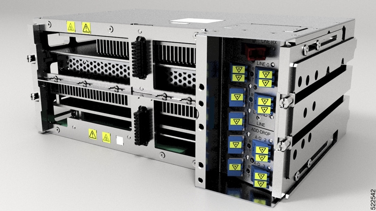
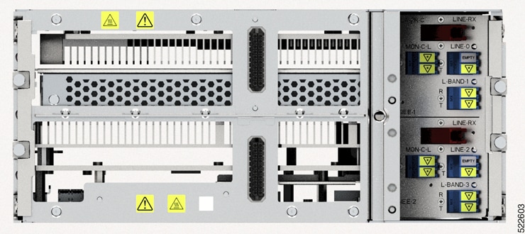
Specifications of Cisco QSFP-DD pluggable OLS
The QSFP-DD Open Line System (OLS) is a pluggable solution that integrates with Cisco routers. This optical amplifier module, when used with channel breakout options, provides a simple and powerful open line system in a pluggable form factor.
Cisco QSFP-DD pluggable OLS
The QSFP-DD OLS is a pluggable module that integrates two variable-gain amplifiers: a pre-amplifier and a booster amplifier. These amplifiers boost both the up and down fiber streams.
Various channel breakout options are available to combine or separate each channel from a coherent DWDM optical source. The TX-EDFA acts as a booster amplifier and compensates for the loss from the optical multiplexers, providing a power boost before the link. The RX-EDFA serves as a preamplifier that restores link loss, increasing the optical signal to a level above the receiver sensitivity after the demultiplexer.
The QSFP-DD OLS extends the reach of a 400G QSFP-DD ZR and ZR+ link from 40 to 130 km or farther, based on fiber specifications, channel count, and line rate. For Bright 400G QSFP-DD ZR and ZR+ links, the extension range is 80 to 130 km or farther, subject to the same factors.
Industry-standard CS connectors enable you to integrate ingress and egress ports on the QSFP-DD OLS faceplate. The QSFP-DD-OLS offers two bi-directional optical ports: COM-RX and TX, which connect to the Mux or DMX unit, and LINE-TX or RX, which connect to the fiber link.
The optical connectors are 2x CS-UPC. The CS connector provides the characteristics and simplicity of the duplex LC connector into a smaller footprint to allow two pairs of CS connectors to fit within the physical constraints of the QSFP-DD form factor. Since the other optical units like Coherent Interfaces modules, DWDM Add and Drop multiplexers, and fiber patch panels have normally LC connectors, a hybrid adaptation patch cord with a CS dual connector on one side and two LC connectors on the other side is available to interconnect the QSFP-DD-OLS modules with other optical equipment.
Optical safety is enabled by default to
-
switch off each section independently in case Optical LOS is detected at its input, and
-
set the TX-EDFA in Automatic Power Reduction (APR) at 8dBm in case a LOS is cleared at the COM-RX port, but LOS is still present at LINE-RX.
This table shows the routers and line cards that support Cisco QSFP-DD pluggable OLS (QSFP-DD OLS) and the release from which they support the module.
|
IOS-XR release |
Platform |
|---|---|
|
7.10.1 |
|
|
24.1.1 |
|
|
24.3.1 |
|
|
24.4.1 |
|
Multi-channel line system using QSFP-DD OLS
The user can build a multi-channel line system using the QSFP-DD OLS and its associated components:
-
A single-channel system: It requires no special components to add and drop. A special CS-LC cable (ONS-CAB-CS-LC-5) has been made available to interconnect LC ports of the QSFP-DD coherent source or the network with the CS ports of the QSFP-DD OLS. One pair of these cables is sufficient to make a single-channel system. All the gain of the amplifier is available for the single channel in focus.
-
A four-channel system: To achieve a 4-channel combine and split, an FLD-4 (fixed 4 channel OADM) can be used. This is a passive optical Add/Drop unit belonging to the ONS-15216 platform that is able to multiplex or demultiplex 4 channels over the 100GHz ITU grid.
-
A eight-channel system: To achieve an 8-channel combine and split, a 1x8 channel breakout cable can be used. This new breakout cable (ONS-BRK-CS-8LC) is a dual fanout 1x8 cable with an embedded passive splitter and coupler. The cable is grid-less, allowing any port to receive any optical frequency without constraints on frequency value or channel spacing.
-
A 16-channel system: To achieve a 16-channel combine and split, a 1x16 channel breakout cable can be used. This new breakout cable (ONS-BRK-CS-16LC) is a dual fanout 1x16 cable with an embedded passive splitter and coupler. The cable is grid-less so any port can be fed with any optical frequency without any constraints of frequency value or spacing between the channels.
-
A 32-channel system: To achieve a 32-channel combine and split, a 64-channel multiplexer or demultiplexer can be used (of which 32 channels are used). The NCS1K-MD-64-C is a passive optical Add/Drop unit for the NCS1K platform, capable of multiplexing or demultiplexing up to 64 channels over the 75GHz grid. Due to the limited operating bandwidth of the QSFP-DD-OLS, only a subset of the MD-64 channels can be used: from port CH-19 (194.75 THz) to port CH-50 (192.425 THz).
For more information on configuring Cisco QSFP-DD pluggable OLS, see Configuring QDD Optical Line System. For more information on the Cisco QSFP-DD pluggable OLS, see the Cisco QSFP-DD Pluggable Open Line System Data Sheet.
Modules in Cisco Network Convergence System 2000 series
The Cisco Network Convergence System 2000 series delivers agility, programmability, and massive scale across ultra-long haul, metro, and enterprise optical networks. Using the Cisco NCS 2000 series, you can deploy a simple, yet intelligent dense wavelength-division multiplexing (DWDM) network that scales with operational ease. The NCS 2000 devices are managed by the Shelf Virtualization Orchestrator (SVO) available in , Release 12.3.1.
Cisco NCS 2006 shelf
The NCS 2006 shelf has eight horizontal card slots. The chassis is six RU, with six slots for service cards and two slots for controller cards. It supports multishelf management of up to 50 shelves.
For more information on Cisco Network Convergence System 2000 series, see the Cisco Network Convergence System 2000 Series Data Sheet.
Shelf Virtualization Orchestrator
Cisco NCS 2000 Shelf Virtualization Orchestrator (SVO) introduces programmability of optical network elements and automation with NETCONF interface and YANG models. SVO enables end-to-end, software-defined automated networks that help maximize customer revenue and simplify network turn-up, operation, and maintenance.
SVO is available with a server on a blade encasing a high-speed processor with virtualized instances of multiple reconfigurable optical add/drop multiplexer (ROADM), optical line amplifier (OLA), and dynamic gain equalizer (DGE) sites of the network.
An SVO line card, together with the application software, provides licenses for alarm correlation, performance monitoring, connection verification, and optical time domain reflectometry (OTDR).
The Cisco NCS 2000 SVO helps to maintain and improve profitability with the orchestration of network elements and their functionalities. SVO allows the network elements to do only forwarding functions. SVO manages the configuration and monitoring of network elements at the node level using a centralized controller.
For more information on Cisco NCS 2000 Shelf Virtualization Orchestrator, see the Cisco NCS 2000 Shelf Virtualization Orchestrator Data Sheet.
Control cards
Cisco NCS 2000 Series Transport Node Controller 2 with Optical Time Domain Reflectometry (TNCS-2O) card performs these key operations:
-
system initialization
-
provisioning
-
alarm reporting
-
maintenance and diagnostics
-
IP addressing
-
Data-Communications-Channel (DCC) termination
-
monitoring of system input voltage
-
system fault detection
-
multishelf management connections
Optical Time Domain Reflectometry (OTDR) provides information about the basic characteristics of the optical fiber among optical nodes, such as insertion loss, concentration points of reflection, fiber-to-fiber connection losses, and reflectance.
For more information on Cisco Transport Node Controller (TNC) and Transport Shelf Controller (TSC) cards, see the Cisco Transport Node Controller and Transport Shelf Controller Cards Data Sheet.
ROADM cards
The 20-SMRFS card is tunable over 96 channels in the C band, at 50-GHz spacing on the ITU-T grid. The card provides flex spectrum capability, allowing flexible allocation of channel bandwidth and improved network scalability. With flex capability, channel bandwidth is adjustable and can be defined arbitrarily, with specified granularity and within a given range. The card increases network flexibility by allowing reconfiguration of optical channels at any time.
The 20-SMRFS card is a single-slot card that integrates two cross-connect blocks (multiplexer and demultiplexer), a variable-gain EDFA preamplifier, and a variable-gain EDFA booster amplifier. The card supports up to 20 directions for each ROADM node. The EDFA preamplifier in this card has gain ranges of 0 to 17 dB and 12 to 24 dB with controlled tilt and extended gain ranges of 20 dB and 35 dB with uncontrolled tilt.
For more information on Cisco NCS 2000 SMRFS line card, see the Cisco NCS 2000 Flex Spectrum Single Module ROADM Line Cards Data Sheet.
Amplifier cards
The Cisco NCS 2000 offers enhanced optical amplifier cards operating in the C band region of the optical spectrum to extend the reach and capacity of a metro, regional, or long-haul network. The optical amplifier cards are part of the Cisco NCS 2000 intelligent DWDM architecture that is engineered to reduce DWDM complexity and speed the deployment of next-generation networking solutions.
EDFA cards
The OPT-EDFA-17 and OPT-EDFA-35 cards are C band DWDM EDFA amplifiers and preamplifiers. The cards are true variable gain amplifiers, offering an optimal equalization of the transmitted optical channels over a wide gain range. They support 96 channels at 50-GHz channel spacing in the C band (that is, 1528.77 to 1566.72 nm wavelength range). The OPT-EDFA-17 card delivers 20 dBm output power. The OPT-EDFA-35 card delivers +23 dBm output power. These cards do not contain midstage access loss for a Dispersion Compensation Unit (DCU). The cards provide a noise-figure optimized version of the EDFA amplifiers to cope with new modulation formats like PM-DQPSK, which do not need dispersion compensation.
For more information on Enhanced C band 96-channel EDFA amplifiers for the Cisco ONS 15454 Multiservice Transport Platform (MSTP), see the Enhanced C-Band 96-Channel EDFA Amplifiers for the Cisco ONS 15454 MSTP Data Sheet.
EDRA cards
The double-slot EDRA-2-26 card combines standard erbium-doped fiber amplifiers and a Raman amplifier to enable amplification on long unregenerated spans. These plug-in modules support an ultra-low noise figure that is critical for long-distance, high-bit-rate transmission. They support 96 channels in the C band (wavelengths from 1528.77 to 1566.72 nm), providing the reach and optical performance required to meet the most demanding distance requirements of service provider and enterprise DWDM networks. EDRA-2-26 includes an erbium-doped preamplifier, EDFA1, with a nominal gain of 14 dB and an erbium-doped booster amplifier, EDFA2. It supports a maximum span of 26 dB on standard single-mode fiber.
For more information on Cisco Network Convergence System 2000 series Erbium Doped Raman amplifiers, see the Cisco Network Convergence System 2000 Series Erbium-Doped Raman Amplifiers Data Sheet.
Raman amplifier cards
The Cisco ONS 15454 MSTP high-power counter-propagating Raman amplifiers operate in the C band region of the optical spectrum to extend the reach and capacity of regional, long-haul, and ultra-long-haul optical.
Raman amplifiers use the intrinsic properties of silica fiber in such a way that the transmission fibers themselves become a medium for amplification. This approach allows the attenuation of data signals transmitted over the fiber to be mitigated within the fiber itself. An amplifier using this principle is commonly known as a distributed Raman amplifier or simply, a Raman amplifier. The high-power counterpropagating unit injects counterpropagating optical power to generate a Raman effect in the span fiber and thus amplifies the signals propagating in the same fiber.
The single-slot RAMAN-CTP card supports counter Raman amplification on long unregenerated spans. The cards manage up to 96 ITU-T 50 GHz spaced channels over the C band of the optical spectrum (wavelengths from 1528.77 to 1566.72 nm).
For more information on high-power counter-propagating and co-propagating Raman units for the Cisco ONS 15454 MSTP, see High Power Counter-Propagating and Co-Propagating Raman units for the Cisco ONS 15454 Multiservice Transport Platform (MSTP).
Passive multiplexer and demultiplexer module
NCS1K-MD-64-C is a passive optical multiplexer and demultiplexer module. The new optical module is based on athermal waveguide (AWG), providing 64 channels at 75 GHz spacing across the extended C band of the optical spectrum. The passive module allows you to transmit 400G ZR and 400G ZR+ wavelengths.
NCS1K-MD-64-C is a bidirectional unit that has the multiplexing and demultiplexing functions implemented as two different sections. The NCS1K-MD-64-C module supports bidirectional connection toward the Router or DCI that is equipped with QDD-400G-ZR-S and QDD-400G-ZRP-S.
For more information on Cisco NCS 1000 multiplexer and demultiplexer 64-channel patch panel module, see Cisco NCS 1000 Mux/Demux 64-Channel Patch Panel Data Sheet
Passive patch panel modules in Cisco Network Convergence System 2000 series
The passive optical modules are used to design the optical network system.
MPO-16 to 16-LC fan-out module
The MPO-16 to 16-LC fan-out module is a double slot module with one MPO-16 connector (COM) and eight LC duplex connectors (Port-i-TX/RX). It contains 16 photodiodes to monitor the power of the channel input ports. The MPO-16 to 16-LC fan-out module provides fan-out of the MPO-16 connector to or from the LC connections and interconnects the optical modules having LC connectors (TXP) with modules having MPO-16 connectors (SMR20 FS).
Cisco 1 x 6 colorless flex spectrum add and drop module
The Cisco 1 x 6 colorless flex spectrum add and drop module (6AD-CFS) is a passive unit including one 1 x 6 splitter and one 6 x 1 combiner, and 7 photodiodes. This module is single-slot height in the mechanical frame chassis. Its primary function is to provide optical multiplexing and demultiplexing for up to six optical signals. Because it is based on optical splitter and combiner technology, only transceivers employing coherent detection can be directly connected to the six client ports of the unit. Integrated photodiodes provide connectivity check and monitoring functions. Virtual PDs are implemented by the unit on the output ports (AD-i-TX, COM-TX) by subtracting the insertion losses from the real photodiode (PD) reading. Power values and the manufacturing data stored in the flash memory are provided to a Cisco Transport Controller (CTC) through the USB connection.
Cisco five-degree modular patch panel module
The Cisco five-degree patch panel module (MF-DEG-5) provides interconnections between five 8-port MPO connectors; it is used to connect any combination of up to five ROADM line degrees (express connections) and add or drop components (add or drop connections). The 40 optical paths are interconnected. Five photodiodes provide power monitoring of fiber 1 of each MPO connector. Power values and the manufacturing data stored in the flash memory are provided to CTC through the USB connection. This module is single-slot height in the mechanical frame chassis.
Cisco four-degree upgrade modular patch panel module
The Cisco four-degree upgrade modular patch panel module (MF-UPG-4) provides interconnections among eight 8-fiber MPO connectors; it is used to expand the number of degrees and the number of add or drop ports that are supported by the node. The 64 optical paths are interconnected. A total of eight photodiodes provides power monitoring of fiber 1 of each MPO connector. Power values, and the manufacturing data stored in the flash memory are provided to a CTC through the USB connection. This module is single-slot height in the mechanical frame chassis.
For more information on Cisco Network Convergence System 2000 series passive patch panel modules, see the Cisco Network Convergence System 2000 Series Passive Patch Panel Modules Data Sheet.
Modules in Cisco Network Convergence System 1010
Cisco NCS 1010 is a next-generation optical line system optimized for ZR and ZR+ WDM interfaces in routers. The system provides point-to-point connectivity between routers with WDM interfaces and multiplexes WDM signals from multiple routers over a single fiber. In addition, the system supports ROADM express of up to eight degrees. It supports both C band transmission and C+L combined WDM transmission, maximizing capacity.
Modules in Cisco NCS 1010
Cisco NCS 1010 is a three RU chassis that has an in-built External Interface Timing Unit (EITU) and these field-replaceable modules:
-
Controller
-
Two power supply units
-
Two fan trays
-
Fan filter
-
Line card
Line cards in Cisco NCS 1010
There are five different variants of the line card:
-
OLT-C line card: C band Optical Line Terminal (OLT) without Raman
-
OLT-R-C line card: C band OLT with Raman
-
ILA-C line card: C band In-Line Amplifier (ILA) without Raman
-
ILA-R-C line card: C band ILA with one side Raman
-
ILA-2R-C line card: C band ILA with both sides Raman
NCS 1010 for Routed Optical Networking
These features of the NCS 1010 Optical Line Systems (OLS) make it ideal for Routed Optical Networking:
-
Support for low-power coherent sources
-
Ingress EDFA amplifier on OLTs to support 400ZR and OpenZR+ DCOs.
-
Low loss couplers to support 95 and 140 GBaud rates that need higher Rx power.
-
-
Capacity scaling built-in by design
-
Hitless upgrade from C band to C+L band
-
Embedded channelized ASE for consistency in performance from day-1 to full capacity growth
-
33-port Twin-WSS architecture to use as express or add and drop
-
-
Simplicity of the OLS
-
Simpler integrated module
-
Independent degree operation
-
Automated turn-up
-
Full spectrum loading from the beginning
-
DGE on ILAs for equalization and better control of Raman Gain ripple
-
-
Automation of entire life cycle
-
Device automation using ZTP, OpenConfig YANG configuration and telemetry
-
Automated E2E turn-up with embedded control loops
-
Automated connection verification for patch loss checks at each site
-
Enhanced visibility using OTDR, OSC, and OCM
-
Cisco NCS 1000 32-channel multiplexer and demultiplexer patch panel
The Cisco NCS 1000 32-channel multiplexer and demultiplexer patch panels are a pair of passive Athermal Arrayed Waveguide Grating (AAWG) base modules (PIDs NCS1K-MD-32O-C and NCS1K-MD32E-C). Each multiplexer and demultiplexer panel has 32 channels. It serves as an add and drop unit for the OLT-C and OLT-R-C line cards. Each multiplexer and demultiplexer panel allows the multiplexing and demultiplexing of 32 channels with 150-GHz spacing. 75 GHz frequency shift exists between the ODD and EVEN panels. When both the panels are used on the same OLT (OLT-C and OLT-R-C) line cards, their combined capacity is 64 channels with 75 GHz spacing. Each multiplexer and demultiplexer panel provides wide optical pass-band support. When used standalone, each panel acts as an add and drop unit for 32 channels operating at 140 gigabaud.
The NCS1K-MD32O/E-C panel operates in C band. The Cisco NCS 1000 multiplexer and demultiplexer patch panels are fully passive. The units are powered by a USB 3.0 connection in the NCS 1010 chassis. The panels monitor signals, verify connections, and retrieve the inventory data.
Cisco NCS 1000 breakout patch panel and modules
Cisco NCS 1000 breakout patch panel
Cisco NCS 1000 breakout patch panel is a colorless breakout-modular patch panel. It is powered by the NCS 1010 chassis using a single USB 3.0 cable. The breakout panel contains four USB 2.0 connections that power the passive optical modules. It allows connections between the OLT-C and OLT-R-C line cards installed in the NCS 1010 chassis and the optical passive modules using MPO cables. The breakout panel is four RU high and has adjustable fiber guides for fiber routing. The empty slots are covered with dummy covers.
The NCS1K-BRK-SA breakout panel is a four RU breakout patch panel. It interfaces four passive optical modules with the NCS 1010 chassis. The breakout panel supports up to 72 colorless multiplexer and demultiplexer channels. The breakout panel supports 8-directional interconnections.
The panel is shipped with USB 2.0 connectors connected to the corresponding dummy covers. The plastic transparent cover can be installed in front of the panel for fiber protection. The panel is designed to fit a 19-inch rack. The panel can also be installed on ETSI and 23-inch rack using adapter brackets.
Cisco NCS 1000 breakout modules
The Cisco NCS 1000 breakout Modules are a set of three optical breakout units. The modules can be connected to the A/D 4 to 11, A/D 12 to 19, A/D 20 to 27 and A/D 28 to 33 MPO connector ports of the OLT-C and OLT-R-C line cards to provide ROADM node internal connections and for local channels add and drop.
The breakout panel supports these passive optical modules:
NCS1K-BRK-8
The NCS1K-BRK-8 module provides the breakout of 16 fibers from an MPO-24 connector to eight duplex line card connectors. It essentially performs an optical connection adaptation of MPO-to-LC connectors for the ADD and mDROPi signals of the MPO ports on OLT line cards. For each port—MPO and LC—, power monitors with tone detection capability are available. A filtered optical loopback (191.175 THz) from one MPO input port (fiber-1) to all MPO output ports is available for connection verification.
NCS1K-BRK-24
The NCS1K-BRK-24 module provides the breakout of 16 fibers from an MPO-24 connector to 24 duplex LC connectors. The signals on each fiber from the MPO input ports are split over three LC output ports by a 1x3 optical splitter. The signals from the three adjacent input LC ports are combined into a single MPO fiber output port through a 1x3 optical coupler. For each port (MPO and LC), power monitors with tone detection capability are available. A filtered optical loopback (191.175 THz) from one MPO input port (fiber-1) to all MPO output ports is available for connection verification.
For more information about the Cisco Network Convergence System 1010, see the Cisco Network Convergence System 1010 Data Sheet .
 Feedback