Automation Workflows

This chapter describes the installation and communication sequence of the Routed Optical Networking components. The chapter also includes some Routed Optical Networking ML service provisioning examples.

Install Routed Optical Networking components

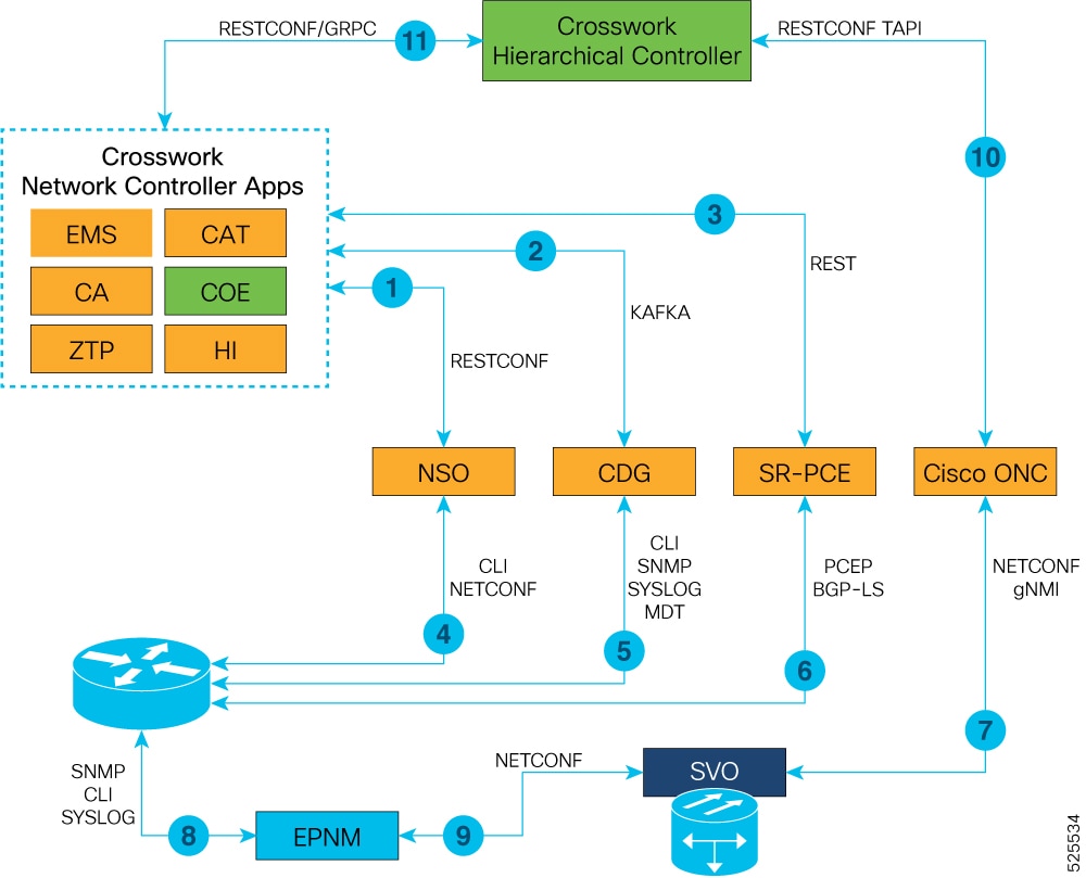
Cisco Crosswork Hierarchical Controller, Crosswork Network Controller Essentials, and NSO 6.1.9 with Routed Optical Networking 3.0.0 Function Pack are the necessary components for the Routed Optical Networking solution. Cisco Optical Network Controller is required when using Cisco optical networking components.

Follow these steps to install the components of the Routed Optical Networking solution.

Procedure


Install the Routed Optical Networking components in this sequence.

Table 1. Installation sequence of Routed Optical Networking components

Task

See

Install Cisco Optical Network Planner.

Cisco Optical Network Planner determines the optical layer feasibility and identifies the components needed to support the network. It also generates a BoM for the planned hardware deployment.

Cisco Optical Network Planner Installation Guide

Install SVO to manage the NCS 2000 optical components and create SVO instances to manage NCS 2000 devices.

Cisco NCS 2000 Series SVO Configuration Guide, Release 12.3.x

Install the Crosswork Infrastructure , Crosswork Data Gateway, and supporting Crosswork Network Controller 7.1applications such as Crosswork Optimization Engine, CAT, and Hi.

Cisco Crosswork Network Controller 7.1 Installation Guide

Install Cisco Optical Network Controller 25.1.2

Cisco Optical Network Controller 25.1.x Installation Guide

Install EPNM 7.1.2 EMS to manage the physical router and the optical network nodes.

Installation Guide for Cisco Evolved Programmable Network Manager 8.1

Install Cisco NSO 6.1.96.4.1.1, Routed Optical Networking Multi-layer Function Pack 3.0, and Crosswork DLM function pack. Optionally, install the Cisco Transport SDN Function pack for SR-TE and xVPN service management.

Cisco Network Services Orchestrator Getting Started Guide, Cisco NSO Routed Optical Networking Core Function Pack Installation Guide, Cisco NSO Transport SDN Function Pack Installation Guide 6.0.0, Cisco NSO DLM Service Pack Installation Guide 6.0.0

Add NCS 1010 devices to Cisco Optical Network Controller for the optical service management.

Cisco Optical Network Controller 25.1.x Configuration Guide

Install Crosswork Hierarchical Controller 11.0

Crosswork Hierarchical Controller 11.0

Install Segment Routing - Path Computation Element (SR-PCE) in the network for Segment Routing - Traffic Engineering (SR-TE) or Resource Reservation Protocol - Traffic Engineering (RSVP-TE) discovery and visualization and add NSO, SR-PCE, and Cisco routers to the Crosswork cluster.

Add Cisco NSO Providers, Add Cisco SR-PCE Providers, Adding Devices to Inventory

Add the Cisco Optical Network Controller instance as a device in NSO to support end-to-end multi-layer provisioning.

Cisco NSO Routed Optical Networking Core Function Pack User Guide


You have installed all the components of the Routed Optical Networking solution.

How Routed Optical Networkingcomponents communicate

Summary

The components of Routed Optical Networking perform several operations such as service discovery, node management, and collection of inventory data to communicate together.

Workflow

This diagram displays the communication sequence between the Routed Optical Networking components.

Figure 1. Routed Optical Networking communication flow
Routed Optical Networking communication flow

These stages describe how the Routed Optical Networking components communicate in Release 4.0

  1. Crosswork Network Controller discovers services. Crosswork Network Controller populates NSO with device information using RESTCONF and handles NSO provisioning requests. EMS collects fault and alarm data from devices.

  2. Crosswork Data Gateway sends device status and data to Crosswork Network Controller. Crosswork Network Controller manages the Crosswork Data Gateway instance.

  3. SR-PCE sends SR-TE/RSVP-TE and topology information to Crosswork Network Controller using REST APIs.

  4. NSO manages IOS XR router configuration using NETCONF and CLI.

  5. Crosswork Data Gateway collects network information from XR routers using CLI, SNMP, and MDT.

  6. SR-PCE acts as a network PCE and collects IGP topology information from the network using PCEP and BGP-LS.

  7. Cisco Optical Network Controller manages the SVO and NCS 1010 network nodes using NETCONF and gNMI. Cisco Optical Network Controller communicates with Cisco Optical Site Manager for NCS 1010

  8. EPNM performs router inventory, SWIM, fault, and performance data collection using SNMP, CLI, and SYSLOG.

  9. EPNM performs optical inventory, SWIM, fault, and performance data collection for NCS 2000 and NCS 1010 using NETCONF.

  10. Crosswork Hierarchical Controller discovers optical equipment, topology, and services and provisions optical services using TAPI. Crosswork Hierarchical Controller receives PM data using ONC RPC.

  11. Crosswork Hierarchical Controller discovers IGP nodes and topology and provisions services using Crosswork Network Controller NB API. Crosswork Hierarchical Controller receives PM data from Crosswork Network Controller using GRPC. Crosswork Hierarchical Controller discovers router, DCO, and QDD-OLS inventory from Crosswork Network Controller.


Note


Routed Optical Networking components are not required in all the deployments.


Provision end-to-end service for Cisco routers with only ZR or ZR+ optics

These diagrams illustrate a network containing Cisco routers equipped with ZR or ZR+ optics and a non-Cisco optical line system.

Figure 2. Cisco routers with ZR or ZR+ optics
Cisco routers with ZR or ZR+ optics

Follow this step to provision end-to-end service using Cisco routers with only ZR or ZR+ optics.

Procedure


Create Routed Optical Networking ML service with these parameters.

Table 2. Parameters for Routed Optical Networking ML Service

Input

Value

End-points

ron-8201-1, ron-8201-2

Model

Transponder (1x400G mode)

Bandwidth

400G

Frequency

1952000

TX Power

-12 dB on both endpoints

IP Addressing

10.2.1.10/31 and 10.2.1.11/31 on FourHundredGigE 0/0/0/8

ron ron-ml ron-8201-1_ron-8201-2
 mode      transponder
 bandwidth 400
 circuit-id "Router Only"
 frequency  1952000
 end-point ron-8201-1
  terminal-device-optical line-port 0/0/0/8
  terminal-device-optical transmit-power -120
  terminal-device-packet interface 0
   ip-address v4 10.2.1.10/31
  !
 !
 end-point ron-8201-2
  terminal-device-optical line-port 0/0/0/8
  terminal-device-optical transmit-power -120
  terminal-device-packet interface 0
   ip-address v4 10.2.1.11/31
  !
 !
!

How NSO Routed Optical Networking ML service works

Summary

The Routed Optical Networking ML service performs several operations to provision an end-to-end service using Cisco routers with ZR or ZR+ optics.

Workflow

This diagram displays the NSO Routed Optical Networking ML service workflow for an end-to-end service using Cisco routers with ZR or ZR+ optics.

Figure 3. NSO Routed Optical Networking ML service sequence
NSO Routed Optical Networking ML service sequence

These stages describe the workflow of the Routed Optical Networking ML service.

  1. The user initiates the Routed Optical Networking ML provisioning request.

  2. The Routed Optical Networking ML service retrieves the transceiver and line card PIDs for each router endpoint using Routed Optical Networking CLI NED.

  3. The Routed Optical Networking ML service compares the received transceiver PIDs and determines whether the transceivers can support the service.

  4. The Routed Optical Networking ML service compares the received line card PIDs and determines whether the line cards require configuration.

  5. The Routed Optical Networking ML service provisions the router optics ports. It optionally performs bundle and IP configuration using the Cisco YANG models.

  6. The Routed Optical Networking ML service stores the service information as NSO operational data and also returns the service state to the user.

How Crosswork Hierarchical Controller provisions Routed Optical Networking circuit

Summary

Crosswork Hierarchical Controller provisions the Routed Optical Networking circuit through several operations.

Workflow

The stages in the diagram describe the workflow for provisioning the Routed Optical Networking circuit in the Crosswork Hierarchical Controller GUI through the Crosswork Network Controller.

Figure 4. Crosswork Hierarchical Controller provisioning workflow
Crosswork Hierarchical Controller Provisioning Workflow

Note


The workflow does not support provisioning a complete end-to-end service in a network that contains Cisco routers with ZR or ZR+ optics and a non-Cisco optical line system.


Automation starter solution

Automation starter solution

The automation starter solution is a simplified automation stack to manage ZR/ZR+ optics in Cisco routers. This solution accelerates the adoption of Routed Optical Networking by simplifying the installation and deployment processes.

The primary difference between the starter and full solutions is that the starter solution lacks CNC. In the starter solution, the Crosswork Hierarchical Controller communicates with Cisco routers using the IOS XR (only in R3.0) and NSO adapters, and communicates with optical networks using the appropriate optical controller adapter.

Both the starter and full solutions use the same NSO RON-ML function pack. The function pack version is 3.0

From Release 4.0, IOS XR adapter is not supported in the starter solution. Crosswork Network Controller EMS provides minimal installation to support full IP network inventory, basic topology, and PM data delivered through its integrated Crosswork Data Gateway.

From Release 4.0, IOS XR adapter is not supported in the full solution. Crosswork Network Controller provides the necessary inventory and state information to Crosswork Hierarchical Controller through NB API.

Automation starter solution versus full solution

This diagram displays the components that are involved in the automation starter solution and full solution.

Figure 5. Automation starter solution versus full solution in release 4.0
Automation starter solution versus full solution in release 4.0

Features and adapters in automation starter solution and full solution

This table lists the features supported in both the automation starter solution and the full solution.

Table 3. Features in automation starter solution and full solution

Feature

Automation starter solution

Full solution

Wavelength provisioning

Yes

Yes

Optical circuit assurance and troubleshooting

Yes

Yes

Multilayer visualization and History view

Yes

Yes

Management and verification of optical to IP connections

Yes

Yes

SR and SRv6 control plane SDN automation

No

Yes

IP element management and IP SDN path optimization

No

Yes

IP service assurance and service orchestration

No

Yes

PLE automation including SR-CS bandwidth reservation, provisioning, and assurance

No

Yes

This table lists the adapters required for both the automation starter solution and the full solution.

Table 4. Required adapters in automation starter solution and full solution

Type of solution

Required adapters

Use

Full solution

  • CNC adapter

  • (Only in R3.0) IOS-XR adapter

  • NSO adapter and RON-ML function pack

  • Optical adapters

  • CONC adapter

  • Inventory, physical and IGP topology, segment routing, and service discovery

  • PM collection

  • RON inventory and topology

  • RON link provisioning

  • Optical Line System

  • Cisco Optical Network Controller

Starter solution

  • (Only in R3.0) IOS-XR adapter

  • NSO adapter and RON-ML function pack

  • Optical adapters

  • CONC adapter

  • RON inventory and topology

  • RON link provisioning

  • Optical Line System

  • Cisco Optical Network Controller

How communication works in automation starter solution

Summary

The components of Routed Optical Networking perform operations to communicate in the automation starter solution.

Workflow

This diagram displays the communication workflow between the Routed Optical Networking components in the automation starter solution.

Figure 6. Communication workflow in automation starter solution in release 4.0
Communication workflow in automation starter solution in release 4.0

These stages describe how Routed Optical Networking components communicate in the automation starter solution in Release 4.0.

  1. Crosswork Hierarchical Controller communicates with the Crosswork Network Controller to collect hardware inventory, optics inventory and state, topology and PM data using integrated Crosswork Data Gateway.

  2. Crosswork Network Controller makes provisioning requests but can use the internal NSO that is part of Crosswork Hierarchical Controller to provision end devices.

  3. NSO communicates with the router for router configuration management, DCO, and IP link provisioning.

  4. Crosswork Hierarchical Controller discovers optical equipment, topology, services, and provisions optical services using TAPI and PM data using CONC RPC.

  5. CONC communicates with SVO and Cisco Optical Site Manager for end-to-end optical device management.

Troubleshoot Provisioning Issues

Provisioning on ZR or ZR+ Optics

  • To check the controller state on the router, use:

    RP/0/RP0/CPU0:ron-8201-1#show controllers optics 0/0/0/20
    Thu Jun  3 15:34:44.098 PDT
    
     Controller State: Up
    
     Transport Admin State: In Service
    
     Laser State: On
    
     LED State: Green
    
     FEC State: FEC ENABLED
    
     Optics Status
    
             Optics Type:  QSFPDD 400G ZR
             DWDM carrier Info: C BAND, MSA ITU Channel=10, Frequency=195.65THz,
             Wavelength=1532.290nm
    
             Alarm Status:
             -------------
             Detected Alarms: None
    
    
             LOS/LOL/Fault Status:
    
             Alarm Statistics:
    
             -------------
             HIGH-RX-PWR = 0            LOW-RX-PWR = 0
             HIGH-TX-PWR = 0            LOW-TX-PWR = 4
             HIGH-LBC = 0               HIGH-DGD = 1
             OOR-CD = 0                 OSNR = 10
             WVL-OOL = 0                MEA  = 0
             IMPROPER-REM = 0
             TX-POWER-PROV-MISMATCH = 0
             Laser Bias Current = 0.0 %
             Actual TX Power = -7.17 dBm
             RX Power = -9.83 dBm
             RX Signal Power = -9.18 dBm
             Frequency Offset = 9 MHz
    
    RP/0/RP0/CPU0:ron-8201-1#show controllers coherentDSP 0/0/0/20
    Thu Jun  3 15:38:04.565 PDT
    
    Port                                            : CoherentDSP 0/0/0/20
    Controller State                                : Up
    Inherited Secondary State                       : Normal
    Configured Secondary State                      : Normal
    Derived State                                   : In Service
    Loopback mode                                   : None
    BER Thresholds                                  : SF = 1.0E-5  SD = 1.0E-7
    Performance Monitoring                          : Enable
    Bandwidth                                       : 400.0Gb/s
    
    Alarm Information:
    LOS = 8 LOF = 0 LOM = 0
    OOF = 0 OOM = 0 AIS = 0
    IAE = 0 BIAE = 0        SF_BER = 0
    SD_BER = 0      BDI = 0 TIM = 0
    FECMISMATCH = 0 FEC-UNC = 0     FLEXO_GIDM = 0
    FLEXO-MM = 0    FLEXO-LOM = 0   FLEXO-RDI = 0
    FLEXO-LOF = 2
    Detected Alarms                                 : None
    
    Bit Error Rate Information
    PREFEC  BER                                     : 1.5E-03
    POSTFEC BER                                     : 0.0E+00
    Q-Factor                                        : 9.40 dB
    
    Q-Margin                                        : 2.20dB
    
    OTU TTI Received
    
    FEC mode                                        : C_FEC
    
  • To gather the performance measurement data, use:

    RP/0/RP0/CPU0:ron-8201-1#show controllers optics 0/0/0/20 pm current 30-sec optics 1
    Thu Jun  3 15:39:40.428 PDT
    
    Optics in the current interval [15:39:30 - 15:39:40 Thu Jun 3 2021]
    
    Optics current bucket type : Valid
                   MIN       AVG       MAX    Operational Configured TCA   Operational Configured TCA
                                              Th(min)     Th(min)   (min)  Th(max)     Th(max)   (max)
    LBC[% ]      : 0.0       0.0       0.0      0.0          NA       NO   100.0       NA          NO
    OPT[dBm]     : -7.17     -7.17     -7.17    -15.09       NA       NO   0.00        NA          NO
    OPR[dBm]     : -9.86     -9.86     -9.85    -30.00       NA       NO   8.00        NA          NO
    CD[ps/nm]    : -489      -488      -488     -80000       NA       NO   80000       NA          NO
    DGD[ps ]     : 1.00      1.50      2.00     0.00         NA       NO   80.00       NA          NO
    SOPMD[ps^2]  : 28.00     38.80     49.00    0.00         NA       NO   2000.00     NA          NO
    OSNR[dB]     : 34.90     35.12     35.40    0.00         NA       NO   40.00       NA          NO
    PDL[dB]      : 0.70      0.71      0.80     0.00         NA       NO   7.00        NA          NO
    PCR[rad/s]   : 0.00      0.00      0.00     0.00         NA       NO   2500000.00  NA          NO
    RX_SIG[dBm]  : -9.23     -9.22     -9.21    -30.00       NA       NO   1.00        NA          NO
    FREQ_OFF[Mhz]: -2        -1        4        -3600        NA       NO   3600        NA          NO
    SNR[dB]      : 16.80     16.99     17.20    7.00         NA       NO   100.00      NA          NO
    RP/0/RP0/CPU0:ron-8201-1#show controllers coherentDSP 0/0/0/20 pm current 30-sec fec
    Thu Jun  3 15:42:28.510 PDT
    
    g709 FEC in the current interval [15:42:00 - 15:42:28 Thu Jun 3 2021]
    
    FEC current bucket type : Valid
        EC-BITS   : 20221314973             Threshold : 83203400000            TCA(enable)  : YES
        UC-WORDS  : 0                       Threshold : 5                      TCA(enable)  : YES
    
                  MIN       AVG        MAX      Threshold      TCA     Threshold     TCA
                                                  (min)     (enable)    (max)     (enable)
    PreFEC BER  : 1.5E-03   1.5E-03   1.6E-03      0E-15        NO       0E-15        NO
    PostFEC BER :  E-15     0E-15     0E-15      0E-15        NO       0E-15        NO
    Q[dB]       : 9.40      9.40      9.40          0.00        NO        0.00        NO
    Q_Margin[dB]: 2.20      2.20      2.20          0.00        NO        0.00        NO
    
    Last clearing of "show controllers OTU" counters never

This table contains the streaming telemetry sensor paths and the information fields that you receive from them.

Sensor path Information Fields

Cisco-IOS-XR-controller-optics-oper:optics-

oper/optics-ports/optics-port/optics-info

alarm-detected, baud-rate, dwdm-carrier-frequency, controller-state, laser-state, optical-signal-to-noise-ratio, temperature, voltage

Cisco-IOS-XR-controller-optics-oper:optics-

oper/optics-ports/optics-port/optics-lanes/optics-lane

receive-power, receive-signal-power, transmit-power

Cisco-IOS-XR-controller-otu-

oper:otu/controllers/controller/info

bandwidth, ec-value, post-fec-ber, pre-fec-ber, qfactor, qmargin, uc

Cisco-IOS-XR-pmengine-oper:performance-

management/optics/optics-ports/optics-port/optics-

current/optics-second30/optics-second30-optics/optics-

second30-optic

dd__average, dgd__average, opr__average, opt__average, osnr__average, pcr__average, pmd__average, rx-sig-pow__average, snr__average, sopmd__average

Cisco-IOS-XR-pmengine-oper:performance-

management/otu/otu-ports/otu-port/otu-current/otu-

second30/otu-second30fecs/otu-second30fec

ec-bits__data, post-fec-ber__average, pre-fec-ber__average, q__average, qmargin__average, uc-words__data


Note


The performance management sensor paths show the sensor path for a 30-second performance measurement (PM) interval. They also support 15 minutes and 24 hours. To access these options, replace second30 in the sensor path with minute15 and hour24 respectively.


Crosswork Hierarchical Controller Provisioning

In the event of a failed configuration, the configuration state transitions to FAILED. The Last Operation is in the Rollback stage where it rolls back the configuration.

Figure 7. Crosswork Hierarchical Controller UI - Operations Tab
Crosswork Hierarchical Controller UI - Operations Tab

After clicking the service, you can click on ERRORS to check the reason for failure. In this case, the discovery of the operational state exceeded the discovery timeout. The reason for this is, one end of the link was in a loopback state, which did not prohibit the provisioning of the ports, but affected the reachability between the two endpoints.

Figure 8. Crosswork Hierarchical Controller UI - Operations Tab
Crosswork Hierarchical Controller UI - Operations Tab

The logs display both the provisioning flow and the rollback flow.

Figure 9. Crosswork Hierarchical Controller UI - Operations Tab
Crosswork Hierarchical Controller UI - Operations Tab