Introduction to Traditional Networks

This chapter provides insight into the business challenge, components of a network, and the current challenges faced by IP and optical networks.

Routed Optical Networking solution

Business challenge

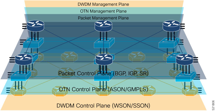
Today's optical and packet networks consist of multiple layers that are stitched together from various domains and vendors. Provisioning services in such complex environments requires tight coordination among different management systems and organizations. It is challenging to operate these networks and the service providers face rising total cost of ownership (TCO). Service providers must simplify and reimagine the architecture to reduce rising operational costs and accelerate the delivery of new services.

Routed Optical Networking solution

The Routed Optical Networking solution aims to simplify networks by removing the complexities inherent to the infrastructure. This solution improves operational efficiency, reduces network TCO, and increases service agility.

The Routed Optical Networking solution allows service providers to leverage their assets more effectively by

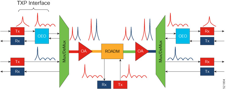
  • creating a simplified converged IP and Optical network

  • using high-speed coherent pluggable modules that provide optimal reach and performance at appropriate cost points and power profiles, and

  • simplifying the network and service lifecycle management by using automation in all phases.

Traditional multilayer network architectures

Traditional network infrastructure consists of an Internet Protocol (IP) layer and an optical transport layer. The optical layer includes a Dense Wavelength Division Multiplexing (DWDM) layer, and optionally, an Optical Transport Network (OTN) switching layer. Each layer possesses its own independent control and management planes.

Types of control planes

  • Distributed control plane: communicates network information between network elements to enable end-to-end communication between network clients.

  • IP control plane: distributes routing information.

  • Optical control plane: performs resource and connection management between optical endpoints.

Network layers and control planes

This table lists the network layers and their corresponding control planes.

Table 1. Network layers and control planes
Network layers Control planes
Packet layer or IP layer BGP, IGP, and segment routing
OTN layer Automatically Switched Optical Network (ASON) and Generalized Multiprotocol Label Switching (GMPLS)
DWDM layer Wavelength Switched Optical Network (WSON) and Shared Services and Outsourcing Network (SSON)
Figure 1. Traditional network architecture
Traditional network architecture

Each layer operates independently with separate redundancy and life cycles. Separate teams are needed to establish and maintain each layer.

Network building blocks

Traditional hierarchical networks consist of an IP layer and an optical transport layer.

IP layer

The IP layer creates and maintains the routing table and forwards packets accordingly. The IP layer of traditional networks consists of interconnected routers.

Routers

Routers are the building blocks of packet networks. They efficiently forward IP or MPLS packets. Routers create any-to-any fabrics to carry most networking traffic, including global Internet traffic. Routers are also responsible for providing different functions based on their role in the network.

Two examples of routers are Core and Provider Edge routers. Core routers use a simplified set of implemented features and supply high capacity interconnect between different regions in a network. Provider Edge (PE) routers support high scale overlay VPN services.

Optical layer

This diagram shows a typical DWDM network.

Figure 2. Typical DWDM network
Typical DWDM Network

This table lists the abbreviations in this image and their expansions.

Table 2. Abbreviations and expansions

TXP

Transponder

OEO

Optical-electrical-optical

Mux

Multiplexer

DeMux

Demultiplexer

OA

Optical amplifier

ROADM

Reconfigurable optical add/drop multiplexer

Building blocks of a typical DWDM network

These are the key building blocks of a typical DWDM network.

  • Optical Transmitters and Receivers: Transmitters provide source signals. They convert digital electrical signals into a light stream of a specific wavelength. Optical receivers detect pulses of light on optical fibers and convert the optical signals into electrical signals.

  • Transponders: Transponders take signals on gray wavelengths and send them in colored wavelengths. Colored wavelengths are wavelengths in the WDM standard. Gray wavelengths are wavelengths not in the WDM standard. A bidirectional transponder also receives a WDM standard bit-stream and converts the signals back to the wavelength used by the client device.

  • Muxponders: Muxponders are similar to transponders. Muxponders take multiple gray wavelength signals and send them in a single colored-wavelength using Time Division Multiplexing (TDM).

  • Multiplexers and Demultiplexers: Multiplexers combine multiple wavelengths from separate fibers into a single composite signal within one fiber. The output of a multiplexer is a composite signal. Demultiplexers take composite signals that compatible multiplexers generate and separate the individual wavelengths into individual fibers.

  • Optical Amplifiers: Optical amplifiers amplify an optical signal. Optical amplifiers increase the total power of the optical signal, enabling its transmission across longer distances. Without amplifiers, the signal attenuation over such distances makes it impossible to coherently receive signals. We use different types of optical amplifiers in optical networks, such as preamplifiers, booster amplifiers, inline amplifiers, and optical line amplifiers.

  • Optical Add and Drop Multiplexers (OADMs): OADMs are devices capable of adding one or more DWDM channels into or dropping them from a fiber.

  • Reconfigurable Optical Add and Drop Multiplexers (ROADMs): ROADMs are programmable versions of OADMs. With ROADMs, you can change the wavelengths that are added or dropped. ROADMs make optical networks flexible and easily modifiable.

Challenges with current IP and optical networks

Current hierarchical service provider networks have up to three different layers, IP, OTN, and DWDM, each with separate control planes. These networks have a layered and siloed architecture relying on dedicated hardware to exchange traffic between layers. The siloed architecture creates separate opaque redundancy mechanisms at each layer, increasing complexity and reducing network efficiency. The large number of devices used to interconnect the layers increase power utilization and the carbon footprint of the network.

The layered and siloed architecture warrants manual service-stitching across network domains. Manual intervention hinders end-to-end automation and increases resolution time, reducing efficiency

Traffic passes through too many elements. The need for separate management of these elements by different departments and the lack of automated management increases the complexity and cost of the network.

Challenges with current service provider networks

Current service provider networks face immense complexities and challenges in

  • network planning

  • provisioning

  • path and network optimization

  • network monitoring, and

  • fault correction.

These complexities and overlapping redundancies create bottlenecks that hinder the efficient scaling of service provider networks.