Components and connections in metro and regional topology
Topology diagram
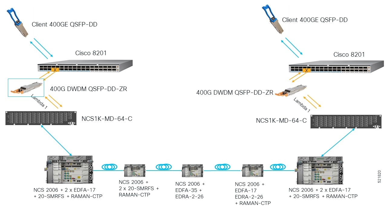
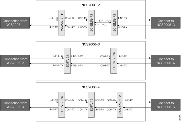
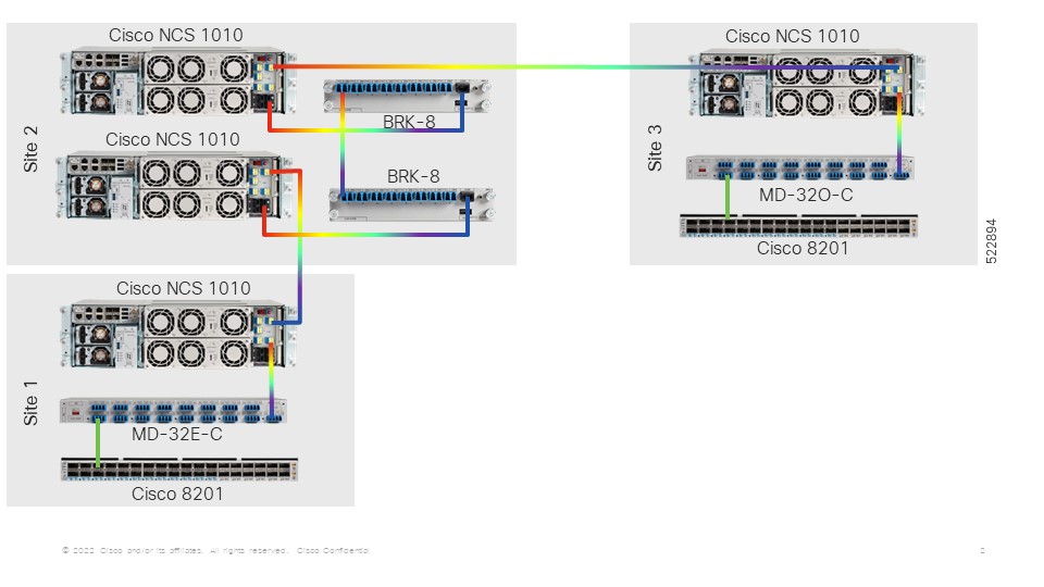
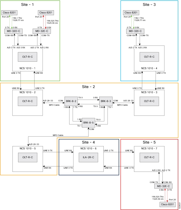
This topology diagram illustrates the setup for metro and regional networks.
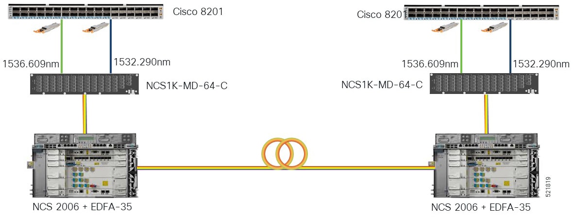
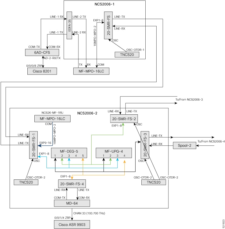
This diagram displays the wiring diagram for the metro and regional topology.
In this sample topology, Cisco 8201-1 serves as the source router and Cisco 8201-2 serves as the destination router.
Topology components
You need this hardware to build this topology:
-
Cisco 8200 series routers
-
NCS1K-MD-64-C modules
-
Cisco NCS 2006 shelves
-
TNCS-2O cards
-
OPT-EDFA-35 cards
-
QDD-400G-ZR-S transceiver module
-
LC/LC cables
For more information, see Hardware components.
Port connections
Use this sequence to connect the cables and build this topology:
-
On the Cisco 8201-1 and Cisco 8201-2 routers:
-
Align the QDD-400G-ZR-S transceiver module in front of the transceiver socket opening in Port 20. Then, carefully slide the transceiver into the socket until the transceiver comes in contact with the socket electrical connector.
-
Holding the pull-tab, fully seat the transceiver in the module’s transceiver socket until it clicks.
-
Attach an LC/LC fiber immediately to the QDD-400G-ZR-S transceiver module.
-
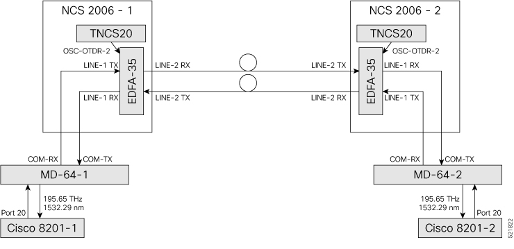
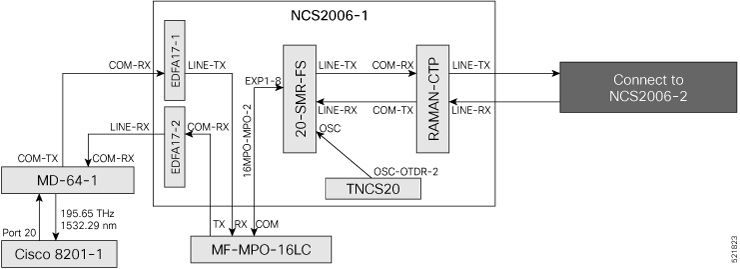
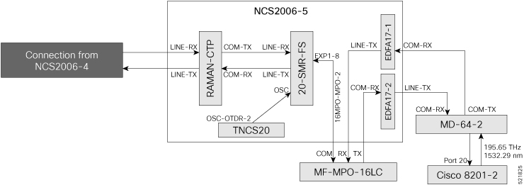
Connect the other end of the LC/LC fiber to the corresponding bulkhead adapter on the front panel of the NCS1K-MD-64-C (MD-64-1) module. In this sample topology, we use channel ID 7, which corresponds to a frequency of 195.65 THz (a wavelength of 1532.29 nm).
-
-
Connect an LC/LC fiber from the COM-RX port of the MD-64-1 module to the LINE-1-TX port of the EDFA 35 amplifier card in NCS 2006-1.
-
Connect an LC/LC fiber from the COM-TX port of the MD-64-1 module to the LINE-1-RX port of the EDFA 35 amplifier card in NCS 2006-1.
-
Connect an LC/LC fiber from the OSC-OTDR-2 port on the TNCS-2O card to the OSC port on the EDFA 35 card in NCS 2001-1.
-
Connect an LC/LC fiber from the LINE-2-RX port of the EDFA-35 card in NCS 2006 -1 to the outside plant fiber that is connected to the LINE-2-TX port of the EDFA-35 card in NCS 2006 -2.
-
Connect an LC/LC fiber from the LINE-2-TX port of the EDFA-35 card in NCS 2006 -1 to the outside plant fiber that is connected to the LINE-2-RX port of the EDFA-35 card in NCS 2006 -2.
-
Connect an LC/LC fiber from the OSC-OTDR-2 port on the TNCS-2O card to the OSC port on the EDFA 35 card in NCS 2006-2.
-
Connect an LC/LC fiber from the LINE-1-RX port of the EDFA-35 card in NCS 2006 -2 to the COM-TX port of the MD-64-2 module.
-
Connect an LC/LC fiber from the LINE-1-TX port of the EDFA-35 card in NCS 2006 -2 to the COM-RX port of the MD-64-2 module.
Next steps
After you build the topology, perform these steps:
 Feedback