- Title Page
- Table of Contents
- Preface
- Setting Up Devices and Using the GUI Clients
- Working with the Cisco Prime Network Vision Client
- Viewing and Managing NE Properties
- Device Configurations and Software Images
- Working with Prime Network Vision Maps
- Working with Links
- Labeling NEs Using Business Tags
- Working with the Prime Network Events
- Tracking Faults Using Prime Network Events
- Working with Tickets in Cisco Prime Network Vision
- Working with Reports
- Using Cisco PathTracer to Diagnose Problems
- Monitoring Carrier Ethernet Services
- Monitoring Carrier Grade NAT Properties
- Monitoring DWDM Properties
- Monitoring Ethernet Operations, Administration,and Maintenance Tool Properties
- Monitoring Y.1731 IPSLA Configuration
- IPv6 and IPv6 VPN over MPLS
- Monitoring MPLS Services
- Viewing IP and MPLS Multicast Configurations
- Monitoring MToP Services
- Viewing and Managing SBCs
- Monitoring AAA Configurations
- Monitoring IP Pools
- Monitoring BNG Configurations
- Monitoring Mobile Technologies
- Monitoring Data Center Configurations
- Icon and Button Reference
- Glossary
- Index
Monitoring Y.1731 IPSLA Configuration
The following topics provide an overview of the Y.1731 technology and describe how to view and monitor Y.1731 configurations in Prime Network Vision:
•![]() Y.1731 Technology - An Overview
Y.1731 Technology - An Overview
•![]() User Roles Required to Work with Y.1731 Probes
User Roles Required to Work with Y.1731 Probes
•![]() Working with Y.1731 IPSLA Configurations
Working with Y.1731 IPSLA Configurations
Y.1731 Technology - An Overview
Y.1731 is an ITU-T recommendation that provides mechanisms for service-level Operation, Administration, and Maintenance (OAM) functionality in Ethernet networks. It covers mechanisms for Fault and Performance Management. Performance Management is the most sought-after functionality in this standard.
In Prime Network, devices that are configured using Y.1731 are detected, scanned for configurations, and monitored. A device configured using Y.1731 has probes, which are root objects or containers that hold single or multiple instances of Service Level Agreement (SLA) probes configured by the user.
In Prime Network, the Y.1731 technology is supported on the Cisco Aggregation Service Router (ASR) 9000 and Cisco Carrier Packet Transport (CPT) network elements.
Y.1731 Performance Management Mechanisms
The OAM functions for performance monitoring according to Y.1731 allow measurement of the following performance parameters.
•![]() Frame Loss Ratio—Expressed as a percentage. This ratio is defined as the number of frames not delivered divided by the total number of frames during a time interval.
Frame Loss Ratio—Expressed as a percentage. This ratio is defined as the number of frames not delivered divided by the total number of frames during a time interval.
•![]() Frame Delay—A one-way delay for a frame, where one-way frame delay is defined as the time elapsed since the start of transmission of the first bit of the frame by a source node until the reception of the last bit of the same frame by the destination node.
Frame Delay—A one-way delay for a frame, where one-way frame delay is defined as the time elapsed since the start of transmission of the first bit of the frame by a source node until the reception of the last bit of the same frame by the destination node.
•![]() Frame Delay Variation—The measure of the variations in the frame delay between a pair of service frames. The service frames belong to the same CoS (Class of Service) instance on a point-to-point Ethernet (ETH) connection or multipoint ETH connectivity.
Frame Delay Variation—The measure of the variations in the frame delay between a pair of service frames. The service frames belong to the same CoS (Class of Service) instance on a point-to-point Ethernet (ETH) connection or multipoint ETH connectivity.
•![]() Throughput—The average rate of successful traffic delivery over a communication channel. Typically used under test conditions, such as out-of service tests, when there is no traffic for the tested Ethernet connection.
Throughput—The average rate of successful traffic delivery over a communication channel. Typically used under test conditions, such as out-of service tests, when there is no traffic for the tested Ethernet connection.
User Roles Required to Work with Y.1731 Probes
This topic identifies the roles that are required to work with Y.1731 probes. Prime Network determines whether you are authorized to perform a task as follows:
•![]() For GUI-based tasks (tasks that do not affect elements), authorization is based on the default permission that is assigned to your user account.
For GUI-based tasks (tasks that do not affect elements), authorization is based on the default permission that is assigned to your user account.
•![]() For element-based tasks (tasks that do affect elements), authorization is based on the default permission that is assigned to your account. That is, whether the element is in one of your assigned scopes and whether you meet the minimum security level for that scope.
For element-based tasks (tasks that do affect elements), authorization is based on the default permission that is assigned to your account. That is, whether the element is in one of your assigned scopes and whether you meet the minimum security level for that scope.
For more information on user authorization, see the topic on device scopes in the Cisco Prime Network 3.10 Administrator Guide.
Working with Y.1731 IPSLA Configurations
This topic contains the following sections:
•![]() Viewing the Y.1731 Probe Properties
Viewing the Y.1731 Probe Properties
Viewing the Y.1731 Probe Properties
To view the Y.1731 probes and their properties for a device:
Step 1 ![]() Right-click on the device and choose Inventory.
Right-click on the device and choose Inventory.
Step 2 ![]() In the Inventory window, choose Logical Inventory > Probes > Y1731 Probes. A list of Y.1731 probes is displayed in the Y.1731 Probes content pane as shown in Figure 17-1.
In the Inventory window, choose Logical Inventory > Probes > Y1731 Probes. A list of Y.1731 probes is displayed in the Y.1731 Probes content pane as shown in Figure 17-1.
Figure 17-1 Y.1731 Probes Content Pane
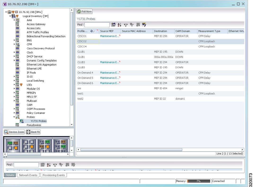
Table 17-2 describes the fields that are displayed in the content pane.
Step 3 ![]() Right-click on a probe and choose Properties to view its properties. Additionally, the following information is displayed in the Probe Properties window for a Cisco CPT device.
Right-click on a probe and choose Properties to view its properties. Additionally, the following information is displayed in the Probe Properties window for a Cisco CPT device.
Table 17-3 describes the additional fields that are displayed for a Cisco CPT device in the Probe Properties window.
Configuring Y.1731 Probes
You can configure Y.1731 probes using a certain set of commands. The following commands can be launched from the inventory by right-clicking the appropriate node and selecting Commands. Before executing any commands, you can preview them and view the results. If desired, you can also schedule the commands. To find out if a device supports these commands, see the Cisco Prime Network 3.10 Supported Cisco VNEs.
 Feedback