- Title Page
- Table of Contents
- Preface
- Setting Up Devices and Using the GUI Clients
- Working with the Cisco Prime Network Vision Client
- Viewing and Managing NE Properties
- Device Configurations and Software Images
- Working with Prime Network Vision Maps
- Working with Links
- Labeling NEs Using Business Tags
- Working with the Prime Network Events
- Tracking Faults Using Prime Network Events
- Working with Tickets in Cisco Prime Network Vision
- Working with Reports
- Using Cisco PathTracer to Diagnose Problems
- Monitoring Carrier Ethernet Services
- Monitoring Carrier Grade NAT Properties
- Monitoring DWDM Properties
- Monitoring Ethernet Operations, Administration,and Maintenance Tool Properties
- Monitoring Y.1731 IPSLA Configuration
- IPv6 and IPv6 VPN over MPLS
- Monitoring MPLS Services
- Viewing IP and MPLS Multicast Configurations
- Monitoring MToP Services
- Viewing and Managing SBCs
- Monitoring AAA Configurations
- Monitoring IP Pools
- Monitoring BNG Configurations
- Monitoring Mobile Technologies
- Monitoring Data Center Configurations
- Icon and Button Reference
- Glossary
- Index
Monitoring Ethernet Operations, Administration, and Maintenance Tool Properties
The following topics describe how you can use Cisco Prime Network Vision (Prime Network Vision) to monitor Ethernet operations, administration, and maintenance (OAM) tools:
•![]() User Roles Required to View Ethernet OAM Tool Properties
User Roles Required to View Ethernet OAM Tool Properties
•![]() Viewing Connectivity Fault Management Properties
Viewing Connectivity Fault Management Properties
•![]() Viewing Ethernet LMI Properties
Viewing Ethernet LMI Properties
User Roles Required to View Ethernet OAM Tool Properties
This topic identifies the roles that are required to view Ethernet OAM tool properties. Prime Network determines whether you are authorized to perform a task as follows:
•![]() For GUI-based tasks (tasks that do not affect elements), authorization is based on the default permission that is assigned to your user account.
For GUI-based tasks (tasks that do not affect elements), authorization is based on the default permission that is assigned to your user account.
•![]() For element-based tasks (tasks that do affect elements), authorization is based on the default permission that is assigned to your account. That is, whether the element is in one of your assigned scopes and whether you meet the minimum security level for that scope.
For element-based tasks (tasks that do affect elements), authorization is based on the default permission that is assigned to your account. That is, whether the element is in one of your assigned scopes and whether you meet the minimum security level for that scope.
For more information on user authorization, see the Cisco Prime Network 3.10 Administrator Guide.
The following tables identify the tasks that you can perform:
•![]() Table 16-1 identifies the tasks that you can perform if a selected element is not in one of your assigned scopes.
Table 16-1 identifies the tasks that you can perform if a selected element is not in one of your assigned scopes.
•![]() Table 16-2 identifies the tasks that you can perform if a selected element is in one of your assigned scopes.
Table 16-2 identifies the tasks that you can perform if a selected element is in one of your assigned scopes.
By default, users with the Administrator role have access to all managed elements. To change the Administrator user scope, see the topic on device scopes in the Cisco Prime Network 3.10 Administrator Guide.
Ethernet OAM Overview
Prime Network Vision supports three, interrelated OAM components, including:
•![]() Connectivity Fault Management—Connectivity Fault Management (CFM) is an end-to-end per-service-instance (per VLAN) Ethernet layer OAM protocol that includes connectivity monitoring, fault verification, and fault isolation. CFM allows you to manage individual customer service instances. Ethernet Virtual Connections (EVCs) are the services that are sold to customers and are designated by service VLAN tags. CFM operates on a per-service-VLAN (or per-EVC) basis. It lets you know when an EVC fails and provides tools to isolate the failure. See Viewing Connectivity Fault Management Properties and Configuring CFM.
Connectivity Fault Management—Connectivity Fault Management (CFM) is an end-to-end per-service-instance (per VLAN) Ethernet layer OAM protocol that includes connectivity monitoring, fault verification, and fault isolation. CFM allows you to manage individual customer service instances. Ethernet Virtual Connections (EVCs) are the services that are sold to customers and are designated by service VLAN tags. CFM operates on a per-service-VLAN (or per-EVC) basis. It lets you know when an EVC fails and provides tools to isolate the failure. See Viewing Connectivity Fault Management Properties and Configuring CFM.
•![]() Ethernet Local Management Interface—Ethernet Local Management Interface (Ethernet LMI) operates between the customer edge (CE) and the user-facing provider edge (U-PE) devices. Ethernet LMI allows you to automatically provision CEs based on EVCs and bandwidth profiles. See Viewing Ethernet LMI Properties and Configuring E-LMI.
Ethernet Local Management Interface—Ethernet Local Management Interface (Ethernet LMI) operates between the customer edge (CE) and the user-facing provider edge (U-PE) devices. Ethernet LMI allows you to automatically provision CEs based on EVCs and bandwidth profiles. See Viewing Ethernet LMI Properties and Configuring E-LMI.
•![]() Link OAM—Link OAM allows you to monitor and troubleshoot a single Ethernet link. It is an optional sublayer implemented in the Data Link Layer between the Logical Link Control (LLC) and MAC sublayers of the Open Systems Interconnect (OSI) model. You can monitor a link for critical events and, if needed, put a remote device into loopback mode for link testing. Link OAM also discovers unidirectional links, which are created when one transmission direction fails. See Viewing Link OAM Properties and Configuring L-OAM.
Link OAM—Link OAM allows you to monitor and troubleshoot a single Ethernet link. It is an optional sublayer implemented in the Data Link Layer between the Logical Link Control (LLC) and MAC sublayers of the Open Systems Interconnect (OSI) model. You can monitor a link for critical events and, if needed, put a remote device into loopback mode for link testing. Link OAM also discovers unidirectional links, which are created when one transmission direction fails. See Viewing Link OAM Properties and Configuring L-OAM.
Viewing Connectivity Fault Management Properties
CFM allows you to discover and verify end-to-end, Carrier Ethernet PE-to-PE or CE-to-CE paths through bridges and LANs.
CFM consists of maintenance domains. Maintenance domains are administrative regions used to manage and administer specific network segments. Maintenance domains are organized in a hierarchy. The administrator assigns a maintenance level to the domain from 0 (lowest level) to 7 (highest level); the maintenance level determines the domain's position within the CFM hierarchy.
CFM maintenance domain boundaries are indicated by maintenance points. A maintenance point is an interface point that participates within a CFM maintenance domain. Maintenance point types include:
•![]() Maintenance Endpoints—Maintenance endpoints (MEPs) are active CFM elements residing at the edge of a domain. MEPs can be inward or outward facing. They periodically transmit continuity check messages and expect to periodically receive similar messages from other MEPs within a domain. If requested, MEPs can also transmit traceroute and loopback messages. MEPs are responsible for keeping CFM messages within the boundaries of a maintenance domain.
Maintenance Endpoints—Maintenance endpoints (MEPs) are active CFM elements residing at the edge of a domain. MEPs can be inward or outward facing. They periodically transmit continuity check messages and expect to periodically receive similar messages from other MEPs within a domain. If requested, MEPs can also transmit traceroute and loopback messages. MEPs are responsible for keeping CFM messages within the boundaries of a maintenance domain.
•![]() Maintenance Intermediate Points—Maintenance intermediate points (MIPs) are passive elements that catalog information received from MEPs and other MIPs. MIPs only respond to specific CFM messages such as traceroute and loopback, and they forward those messages within the maintenance domain.
Maintenance Intermediate Points—Maintenance intermediate points (MIPs) are passive elements that catalog information received from MEPs and other MIPs. MIPs only respond to specific CFM messages such as traceroute and loopback, and they forward those messages within the maintenance domain.

Note ![]() Prime Network Vision does not display information for CFM maintenance endpoints or maintenance intermediate points for Cisco Viking devices if errors exist in their configurations. An error in the configuration is indicated by an exclamation point (!) in the CLI output.
Prime Network Vision does not display information for CFM maintenance endpoints or maintenance intermediate points for Cisco Viking devices if errors exist in their configurations. An error in the configuration is indicated by an exclamation point (!) in the CLI output.
For example, if you enter the command show ethernet cfm local maintenance-points, a configuration error is indicated as follows:cfm_d100/2 cfm_s100 Te0/2/0/3.110 Up MEP 2100 eb:7a:53!
CFM uses standard Ethernet frames. CFM frames are distinguishable by EtherType and for multicast messages, by MAC address. CFM frames are sourced, terminated, processed, and relayed by bridges. Routers support only limited CFM functions.
Bridges that cannot interpret CFM messages forward them as normal data frames. All CFM messages are confined to a maintenance domain and to an S-VLAN (PE-VLAN or Provider-VLAN). CFM supports three types of messages:
•![]() Continuity check—Multicast heartbeat messages exchanged periodically among MEPs. They allow MEPs to discover other MEPs within a domain and allow maintenance intermediate points (MIPs) to discover MEPs. Continuity check messages (CCMs) are confined to a domain and S-VLAN.
Continuity check—Multicast heartbeat messages exchanged periodically among MEPs. They allow MEPs to discover other MEPs within a domain and allow maintenance intermediate points (MIPs) to discover MEPs. Continuity check messages (CCMs) are confined to a domain and S-VLAN.
•![]() Loopback—Unicast frames that a MEP transmits, at the request of an administrator, to verify connectivity to a particular maintenance point. A reply to a loopback message indicates whether a destination is reachable but does not allow hop-by-hop discovery of the path. A loopback message is similar in concept to an Internet Control Message Protocol (ICMP) Echo (ping) message.
Loopback—Unicast frames that a MEP transmits, at the request of an administrator, to verify connectivity to a particular maintenance point. A reply to a loopback message indicates whether a destination is reachable but does not allow hop-by-hop discovery of the path. A loopback message is similar in concept to an Internet Control Message Protocol (ICMP) Echo (ping) message.
•![]() Traceroute—Multicast frames that a MEP transmits, at the request of an administrator, to track the path (hop-by-hop) to a destination MEP. They allow the transmitting node to discover vital connectivity data about the path, and allow the discovery of all MIPs along the path that belong to the same maintenance domain. For each visible MIP, traceroute messages indicate ingress action, relay action, and egress action. Traceroute messages are similar in concept to User Datagram Protocol (UDP) traceroute messages.
Traceroute—Multicast frames that a MEP transmits, at the request of an administrator, to track the path (hop-by-hop) to a destination MEP. They allow the transmitting node to discover vital connectivity data about the path, and allow the discovery of all MIPs along the path that belong to the same maintenance domain. For each visible MIP, traceroute messages indicate ingress action, relay action, and egress action. Traceroute messages are similar in concept to User Datagram Protocol (UDP) traceroute messages.
From the Logical Inventory tree, you can troubleshoot MEPs using CFM ping, traceroute, MEP status, and MEP cross-check status. These commands, and all CFM commands, are described in Configuring CFM.
Prime Network associates alarms with the corresponding MEP or global CFM logical inventory objects. Prime Network correlates MEP down, MEP up, MEP missing, ETH-AIS, and ETH-RDI events with root cause alarms and corresponding tickets that exist along the path between the MEP on the reporting network element and the network element hosting the remote MEP.
To view CFM properties:
Step 1 ![]() In Prime Network Vision, double-click the required device for CFM.
In Prime Network Vision, double-click the required device for CFM.
Step 2 ![]() In the inventory window, choose Logical Inventory > CFM.
In the inventory window, choose Logical Inventory > CFM.
Figure 16-1 shows an example of CFM in logical inventory.
Figure 16-1 CFM in Logical Inventory

Table 16-3 describes the information displayed for CFM.
Step 3 ![]() Click the Maintenance Intermediate Points tab to view MIP information. See Figure 16-2.
Click the Maintenance Intermediate Points tab to view MIP information. See Figure 16-2.
Figure 16-2 CFM Maintenance Intermediate Points Tab
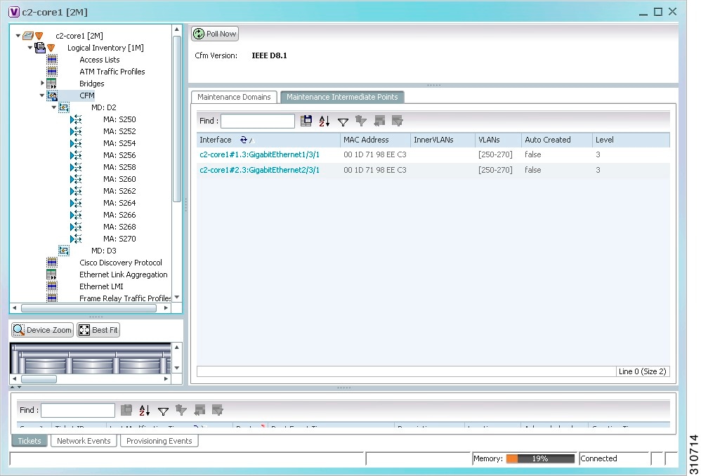
Table 16-4 describes the information that is displayed in the Maintenance Intermediate Points table.
Step 4 ![]() To view the details of a specific maintenance domain, do one of the following:
To view the details of a specific maintenance domain, do one of the following:
•![]() Choose Logical Inventory > CFM > domain.
Choose Logical Inventory > CFM > domain.
•![]() Double-click the required entry in the Maintenance Domains table.
Double-click the required entry in the Maintenance Domains table.
Figure 16-3 shows an example of the information displayed for the maintenance domain.
Figure 16-3 CFM Maintenance Domain Properties
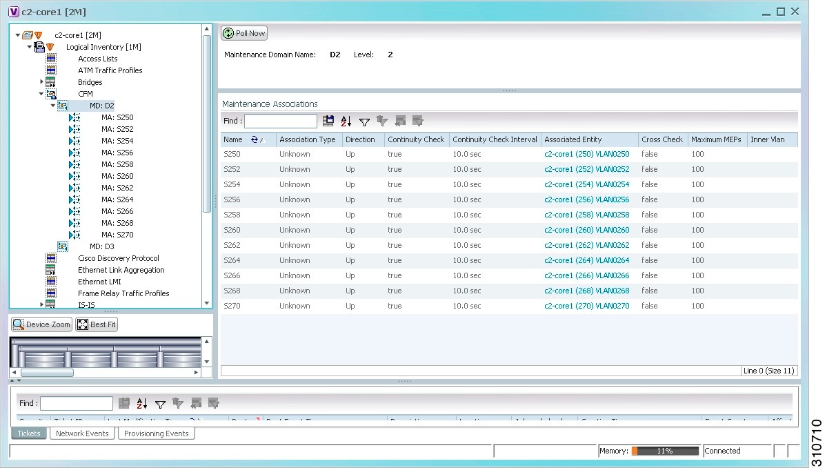
Table 16-5 describes the information that is displayed for CFM maintenance domains.
Step 5 ![]() To view the properties for a maintenance association's endpoints, do one of the following:
To view the properties for a maintenance association's endpoints, do one of the following:
•![]() Choose Logical Inventory > CFM > domain > association.
Choose Logical Inventory > CFM > domain > association.
•![]() In the Maintenance Associations table, double-click the required association.
In the Maintenance Associations table, double-click the required association.
Figure 16-4 shows the information displayed for the maintenance association endpoints.
Figure 16-4 CFM Maintenance Association - Endpoint Properties
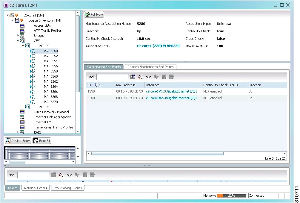
Table 16-6 describes the information that is displayed for CFM maintenance associations and MIPs.
Step 6 ![]() Click the Remote Maintenance End Points tab to view the information displayed for remote MEPs. See Figure 16-5.
Click the Remote Maintenance End Points tab to view the information displayed for remote MEPs. See Figure 16-5.
Figure 16-5 Remote Maintenance End Points Table
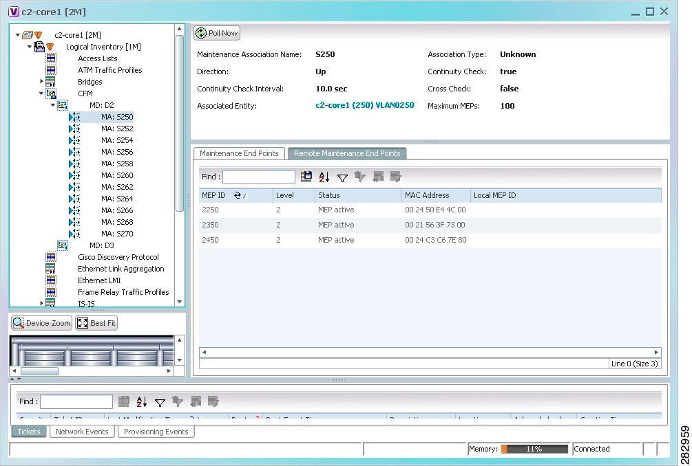
Table 16-7 describes the information presented for remote MEPs.
Viewing Ethernet LMI Properties
Ethernet Local Management Interface (E-LMI) is a protocol that operates between the customer edge (CE) network element and the provider edge (PE) network element. Ethernet LMI is a protocol between the CE network element and the provider edge (PE) network element. It runs only on the PE-CE UNI link and notifies the CE of connectivity status and configuration parameters of Ethernet services available on the CE port. Ethernet LMI interoperates with an OAM protocol, such as CFM, that runs within the provider network to collect OAM status. CFM runs at the provider maintenance level. Ethernet LMI relies on the OAM Ethernet Infrastructure (EI) to work with CFM for end-to-end status of EVCs across CFM domains. E-LMI commands are described in Configuring E-LMI.
The IOS OAM manager streamlines interaction between OAM protocols, and handles the interaction between CFM and E-LMI. Ethernet LMI interaction with the OAM manager is unidirectional, running only from the OAM manager to E-LMI on the U-PE side of the switch. Information is exchanged either as a result of a request from E- LMI or triggered by the OAM manager when it receives notification of a change from the OAM protocol. Information that is relayed includes the EVC name and availability status, remote UNI name and status, and remote UNI counts.
To view Ethernet LMI properties:
Step 1 ![]() In Prime Network Vision, double-click the device configured for Ethernet LMI.
In Prime Network Vision, double-click the device configured for Ethernet LMI.
Step 2 ![]() In the inventory window, choose Logical Inventory > Ethernet LMI.
In the inventory window, choose Logical Inventory > Ethernet LMI.
Figure 16-6 shows an example of Ethernet LMI properties in logical inventory.
Figure 16-6 Ethernet LMI in Logical Inventory
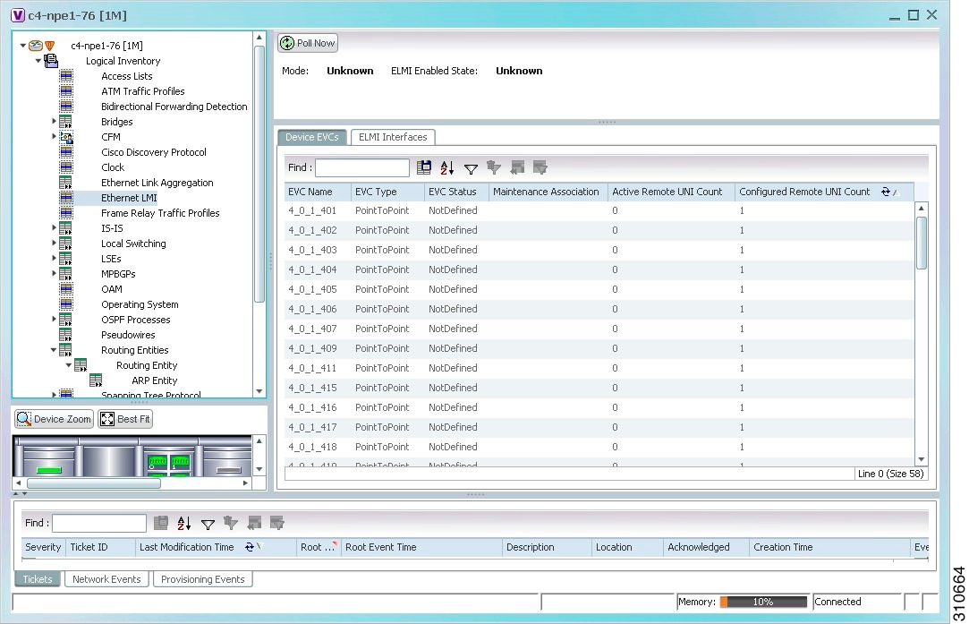
Table 16-8 describes the information displayed for Ethernet LMI.
|
|
|
|---|---|
Globally Enabled |
Whether or not Ethernet LMI is enabled globally: True or False. |
Mode |
Ethernet LMI mode: CE or PE. |
|
|
|
EVC Name |
Name of the EVC. |
EVC Type |
Type of EVC: Point-to-point or Multipoint. |
EVC Status |
EVC status: Active, Inactive, Not Defined, or Partially Active. |
Maintenance Association |
Hyperlinked entry to the maintenance association in CFM in logical inventory. For more information about maintenance associations, see Table 16-6. |
Active Remote UNI Count |
Number of active remote UNIs. |
Configured Remote UNI Count |
Number of configured remote UNIs. |
|
|
|
Interface Name |
Hyperlinked entry to the interface in physical inventory. For more information, see Step 4 in this procedure. |
T391 |
Frequency at which the customer equipment sends status inquiries. The range is 5-30 seconds, with a default of 10 seconds. |
T392 |
Frequency at which the metro Ethernet network verifies that status enquiries have been received. The range is 5-30 seconds, with a default of 15 seconds. A value of 0 (zero) indicates the timer is disabled. |
N391 |
Frequency at which the customer equipment polls the status of the UNI and all EVCs. The range is 1-65000 seconds, with a default of 360 seconds. |
N393 |
Error count for the metro Ethernet network. The range is 1-10, with a default of 4. |
Step 3 ![]() To view device EVC properties, double-click an EVC name in the Device EVCs tab.
To view device EVC properties, double-click an EVC name in the Device EVCs tab.
The Device EVC Properties window is displayed as shown in Figure 16-7.
Figure 16-7 Device EVC Properties Window
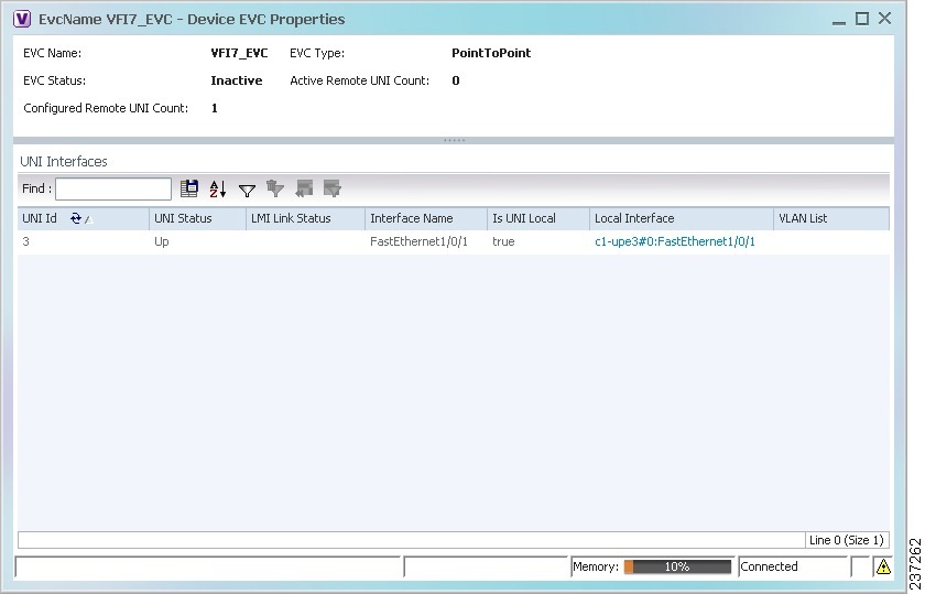
Table 16-9 describes the information displayed in the Device EVC Properties window.
|
|
|
|---|---|
EVC Name |
Name of the EVC. |
EVC Type |
Type of EVC: Point-to-point or Multipoint. |
EVC Status |
EVC status: Active, Inactive, Not Defined, or Partially Active. |
Maintenance Association |
Hyperlinked entry to the maintenance association in CFM in logical inventory. For more information about maintenance associations, see Table 16-6. |
Active Remote UNI Count |
Number of active remote UNIs. |
Configured Remote UNI Count |
Number of configured remote UNIs. |
|
|
|
UNI Id |
UNI identifier. |
UNI Status |
Status of the UNI: Up or Down. |
LMI Link Status |
Status of the LMI link: Up or Down. |
Interface Name |
Interface on which UNI is configured. |
Is UNI Local |
Whether or not UNI is local: True or False. |
Local Interface |
Hyperlinked entry to the interface in physical inventory. |
VLAN List |
Name of the VLAN associated with the UNI interface. |
Step 4 ![]() To view properties for an Ethernet LMI interface in physical interface, click the required interface name in the ELMI Interfaces table.
To view properties for an Ethernet LMI interface in physical interface, click the required interface name in the ELMI Interfaces table.
Table 16-10 describes the information displayed in the UNI Properties area in physical inventory.
Viewing Link OAM Properties
Link OAM is an optional sublayer implemented in the OSI Data Link Layer between the Logical Link Control and MAC sublayers. Link (802.3AH) OAM (L-OAM) can be implemented on any full-duplex point-to-point or emulated point-to-point Ethernet link.
The frames (OAM Protocol Data Units [OAMPDUs]) cannot propagate beyond a single hop within an Ethernet network and have modest bandwidth requirements (frame transmission rate is limited to a maximum of 10 frames per second).
Link OAM processes include:
•![]() Discovery—Discovery is the first Link OAM process. During discovery, Link OAM identifies the devices at each end of the link and learns their OAM capabilities.
Discovery—Discovery is the first Link OAM process. During discovery, Link OAM identifies the devices at each end of the link and learns their OAM capabilities.
•![]() Link monitoring—Link OAM link monitoring includes:
Link monitoring—Link OAM link monitoring includes:
–![]() Monitoring links and issuing notifications when error thresholds are exceeded or faults occur.
Monitoring links and issuing notifications when error thresholds are exceeded or faults occur.
–![]() Collecting statistics on the number of frame errors (or percent of frames that have errors) and the number of coding symbol errors.
Collecting statistics on the number of frame errors (or percent of frames that have errors) and the number of coding symbol errors.
•![]() Remote MIB Variable Retrieval—Provides 802.3ah MIB polling and response (but not writing).
Remote MIB Variable Retrieval—Provides 802.3ah MIB polling and response (but not writing).
•![]() Remote Failure indication—Informs peers when a received path goes down. Because link connectivity faults caused by slowly deteriorating quality are difficult to detect, Link OAM communicates such failure conditions to its peer using OAMPDU flags. The failure conditions that can be communicated are a loss of signal in one direction on the link, an unrecoverable error (such as a power failure), or some other critical event.
Remote Failure indication—Informs peers when a received path goes down. Because link connectivity faults caused by slowly deteriorating quality are difficult to detect, Link OAM communicates such failure conditions to its peer using OAMPDU flags. The failure conditions that can be communicated are a loss of signal in one direction on the link, an unrecoverable error (such as a power failure), or some other critical event.
•![]() Remote Loopback—Puts the peer device in (near-end) intrusive loopback mode using the OAMPDU loopback control. Statistics can be collected during the link testing. In loopback mode, every frame received is transmitted back unchanged on the same port (except for OAMPDUs, which are needed to maintain the OAM session). Loopback mode helps ensure the quality of links during installation or troubleshooting. Loopback mode can be configured so that the service provider device can put the customer device into loopback mode, but the customer device cannot put the service provider device in loopback mode.
Remote Loopback—Puts the peer device in (near-end) intrusive loopback mode using the OAMPDU loopback control. Statistics can be collected during the link testing. In loopback mode, every frame received is transmitted back unchanged on the same port (except for OAMPDUs, which are needed to maintain the OAM session). Loopback mode helps ensure the quality of links during installation or troubleshooting. Loopback mode can be configured so that the service provider device can put the customer device into loopback mode, but the customer device cannot put the service provider device in loopback mode.
Prime Network Vision supports topology discovery based on Link OAM information and enables you to view Link OAM properties. You can also configure L-OAM using the commands described in Configuring L-OAM.
For information on CFM and Ethernet LMI, see Viewing Connectivity Fault Management Properties and Viewing Ethernet LMI Properties.
To view Link OAM properties:
Step 1 ![]() In Prime Network Vision, double-click the device configured for Link OAM.
In Prime Network Vision, double-click the device configured for Link OAM.
Step 2 ![]() In the inventory window, choose Logical Inventory > OAM.
In the inventory window, choose Logical Inventory > OAM.
Figure 16-8 shows an example of Link OAM properties in logical inventory.
Figure 16-8 Link OAM Properties in Logical Inventory
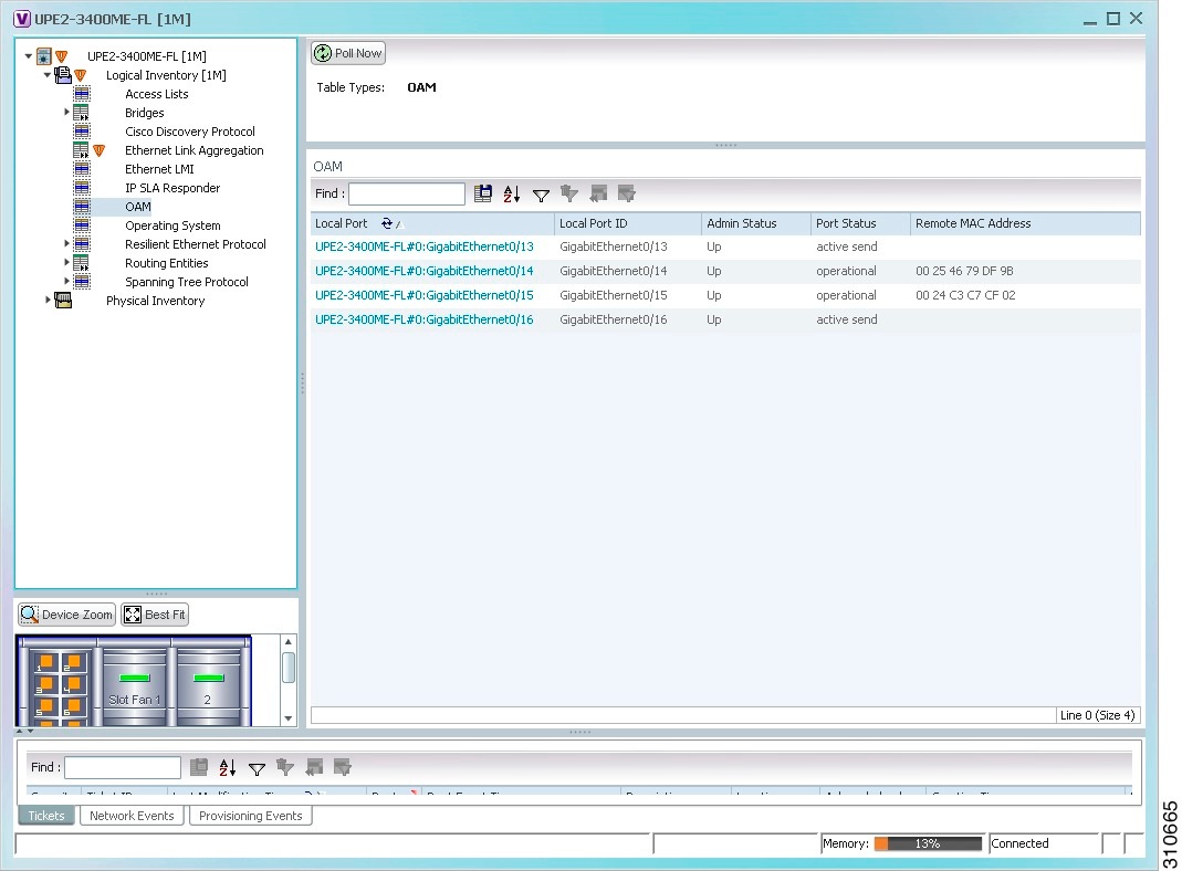
Table 16-11 describes the information displayed for Link OAM.
Step 3 ![]() To view detailed information about an entry in the table, double-click the required entry.
To view detailed information about an entry in the table, double-click the required entry.
The Link OAM Data Properties window is displayed as shown in Figure 16-9.
Figure 16-9 Link OAM Data Properties Window
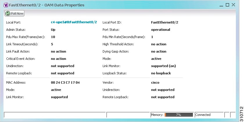
Table 16-12 describes the information that is displayed in the Link OAM Data Properties window.
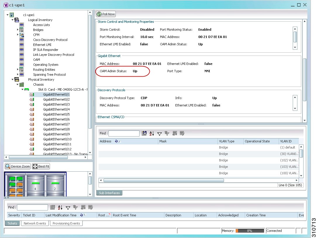
Step 4 ![]() To view Link OAM status in physical inventory, choose Physical Inventory > chassis > slot > interface.
To view Link OAM status in physical inventory, choose Physical Inventory > chassis > slot > interface.
The Link OAM administrative status is displayed as shown in Figure 16-10.
Figure 16-10 Link OAM Administrative Status in Physical Inventory
Configuring CFM
CFM provides capabilities for detecting, verifying, and isolating connectivity failures in networks with bridges operated by multiple independent organizations, each with restricted management access to each other's equipment.
The CFM commands can be launched from the inventory by right-clicking a CFM node and selecting Commands. Unless otherwise noted, all of the following commands are launched by right-clicking the device and choosing Commands > Configure > Cisco. You can navigate from the MEP logical inventory to the interface or port channel on which the MEP is configured.
To run the these commands, the software on the network element must support the technology. Before executing any commands, you can preview them and view the results. If desired, you can also schedule the commands.
For details on the software versions Prime Network supports for the listed supported network elements, see Cisco Prime Network 3.10 Supported Cisco VNEs.
You might be prompted to enter your device access credentials while executing a command. Once you have entered them, these credentials will be used for every subsequent execution of a command in the same GUI client session. If you want to change the credentials, click Edit Credentials. The Edit Credentials button will not be available for SNMP commands or if the command is scheduled for a later time.
|
|
|
|
|---|---|---|
Maintenance Domain > Configure CFM Maintenance Domain |
A maintenance domain is a management space for the purpose of managing and administering a network. A single entity owns and operates a domain and is defined by the set of ports internal to it and at its boundary. Each maintenance domain can contain any number of maintenance associations. Each maintenance association identifies a service that can be uniquely identified within the maintenance domain. The CFM protocol runs within a particular maintenance association. Using this command, assign a unique maintenance level to each domain and a maintenance endpoint archived hold time. Maintenace level defines the hierarchical relationship among domains and MEP Archive Hold time acts as a demarcation point on an interface that participates in CFM. |
• • • • • • • • • • • • • • • |
Global Parameters > Configure CFM Global Parameters |
Enable CFM globally for a network element. Using this command you can configure the device to transmit traceroute and loopback messages with a hold-time value that indicates the validity of the messages. |
|
Enable > Cisco >Continuity Check > Configure CFM Continuity Check Enable > Cisco >Continuity Check > Enable CFM Continuity Check |
Enable continuity check parameters on the specified domain, service1 , bridge group, and bridge domain names. |
• • • • • • • • • • • • • • • |
MIP > Configure CFM MIP |
The Configure CFM MIP command configures an operator-level maintenance intermediate point (MIP) for the domain-level ID. If the port on which a MIP is configured is blocked by Spanning-Tree Protocol (STP), the MIP cannot receive CFM messages or relay them toward the relay function side. The MIP can, however, receive and respond to CFM messages from the wire. A MIP has only one level associated with it, and the command-line interface (CLI) does not allow you to configure a MIP for a domain that does not exist. Note |
|
Service ID > Configure CFM Service ID |
Use the Configure CFM Service ID command to configure the CFM service ID. |
|
MEP > Configure CFM MEP |
Use this command to configure maintenance endpoints (MEPs), which have the following characteristics: • • • • • Note |
• • • • • • • • • • • • • • • |
Enable > Cisco > SNMP Server Traps > Enable CFM SNMP Server Traps |
Enables Ethernet CFM continuity check traps and Ethernet CFM cross-check traps |
1 Applicable for Cisco ASR 9000 series that run on Cisco IOS XR software. |
Configuring E-LMI
E-LMI notifies the CE of connectivity status and configuration parameters of Ethernet services available on the CE port.
The following commands can be launched from the inventory by right-clicking an E-LMI node and selecting Commands. Before executing any commands, you can preview them and view the results. If desired, you can also schedule the commands. The table below lists the Ethernet LMI commands and the supported network elements.
To run the these commands, the software on the network element must support the technology. Before executing any commands, you can preview them and view the results. If desired, you can also schedule the commands.
For details on the software versions Prime Network supports for the listed supported network elements, see Cisco Prime Network 3.10 Supported Cisco VNEs.
You might be prompted to enter your device access credentials while executing a command. Once you have entered them, these credentials will be used for every subsequent execution of a command in the same GUI client session. If you want to change the credentials, click Edit Credentials. The Edit Credentials button will not be available for SNMP commands or if the command is scheduled for a later time.
Configuring L-OAM
L-OAM commands monitors and troubleshoots a single Ethernet link. The following commands can be launched from the inventory by right-clicking a L-OAM node and selecting Commands. Before executing any commands, you can preview them and view the results. If desired, you can also schedule the commands. The table below lists the L-OAM commands.
To run the these commands, the software on the network element must support the technology. Before executing any commands, you can preview them and view the results. If desired, you can also schedule the commands.
For details on the software versions Prime Network supports for the listed supported network elements, see Cisco Prime Network 3.10 Supported Cisco VNEs.
You might be prompted to enter your device access credentials while executing a command. Once you have entered them, these credentials will be used for every subsequent execution of a command in the same GUI client session. If you want to change the credentials, click Edit Credentials. The Edit Credentials button will not be available for SNMP commands or if the command is scheduled for a later time.
 Feedback