- Title Page
- Table of Contents
- Preface
- Setting Up Devices and Using the GUI Clients
- Working with the Cisco Prime Network Vision Client
- Viewing and Managing NE Properties
- Device Configurations and Software Images
- Working with Prime Network Vision Maps
- Working with Links
- Labeling NEs Using Business Tags
- Working with the Prime Network Events
- Tracking Faults Using Prime Network Events
- Working with Tickets in Cisco Prime Network Vision
- Working with Reports
- Using Cisco PathTracer to Diagnose Problems
- Monitoring Carrier Ethernet Services
- Monitoring Carrier Grade NAT Properties
- Monitoring DWDM Properties
- Monitoring Ethernet Operations, Administration,and Maintenance Tool Properties
- Monitoring Y.1731 IPSLA Configuration
- IPv6 and IPv6 VPN over MPLS
- Monitoring MPLS Services
- Viewing IP and MPLS Multicast Configurations
- Monitoring MToP Services
- Viewing and Managing SBCs
- Monitoring AAA Configurations
- Monitoring IP Pools
- Monitoring BNG Configurations
- Monitoring Mobile Technologies
- Monitoring Data Center Configurations
- Icon and Button Reference
- Glossary
- Index
- Overview of the GUI Clients
- Setting Up Devices and Validating Device Information
- Configure Basic Device Settings: Name, DNS, NTP, RADIUS, TACACs, ACLs
- Configure SNMP and SNMP Traps on Device
- Configure Device Ports and Interfaces
- View Device and VRF Routing Tables and Device Interface Briefs
- Ping Destinations and VRFs, and View Trace Route from Device
- Change Device Syslog Logging Level
- View, Copy, and Overwrite Device Configuration Files
- View Users (Telnet Sessions) on Device
- Using Prime Network with Prime Central
Setting Up Devices and Using the GUI Clients
These topics introduce you to the Cisco Prime Network GUI clients:
•![]() Setting Up Devices and Validating Device Information
Setting Up Devices and Validating Device Information
•![]() Using Prime Network with Prime Central
Using Prime Network with Prime Central
Overview of the GUI Clients
Cisco Prime Network (Prime Network) provides the following GUI clients that offer an intuitive interface for managing your network and services, and for performing required system administration activities:
Prime Network Vision
Prime Network Vision is the main GUI client for Prime Network. Maps of devices create a visualization of the network, from the intricacies of a single device physical and logical inventory, to multi-layer topological information on connections, traffic, and routes. Faults and alarms are graphically displayed with built-in troubleshooting tools. Network elements and links using color cues and graphic symbols to indicate status and alarms.
All user actions are controlled by user roles and device scopes. Each user is assigned a role which controls the GUI actions the user can perform. When a user does not have the required permission level to perform a function, the appropriate menu option or button is disabled. Similarly, device scopes, which are named collections of managed network elements, control which devices a user can access. User roles and device scopes are controlled from the Prime Network Administration GUI client.
Prime Network Vision is also the launching point for these features.
For more information on the Prime Network Vision GUI client, see Working with the Cisco Prime Network Vision Client.
Prime Network Events
Prime Network Events is the interface used by system managers and administrators for viewing system events that occur in the network. You can use the GUI to retrieve detailed information about the different types of system events and tickets that are generated; it also helps predict and identify the sources of system problems. The GUI client also provides information about events within the Prime Network system. For more information, see Working with the Prime Network Events Client.
Prime Network Administration
Prime Network Administration is the GUI client used to manage the Prime Network system, which is comprised of gateway servers, units, AVMs, and VNEs. These components work together to create the information model, which is constantly updated. Administrators use this GUI client to create user accounts, device scopes, polling groups, redundancy settings, and so forth. For information on this GUI client, see the Cisco Prime Network 3.10 Administrator Guide.
Setting Up Devices and Validating Device Information
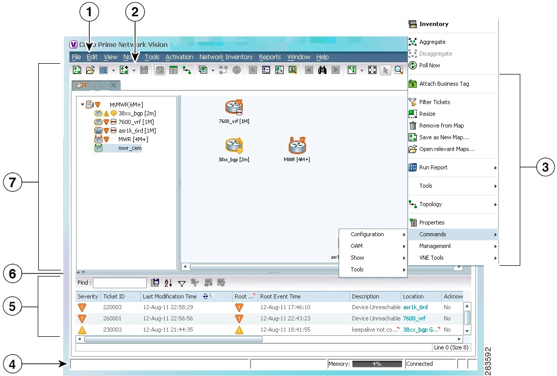
Prime Network provides a variety of management and configuration commands that you can launch from the Vision GUI client by right-clicking an NE and selecting Commands. These commands are executed on the actual physical device versus being performed on the network model that is stored in memory (and subsequently on the real device). This is useful to validate information displayed in a Prime Network GUI client against a device, using the device command line interface (CLI). Before executing any commands, you can preview them and view the results. If desired, you can also schedule the commands, if you have user permissions to do so.
Prime Network also provides a variety of technology-specific commands—such as configuring the clock source for signals on SONET ports, enabling global ELM-I, enabling OAM on an interface. Whether you can use these commands depends on whether the technology is enabled on the device.

Note ![]() The basic operation commands in this chapter can be executed by all network elements that run on Cisco IOS software, Cisco IOS XR software, and Cisco NX OS software. You will not be able to execute these commands on network elements that have Cisco Catalyst OS software.
The basic operation commands in this chapter can be executed by all network elements that run on Cisco IOS software, Cisco IOS XR software, and Cisco NX OS software. You will not be able to execute these commands on network elements that have Cisco Catalyst OS software.
Note ![]() To view the basic operation commands in the Cisco Carrier Packet Transport (CPT) System, you must right-click the Cisco Carrier Packet Transport (CPT) System in the Prime Network Vision List or Map View and click Logical Inventory > CPT Context Container.
To view the basic operation commands in the Cisco Carrier Packet Transport (CPT) System, you must right-click the Cisco Carrier Packet Transport (CPT) System in the Prime Network Vision List or Map View and click Logical Inventory > CPT Context Container.
Execution of command builder scripts will fail under Managed Element and Physical Root
Figure 1-1 illustrates how to launch these commands.
Figure 1-1 Launching NE Management and Configuration Commands
|
|
Menu Bar |
|
Ticket Pane |
|
|
Tool bar |
|
Hide/display Ticket Pane |
|
|
Device Right-click Menu |
|
Navigation Pane |
|
|
Status Bar |
Note ![]() You might be prompted to enter your device access credentials. Once you have entered them, these credentials will be used for every subsequent execution of a command in the same GUI client session. If you want to change the credentials, click Edit Credentials. The Edit Credentials button will not be available for SNMP commands or if the command is scheduled for a later time.
You might be prompted to enter your device access credentials. Once you have entered them, these credentials will be used for every subsequent execution of a command in the same GUI client session. If you want to change the credentials, click Edit Credentials. The Edit Credentials button will not be available for SNMP commands or if the command is scheduled for a later time.
These topics describe the available commands:
•![]() Configure Basic Device Settings: Name, DNS, NTP, RADIUS, TACACs, ACLs
Configure Basic Device Settings: Name, DNS, NTP, RADIUS, TACACs, ACLs
•![]() Configure SNMP and SNMP Traps on Device
Configure SNMP and SNMP Traps on Device
•![]() Configure Device Ports and Interfaces
Configure Device Ports and Interfaces
•![]() View Device and VRF Routing Tables and Device Interface Briefs
View Device and VRF Routing Tables and Device Interface Briefs
•![]() Ping Destinations and VRFs, and View Trace Route from Device
Ping Destinations and VRFs, and View Trace Route from Device
•![]() Change Device Syslog Logging Level
Change Device Syslog Logging Level
•![]() View, Copy, and Overwrite Device Configuration Files
View, Copy, and Overwrite Device Configuration Files
•![]() View Users (Telnet Sessions) on Device
View Users (Telnet Sessions) on Device
Configure Basic Device Settings: Name, DNS, NTP, RADIUS, TACACs, ACLs
Use the following commands to configure system-level settings on the real device. Unless otherwise noted, all of the following commands are launched by right-clicking the device and choosing Commands > Configuration > System.
Configure the Device Host Name and DNS
Configure a Device NTP Server
|
|
|
|---|---|
NTP > Add NTP Server NTP > Remove NTP Server |
Assigns the device to a Network Time Protocol (NTP) server to manage clock synchronization. |
Configure RADIUS or TACACS Server on Device
Configure IP Access Control Lists (ACL) on Device
Configure SNMP and SNMP Traps on Device
Use the following commands to configure SNMP settings and SNMP traps on the real device. All of the following commands are launched by right-clicking the device and choosing Commands > Configuration > System.
Configure Device Ports and Interfaces
Configure Device Ports
Note ![]() To apply description or status changes to an interface and port at the same time, use the interface commands listed in Configure Device Interfaces.
To apply description or status changes to an interface and port at the same time, use the interface commands listed in Configure Device Interfaces.
Configure Device Interfaces
View Device and VRF Routing Tables and Device Interface Briefs
View Interface Briefs and IP Routes
Ping Destinations and VRFs, and View Trace Route from Device
Change Device Syslog Logging Level
.
View, Copy, and Overwrite Device Configuration Files
View Users (Telnet Sessions) on Device
|
|
|
|
|---|---|---|
Users (Telnet Sessions) |
NE > Commands > Show |
Provides details about the device's current Telnet sessions. |
Using Prime Network with Prime Central
Prime Network can be installed as a standalone product or with Cisco Prime Central. When installed with Cisco Prime Central, you can launch Prime Network GUI clients from the Cisco Prime Portal. Cross-launch to and from other suite applications is also supported. The applications share a common inventory.
The Cisco Prime Portal uses a single sign-on (SSO) mechanism so that users need not reauthenticate with each GUI client. All session management features are controlled by the portal (such as client timeouts). If a user tries to log into a standalone GUI client, the user will be redirected to the portal login. The only exception is the emergency user, who will still be allowed to log into a standalone GUI client.
If the Cisco Prime Performance Manager application is also installed, the Prime Network Event Collector will receive threshold crossing alarm (TCA) events from Prime Performance Manager components and generate a ticket that you can view in Prime Network Events.
Prime Network also receives EPM-MIB traps from the network. By default Prime Network receives EPM-MIB traps from any source in the network. If desired, you can configure Prime Network to only process EPM-MIB traps arriving from a specific Prime Performance Manager server. The instructions for doing this are provided on the Cisco Developer Network at http://developer.cisco.com/web/prime-network/home.
 Feedback