Outlines the internal system behavior and workflow of VOQ-based packet forwarding. It describes how components like ingress interfaces, virtual output queues, and egress schedulers coordinate to ensure efficient, lossless traffic transmission across the switch fabric.
Summary
The key components involved in VOQ-based traffic management are:
-
Ingress Interface: Classifies, marks, and polices incoming data packets. The ingress interface is always mapped to a physical port.
-
Ingress VOQ: Buffers packets based on egress port and traffic class; instantiated dynamically when traffic is present. Every ingress interface port maintains eight VOQs—one for each traffic class—dedicated to a specific egress port.
-
Connectors: Logical links between ingress NPUs and egress ports that handle credit requests, grant responses, and data transmission across the fabric cards.
-
Egress Scheduler: Allocates credits based on available bandwidth and priority policies.
-
Egress Interface: Applies final markings and transmits packets to the next hop. The egress interface is always mapped to a physical port.
Traffic management with VOQs involves a coordinated sequence of queuing and scheduling actions between ingress and egress components to ensure efficient and lossless packet forwarding. The key components—ingress interface, Virtual Output Queues (VOQs), connector mesh, egress scheduler, and egress interface—work together to classify incoming traffic, buffer it per egress destination, allocate transmission credits based on availability, and transmit packets across the switch fabric with minimal latency and packet loss.
Workflow
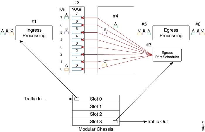
Theses stages describe how traffic management with VOQs work.
-
The ingress interface classifies and marks incoming packets.
The router receives packets—A (green), B (pink), and C (brown)—on the ingress interface. This is where packet marking, classification, and policing are applied based on QoS policies.
This diagram illustrates a modular chassis with multiple slots (Slot 0 to Slot 3).
-
The ingress interface maps packets to dedicated VOQs.
Per traffic-class, each packet is enqueued into a VOQ corresponding to its egress port. For example, in the figure:
-
Packet A (green) is mapped to TC7,
-
Packet B (pink) is mapped to TC5, and
-
Packet C (brown) is mapped to TC0.
This one-to-one VOQ mapping ensures proper congestion management and accurate scheduling for each flow.
-
-
The egress scheduler allocates transmission credits.
Based on the availability of egress bandwidth, the egress port scheduler issues credits that determine the sequence and rate of packet transmission towards the egress interface.
-
The fabric switch forwards eligible packets to the egress port.
Once credits are received, the eligible packets are transmitted across the fabric card toward the appropriate egress port.
-
The egress interface marks and prepares packets for forwarding.
At the egress interface, any final packet markings or required shaping is enforced before forwarding to the next hop.
-
The router transmits packets to their outbound destination.
At this stage, congestion is managed in such a way that no packets are dropped, and all packets are transmitted to the next hop.