Configure VXLAN EVPN Multi-Site

This chapter contains these sections:

VXLAN EVPN multi-sites

A VXLAN EVPN multi-site is a data center network solution that

  • interconnects two or more BGP-based Ethernet VPN (EVPN) sites or overlay domains over an IP-only network,

  • uses border gateways (BGWs) in anycast or vPC mode to terminate and interconnect sites, and

  • enforces scalable traffic control and failure containment across domains.

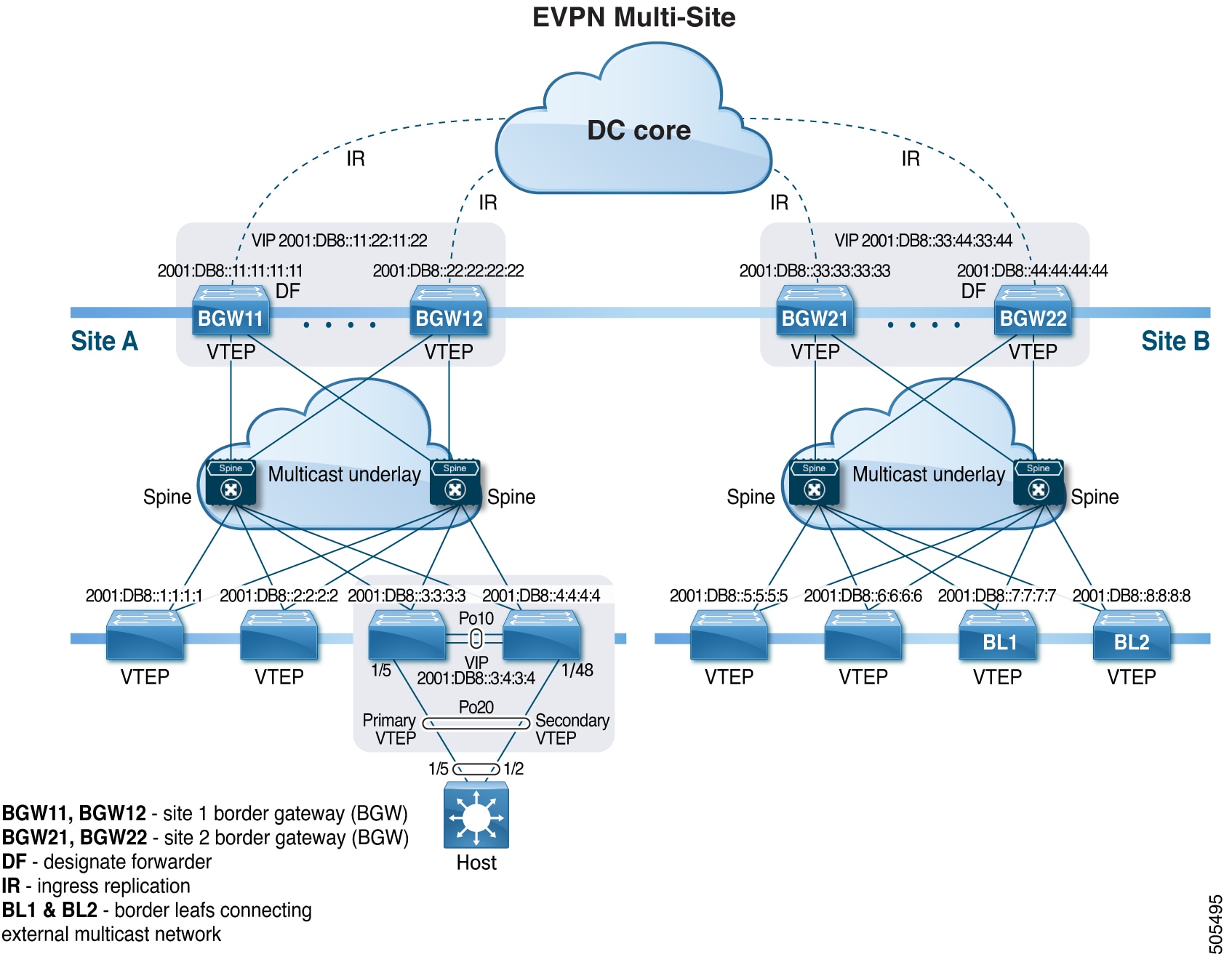
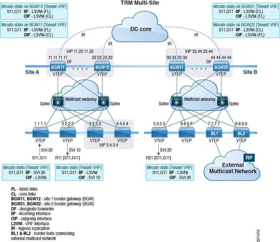
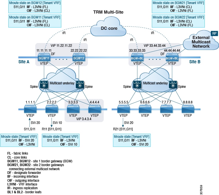
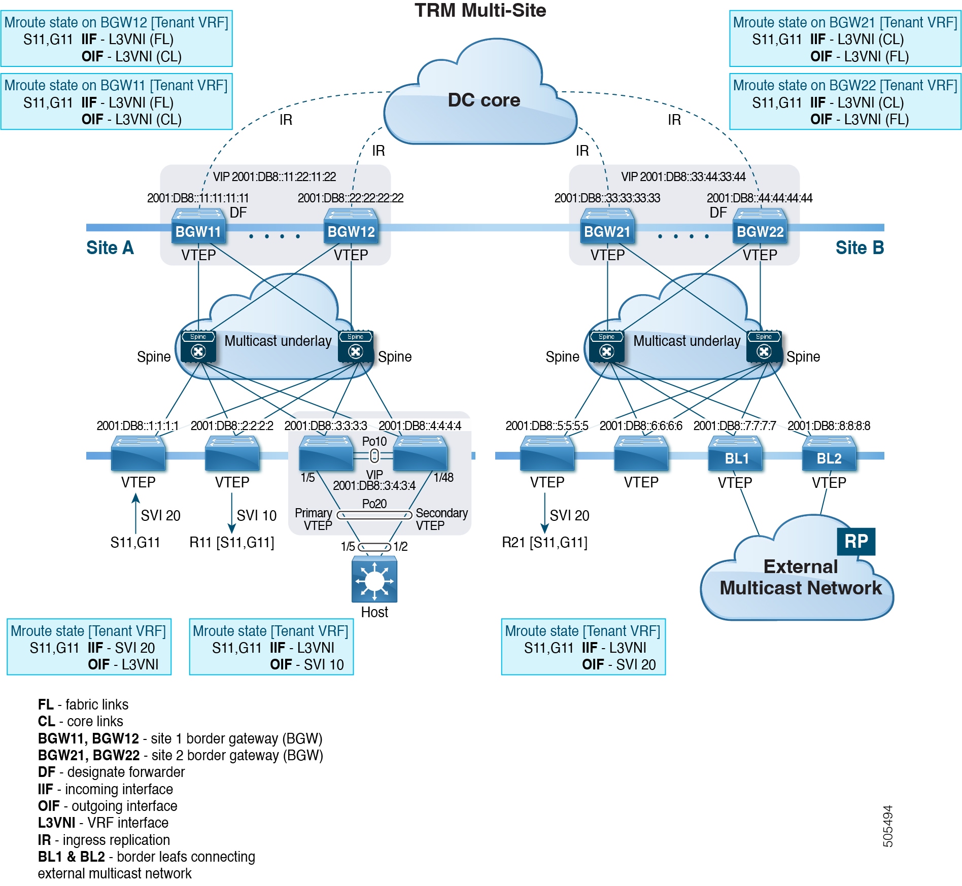
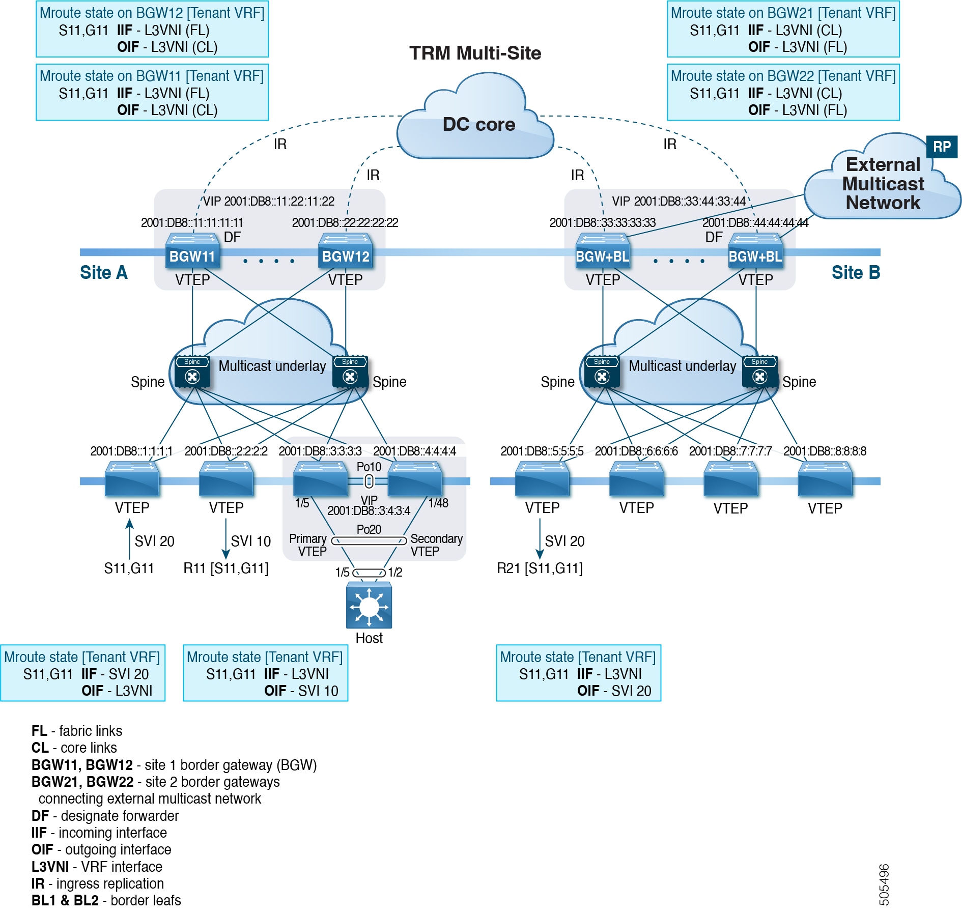
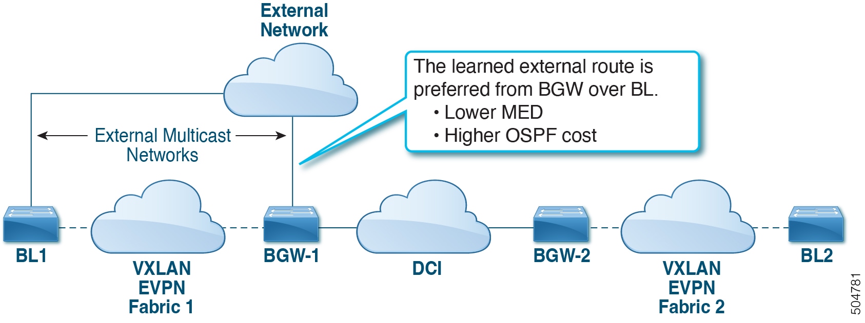
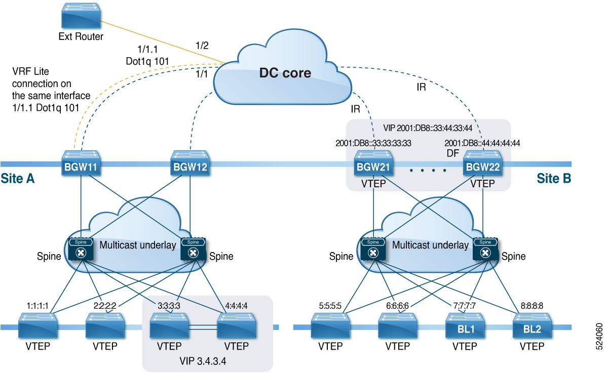
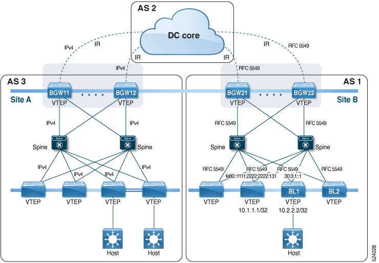
All routes that reach destinations outside a fabric have a next hop on the BGW, for both Layer 2 and Layer 3 traffic. The BGW serves as the node that interacts both with local site nodes and with nodes external to the site. In a leaf-spine data center fabric, BGWs can be leaf switches, spine switches, or dedicated gateway devices.

The VXLAN EVPN multi-site approach creates multiple site-local EVPN control planes and IP forwarding domains, interconnected by a single, common EVPN control and IP forwarding domain.

  • Each EVPN node receives a unique site-scope identifier. Site-local EVPN domains consist of nodes using the same identifier; BGWs belong both to their site’s EVPN domain and to the common multi-site EVPN domain.

  • Site-local bridging, routing, and flood domains connect only via BGWs to corresponding domains in other sites.

  • Selective advertisement on BGWs configures per-tenant information, such as IP VRF or MAC VRF (EVPN instance). When external connectivity (VRF-lite) and EVPN Multi-Site share a BGW, advertisements remain enabled.

  • In the BGP control plane, for releases prior to Cisco NX-OS Release 9.3(5), BGWs rewrite next hop information for EVPN routes and reoriginate them. Beginning with Cisco NX-OS Release 9.3(5), reorigination is always enabled (with either single or dual route distinguishers), and rewrite is not performed. For more information, see .

If a data center has three EVPN overlay domains, each domain is connected to others only through its designated BGWs, which enforce traffic boundaries and provide scalable inter-site forwarding.
Connecting two EVPN overlays directly, without BGWs, bypasses traffic enforcement and failure containment, and does not qualify as a VXLAN EVPN multi-site deployment.
Attribute VXLAN EVPN single-site VXLAN EVPN multi-sites
Scope of control Single overlay domain Multiple overlay domains
Inter-site gateway Not required Required (BGWs)
Failure containment Fabric-wide Site-specific, enforced at BGWs

A VXLAN EVPN multi-site is like several office buildings (sites), each protected by its own security staff (BGWs). Visitors and deliveries travel only through main entrances (BGWs), ensuring each building’s safety and managing interactions between locations.

VXLAN EVPN multi-site deployments with IPv6 underlays

A VXLAN EVPN multi-site deployment with IPv6 underlays is a network architecture solution that

  • extends Layer 2 and Layer 3 connectivity across multiple data center sites using VXLAN and EVPN technologies

  • utilizes IPv6 as the underlay transport protocol with support for multicast (PIMv6) and ingress replication, and

  • enables scalable, resilient inter-site communication through Anycast Border Gateways (BGWs) and flexible

    underlay options.

Beginning with Cisco NX-OS Release 10.4(3)F, the support is provided for VXLAN EVPN Multi-Site with IPv6 Underlay.

  • VXLAN EVPN Multi-Site with IPv6 Underlay enables the use of IPv6 Multicast running PIMv6 in the underlay fabric.

  • RP is positioned in the spine with anycast RP.

  • BGWs support VXLAN with IPv6 Protocol-Independent Multicast (PIMv6) Any-Source Multicast (ASM) on the fabric side and Ingress Replication (IPv6) on the DCI side.

Beginning with Cisco NX-OS Release 10.5(1)F, the underlay network supports the following combinations for VXLAN EVPN Multi-Site:

  • In the data center fabric, both Multicast Underlay (PIMv6) Any-Source Multicast (ASM) and Ingress Replication (IPv6) are supported.

  • In the Data Center Interconnect (DCI), only Ingress Replication (IPv6) is supported.

Figure 1. Topology - VXLAN EVPN Multi-Site with IPv6 Underlay
Topology - VXLAN EVPN Multi-Site with IPv6 Underlay

The topology describes a typical VXLAN EVPN multi-site deployment with IPv6 underlay:

  • Four leaf switches and two spine switches form the core fabric.

  • Two Anycast BGWs connect the sites.

  • IPv6 multicast runs within the fabric, while ingress replication is used on the DCI.

Dual RDs for multi-site

A dual RD is a route distinguishing mechanism that

  • enables the use of both a primary and secondary route distinguisher (RD) in VXLAN EVPN multi-site deployments

  • allows reoriginated routes to be advertised with a secondary type-0 RD (site-id:VNI format), and

  • supports automatic allocation of the secondary RD for border gateways (BGWs).

Beginning with Cisco NX-OS Release 9.3(5), VXLAN EVPN Multi-Site supports route reorigination with RDs. This feature is enabled automatically.

  • Each VRF or L2VNI tracks two RDs:

    • The primary RD is unique to each instance.

    • The secondary RD is the same across BGWs.

  • Reoriginated routes are advertised with the secondary type-0 RD (using a site-id:VNI format).

  • All other routes use the primary RD.

  • The secondary RD is allocated automatically when the router operates in Multi-Site BGW mode.

If the site ID is greater than 2 bytes, the secondary RD can't be generated automatically on the Multi-Site BGW, and the following message appears:

%BGP-4-DUAL_RD_GENERATION_FAILED: bgp- [12564] Unable to generate dual RD on EVPN multisite border gateway. This may increase memory consumption on other BGP routers receiving re-originated EVPN routes. Configure router bgp <asn> ; rd dual id <id> to avoid it.

In this case, you can either manually configure the secondary RD value or disable dual RDs. For more information, see Configure dual RD support for Multi-Site.

RP placements in DCI cores

RP placements in DCI cores are multicast routing design approaches that

  • ensure that PIM Rendezvous Points (RPs) for the Data Center Interconnect (DCI) multicast underlay are distinct from those used in the fabric underlay

  • prevent multicast group overlap between the DCI and fabric networks, and

  • allow flexible selection and redundancy of RP locations to maintain robust multicast operations.

Proper RP placements in DCI cores are critical for scalable and reliable multicast routing across interconnected data centers. Logical separation between multicast domains within the fabric and DCI protects against routing conflicts and unintended traffic propagation.

  • PIM RPs and multicast groups for the fabric underlay and the DCI underlay must be different.

  • The multicast group range used in the DCI underlay must not overlap with the group range used in the fabric underlay.

  • Multicast groups and RPs in DCI and fabric networks should be distinct and configured based on specific address ranges.

  • RPs can be placed on any node in the DCI core; multiple RPs may be used for redundancy.

Direct BGW to BGW Peering Deployment: For direct Border Gateway (BGW) to BGW peering, set up PIM RPs on BGW devices. Use anycast PIM RP for redundancy in case of failure.

BGW to Cloud Model Deployment: In designs involving peering between BGWs and the cloud, place the PIM RP on core routers or superspine switches in the DCI underlay layer.

A deployment where the DCI underlay uses the same multicast group range or shares the same PIM RP as the fabric underlay can cause routing conflicts and disrupt multicast traffic flows.

Supported ESI behavior for EVPN multi-homing and Anycast BGW

Beginning Cisco NX-OS Release 10.2(2)F, EVPN MAC/IP routes (Type 2) with both reserved and non-reserved Ethernet Segment Identifier (ESI) values are evaluated for forwarding (ESI RX). See RFC 7432 Section 9.2.2 for the definition of EVPN MAC/IP route resolution.

  • Type 2 MAC/IP routes with reserved ESI values (0 or MAX-ESI) are resolved solely by the MAC/IP route (BGP next-hop within Type 2).

  • Type 2 MAC/IP routes with non-reserved ESI values are resolved only when an associated per-ES Ethernet Auto-Discovery (EAD) route (Type 1, per-ES EAD) is present.

  • On Multi-Site Anycast Border Gateway (BGW), MAC/IP routes with both reserved and non-reserved ESI values can be forwarded, rewritten, and re-originated. The Multi-Site BGW always re-originates the per-ES EAD route in these cases.

Supported platforms and configuration guidelines for VXLAN EVPN Multi-Site

VXLAN EVPN Multi-Site supports a range of Cisco Nexus platforms, specific line cards, and firmware versions. Configuration guidelines and operational restrictions ensure optimal deployment and feature compatibility.

Supported Cisco Nexus platforms

VXLAN EVPN Multi-Site is supported on the following platforms and line cards:

  • Cisco Nexus 9300-EX and 9300-FX platform switches

  • Cisco Nexus 9300-FX2, 9300-FX3, and 9300-GX platform switches

  • Cisco Nexus 9300-GX2 platform switches

  • Cisco Nexus 9332D-H2R switches

  • Cisco Nexus 93400LD-H1 switches

  • Cisco Nexus 9364C-H1 switches

  • Cisco Nexus 9800 platform switches with X9836DM-A and X98900CD-A line cards

  • Cisco Nexus 9500 platform switches with -EX or -FX or -GX or -FX3 line cards


    Note


    Cisco Nexus 9500 platform switches with -R/RX line cards don't support VXLAN EVPN Multi-Site.


  • Beginning with Cisco NX-OS Release 10.5(2)F, the following features are supported on Cisco Nexus 9500 Series switches with N9K-X9736C-FX3 line card.

    • Multi-Hop BFD

    • VXLAN and iVXLAN stripping

    • DCI advertise PIP (without cloudsec) on vPC and Anycast BGW

Switch or Port restrictions

  • The evpn multisite dci-tracking is mandatory for anycast BGWs and vPC BGW DCI links.

  • EVPN multisite DCI-tracking and EVPN multisite fabric-tracking are only supported on physical interfaces. Use on SVIs is not supported.

Deployment restrictions

  • In a VXLAN EVPN Multi-Site deployment, when you use the ttag feature, make sure that the ttag is stripped ( ttag-strip ) on BGW's DCI interfaces attached to Non-NXOS gear.

  • In TRM with multi-site deployments, all BGWs receive traffic from fabric. However, only the designated forwarder (DF) BGW forwards the traffic. All other BGWs drop the traffic through a default drop ACL. This ACL is programmed in all DCI tracking ports. Don't remove the evpn multisite dci-tracking configuration from the DCI uplink ports. If you do, you remove the ACL, which creates a nondeterministic traffic flow in which packets can be dropped or duplicated instead of deterministically forwarded by only one BGW, the DF.

  • The DCI underlay group and the fabric underlay group must be distinct, ensuring no overlap between DCI multicast and fabric multicast underlay groups.

  • Bind NVE to a loopback address that is separate from loopback addresses that are required by Layer 3 protocols. A best practice is to use a dedicated loopback address for the NVE source interface (PIP VTEP) and multi-site source interface (anycast and virtual IP VTEP).

  • Beginning with Cisco NX-OS Release 9.3(5), if you disable the host-reachability protocol bgp command under the NVE interface in a VXLAN EVPN Multi-Site topology, the NVE interface stays operationally down.

  • Ensure that the ip pim sparse-mode is enabled on the Multi-Site VIP loopback interface.

  • Multi-Site BGW deployment restrictions:

    • The Multi-Site BGW allows the coexistence of Multi-Site extensions (Layer 2 unicast/multicast and Layer 3 unicast) as well as Layer 3 unicast and multicast external connectivity.

    • Beginning with Cisco NX-OS Release 9.3(5), Multi-Site Border Gateways re-originate incoming remote routes when advertising to the site's local spine/leaf switches. These re-originated routes modify the following fields:

      • RD value changes to [Multisite Site ID:L3 VNID].

      • It is mandatory that Route-Targets are defined on all VTEP that are participating in a given VRF, this includes and is explicitly required for the BGW to extend the given VRF. Prior to Cisco NX-OS Release 9.3(5), Route-Targets from intra-site VTEPs were inadvertently kept across the site boundary, even if not defined on the BGW. Starting from Cisco NX-OS Release 9.3(5) the mandatory behavior is enforced. By adding the necessary Route-Targets to the BGW, the change from inadvertent Route-Target advertisement to explicit Route-Target advertisement can be performed.

      • Path type changes from external to local.

      • For SVI-related triggers (such as shut/unshut or PIM enable/disable), a 30-second delay was added, allowing the Multicast FIB (MFIB) Distribution module (MFDM) to clear the hardware table before toggling between L2 and L3 modes or vice versa.

    • In a VXLAN Multi-Site environment, a border gateway device that uses ECMP for routing through both a VXLAN overlay and an L3 prefix to access remote site subnets might encounter adjacency resolution failure for one of these routes. If the switch attempts to use this unresolved prefix, it will result in traffic being dropped.

  • Convergence recommendations

    • To improve the convergence in case of fabric link failure and avoid issues in case of fabric link flapping, ensure to configure multi-hop BFD between loopbacks of spines and BGWs.

      In the specific scenario where a BGW node becomes completely isolated from the fabric due to all its fabric links failing, the use of multi-hop BFD ensures that the BGP sessions between the spines and the isolated BGW can be immediately brought down, without relying on the configured BGP hold-time value.

    • To improve convergence during the reload of anycast BGW routers in multi-plane topology, ensure to configure the multi-hop BFD and nexthop trigger-delay commands.

vPC BGW restrictions

  • BGWs in a vPC topology are supported.

  • vPC mode can support only two BGWs.

  • vPC mode can support both Layer 2 hosts and Layer 3 services on local interfaces.

  • In vPC mode, BUM is replicated to either of the BGWs for traffic coming from the external site. Hence, both BGWs are forwarders for site external to site internal (DCI to fabric) direction.

  • In vPC mode, BUM is replicated to either of the BGWs for traffic coming from the local site leaf for a VLAN using Ingress Replication (IR) underlay. Both BGWs are forwarders for site internal to site external (fabric to DCI) direction for VLANs using the IR underlay.

  • In vPC mode, BUM is replicated to both BGWs for traffic coming from the local site leaf for a VLAN using the multicast underlay. Therefore, a decapper/forwarder election happens, and the decapsulation winner/forwarder only forwards the site-local traffic to external site BGWs for VLANs using the multicast underlay.

  • In vPC mode, all Layer 3 services/attachments are advertised in BGP via EVPN Type-5 routes with their virtual IP as next hop. If the VIP/PIP feature is configured, they are advertised with PIP as the next hop.

Multi-site BGW maintenance mode restrictions

  • BUM Traffic from remote Fabrics will still be attracted to the Border gateway that is in maintenance mode

  • Border Gateway in maintenance mode still participates in Designated Forwarder Election

  • Default Maintenance mode profile applies the command "ip pim isolate" and so the Border gateway is isolated from S,G tree towards the fabric direction. This leads to BUM traffic loss and hence an appropriate maintenance mode profile should be used for Border Gateways than the default.

Unsupported features

  • Multicast Flood Domain between inter-site/fabric BGWs isn't supported.

  • iBGP EVPN Peering between BGWs of different fabrics/sites isn't supported.

  • PIM BiDir is not supported for fabric underlay multicast replication with VXLAN Multi-Site.

  • FEX is not supported on a vPC BGW and Anycast BGW.

Anycast BGW restrictions

  • Anycast mode can support up to six BGWs per site.

  • Anycast mode can support only Layer 3 services that are attached to local interfaces.

  • In Anycast mode, BUM is replicated to each border leaf. DF election between the border leafs for a particular site determines which border leaf forwards the inter-site traffic (fabric to DCI and conversely) for that site.

  • In Anycast mode, all Layer 3 services are advertised in BGP via EVPN Type-5 routes with their physical IP as the next hop.

  • If different Anycast Gateway MAC addresses are configured across sites, enable ARP suppression and ND suppression for all VLANs that have been extended.

Supported features

  • VXLAN EVPN Multi-Site and Tenant Routed Multicast (TRM) are supported between sources and receivers deployed across different sites.

  • Prior to NX-OS 10.2(2)F only ingress replication was supported between DCI peers across the core. Beginning with Cisco NX-OS Release 10.2(2)F both ingress replication and multicast are supported between DCI peers across the core.

  • Beginning with Cisco NX-OS Release 9.3(5), VTEPs support VXLAN-encapsulated traffic over parent interfaces if subinterfaces are configured. This feature is supported for VXLAN EVPN Multi-Site and DCI. DCI tracking can be enabled only on the parent interface.

  • Beginning with Cisco NX-OS Release 9.3(5), VXLAN EVPN Multi-Site supports asymmetric VNIs. For more information, see Multi-Site with Asymmetric VNIs and .

Dual RD support for multi-site

  • Dual RD are supported beginning with Cisco NX-OS Release 9.3(5).

  • Dual RD is enabled automatically for Cisco Nexus 9332C, 9364C, 9300-EX, and 9300-FX/FX2 platform switches and Cisco Nexus 9500 platform switches with - EX/ FX /FX3 line cards that have VXLAN EVPN Multi-Site enabled.

  • Beginning with Cisco NX-OS Release 10.2(3)F, the dual RD support for Multi-Site is supported on the Cisco Nexus 9300-FX3 platform switches.

  • To use CloudSec or other features that require PIP advertisement for multi-site reoriginated routes, configure BGP additional paths on the route server if dual RD are enabled on the BGW, or disable dual RD.

  • Sending secondary RD additional paths at the BGW node isn't supported.

  • During an ISSU, the number of paths for the leaf nodes might double temporarily while all BGWs are being upgraded.

Guidelines and Limitations for VXLAN Multi-Site Anycast BGW Support on Cisco Nexus 9800 Series Switches

  • Beginning with Cisco NX-OS Release 10.4(3)F, the VXLAN Multi-Site Anycast BGW is supported on the Cisco Nexus 9808/9804 switches with X9836DM-A and X98900CD-A line cards.

    • VXLAN Multi-Site Anycast BGW supports the following features:

      • VXLAN BGP EVPN fabric and multi-site interconnect

      • VXLAN Layer-2 VNI and new Layer-3 VNI which is not VLAN based

      • IPv4 and IPv6 underlay

      • Ingress Replication on fabric and DCI side

      • Multicast underlay in Fabric

      • Bud node

      • TRMv4 and TRMv6

      • NGOAM

      • VXLAN Counters

        • Per VXLAN peer based total packet/byte counters are supported.

        • Per VNI based total packet/byte counters are supported

    • VXLAN Multi-Site Anycast BGW does not support the following features:

      • Downstream VNI and route leak

      • L3 Port channel as a fabric or DCI link

      • Multicast underlay on DCI side

      • VXLAN access features

      • IGMP snooping

      • Separate VXLAN counters for broadcast, multicast, and unicast traffic

      • Data MDT

      • EVPN storm control

Best practice for VXLAN EVPN Multi-Site with IPv6 Underlay

Follow these best practices and adhere to these configuration limitations for deploying VXLAN EVPN Multi-Site with IPv6 Underlay:

  • Deploy Cisco Nexus 9300-FX, FX2, FX3, GX, GX2, H2R, and H1 ToR switches as leaf VTEPs or BGWs.

  • Use Cisco Nexus N9K-X9716D-GX and N9K-X9736C-FX, N9K-X9736C-FX3 line cards exclusively as spines (EoR).

  • When deploying an EoR as a spine node with Multicast Underlay (PIMv6) Any-Source Multicast (ASM), always configure a non-default template using one of the following global configuration mode commands:

    • system routing template-multicast-heavy

    • system routing template-multicast-ext-heavy

  • Do not configure vPC BGWs with IPv6 multicast underlay.

  • Do not use dual stack configuration for NVE source interface loopback and multi-site interface loopback; IPv6-only is supported.

  • Beginning with Cisco NX-OS Release 10.5(1)F, you can deploy VXLAN EVPN Multi-Site with both Multicast Underlay (PIMv6) ASM and Ingress Replication (IPv6) in the underlay.

    • Deploy Cisco Nexus 9300-FX, FX2, FX3, GX, GX2, H2R, and H1 ToR switches as the leaf VTEPs.

    • Configure Cisco Nexus N9K-X9716D-GX and N9K-X9736C-FX line cards as spines if the underlay is configured for Multicast Underlay (PIMv6) Any-Source Multicast (ASM).

    • Configure Cisco Nexus N9K-X9716D-GX and N9K-X9736C-FX line cards as VTEPs if the underlay uses Ingress Replication (IPv6).

  • Beginning with Cisco NX-OS Release 10.5(2)F, you can deploy VXLAN EVPN Multi-Site with IPv6 Underlay for Cisco Nexus 9500 Series switches with N9K-X9736C-FX3 line cards as VTEPs if the underlay uses Ingress Replication (IPv6).

Enable VXLAN EVPN Multi-Site

Use this procedure on each Border Gateway (BGW) switch to activate and configure VXLAN EVPN Multi-Site. Ensure the site ID is consistent across all BGWs within a site.

Follow these steps to enable VXLAN EVPN Multi-Site:

Before you begin

Ensure you have administrative privileges.

  • Verify that required software features are licensed and available.

  • Plan your loopback interfaces and IPs for source and BGW VIP.

  • Confirm underlay connectivity and routing advertisement for loopback addresses.

Procedure


Step 1

Enter global configuration mode.

Example:

switch# configure terminal

Step 2

Enable EVPN Multi-Site and configure the site ID. evpn multisite border-gateway ms-id

Example:

switch(config)# evpn multisite border-gateway 100 

The range of values for ms-id is 1 to 2,814,749,767,110,655. Ensure the same site ID is configured on all BGWs in the fabric.

Step 3

(Optional) Enable split-horizon per-site if using DCI multicast underlay with anycast BGW.

Example:

switch(config-evpn-msite-bgw)# split-horizon per-site 

Note


Use this command when DCI multicast underlay is configured on a site with anycast border gateway.

Step 4

Create the NVE (Network Virtualization Edge) interface.

Example:

switch(config-evpn-msite-bgw)# interface nve 1

Note


Only one NVE interface is allowed on the switch.

Step 5

Assign the source interface as a loopback with a /32 IP address advertised throughout the transport network.

Example:

switch(config-if-nve)# source-interface loopback 0 

The source interface must be a loopback interface that is configured on the switch with a valid /32 IP address. This /32 IP address must be known by the transient devices in the transport network and the remote VTEPs. This requirement is accomplished by advertising it through a dynamic routing protocol in the transport network.

Step 6

Configure BGP as the host-reachability protocol for VXLAN Ethernet VPN. host-reachability protocol bgp

Example:

switch(config-if-nve)# host-reachability protocol bgp

Step 7

Specify the multisite border-gateway interface (another loopback, different from the source interface) for the BGW Virtual IP.

Example:

switch(config-if-nve)# multisite border-gateway interface loopback 100

Defines the loopback interface used for the BGW virtual IP address (VIP). The border-gateway interface must be a loopback interface that is configured on the switch with a valid /32 IP address. This /32 IP address must be known by the transient devices in the transport network and the remote VTEPs. This requirement is accomplished by advertising it through a dynamic routing protocol in the transport network. This loopback must be different than the source interface loopback. The range of vi-num is from 0 to 1023.

Step 8

Activate the NVE interface.

Example:

switch(config-if-nve)# no shutdown
switch(config-if-nve)# exit
switch(config-if)# exit
switch(config

Step 9

Configure and loopback interfaces and IP addresses.

Example:

switch(config)# interface loopback 0 
switch(config-if)# ip address 192.0.2.0/32 

VXLAN EVPN Multi-Site is enabled on the BGW switch. The device is ready to participate in multi-site fabric connectivity.

Enable VXLAN EVPN Multi-Site with IPv6 multicast underlay

Enable VXLAN EVPN Multi-Site with an IPv6 multicast underlay on border gateway switches (BGWs).

Apply this configuration only on the BGWs. Ensure all BGWs in the fabric/site use the same site ID and correctly configured loopback interfaces with /128 IPv6 addresses.

Follow these steps to enable VXLAN EVPN Multi-Site with an IPv6 multicast underlay:

Before you begin

  • Verify that required loopback interfaces are configured and reachable.

  • Confirm IPv6 multicast routing and BGP are enabled on your network.

Procedure


Step 1

Enter global configuration mode.

Example:

switch# configure terminal

Step 2

Set the Multi-Site border gateway site ID (use the same ms-id on all BGWs in the site).

Example:

switch(config)# evpn multisite border-gateway 100 

The range of values for ms-id is 1 to 2,814,749,767,110,655. The ms-id must be the same in all BGWs within the same fabric/site.

Note


The mvpn vri id id command is required on BGWs if site-id value is greater than 2 bytes, and this value has to be same across all same site BGWs and unique in TRM domain. Also this value must not collide with any site-id value.

Step 3

Enter NVE interface configuration and specify the source interface as the configured loopback with a /128 IPv6 address.

Example:

switch(config-evpn-msite-bgw)# interface nve 1
switch(config-if-nve)# source-interface loopback 0 

Note


Only one NVE interface is allowed on the switch.

The source interface must be a loopback interface that is configured on the switch with a valid /128 IPv6 address. This /128 IPv6 address must be known by the transient devices in the transport network and the remote VTEPs. This requirement is accomplished by advertising it through a dynamic routing protocol in the transport network.

Step 4

Set BGP as the host-reachability protocol.

Example:

switch(config-if-nve)# host-reachability protocol bgp

Step 5

Assign the loopback interface used as the border-gateway virtual IPv6 address (must be different from the source interface).

Example:

switch(config-if-nve)# multisite border-gateway interface loopback 100

Defines the loopback interface used for the BGW virtual IPv6 address (VIP). The border-gateway interface must be a loopback interface that is configured on the switch with a valid /128 IPv6 address. This /128 IPv6 address must be known by the transient devices in the transport network and the remote VTEPs. This requirement is accomplished by advertising it through a dynamic routing protocol in the transport network. This loopback must be different than the source interface loopback. The range of vi-num is from 0 to 1023.

Step 6

(Optional) Manually configure a virtual MAC address for interoperability.

Example:

switch(config-if-nve)# multisite virtual-rmac 0600.0000.abcd

For interoperability with other switches, user have to manually configure vMAC on Nexus 9000 switches to override the auto generated vMAC. The default behavior is to auto generate. If manual VMAC is configured, manual vMAC will take precedence.

Note


Only unicast MAC address range is supported for vMAC address configuration.

Step 7

Configure the VNI(s) and multicast group for the underlay.

Example:

switch(config-if-nve)# member vni 50101
switch(config-if-nve-vni)# multisite ingress-replication
switch(config-if-nve-vni)# mcast-group ff03::101

The range for vni-range is from 1 to 16,777,214. The value of vni-range can be a single value like 5000 or a range like 5001-5008.

Step 8

Enable the NVE interface and exit configuration mode.

Example:

switch(config-if-nve)# no shutdown
switch(config-if-nve)# exit 

Step 9

Configure loopback interfaces with /128 IPv6 addresses as needed for the source and border-gateway interfaces.

Example:

switch(config)# interface loopback 0
switch(config-if)# ipv6 address 2001:DB8::11:11:11:11/128 

The BGW is configured for VXLAN EVPN Multi-Site with an IPv6 multicast underlay.

Configure dual RD support for Multi-Site

Enable and manage dual Route Distinguisher (RD) support for VXLAN EVPN Multi-Site environments.

Follow these steps when you need to manually configure the secondary RD value across Multi-Site border gateways (BGWs) or revert to single RD support.

Before you begin

Before you begin, ensure:

  • VXLAN EVPN Multi-Site is enabled on your device.

  • You have the required BGP Autonomous System Number (AS number).

Procedure


Step 1

Enter global configuration mode.

Example:

switch# configure terminal 
switch(config)#

This command puts the device into global configuration mode.

Step 2

Configure the BGP router process with your autonomous system number.

Example:

switch(config)# router bgp 100 
switch(config-router)#

Use a value from 1 to 4,294,967,295 for autonomous system number.

Step 3

Define the first 2 bytes of the secondary RD for Multi-Site BGWs.

Example:

switch(config-router)# rd dual id 1

Choose a value from 1 to 65535 for rd dual ID. Ensure this ID is consistent across all BGWs in the Multi-Site deployment.

Note

 
To disable dual RD support and revert to a single RD, use the command:
no rd dual

Step 4

(Optional) Verify the secondary RD for a specific Ethernet VPN Instance (EVI).

Example:

switch(config-router)# show bgp evi 100

This command displays the current secondary RD configuration for the specified EVI.


Dual RD support is now configured for Multi-Site, allowing consistent EVPN route identification using both primary and secondary RD values across border gateways.

The following output shows how the secondary RD is displayed:

switch# show bgp evi 100
-----------------------------------------------
  L2VNI ID                     : 100 (L2-100)
  RD                           : 3.3.3.3:32867
  Secondary RD                 : 1:100
  Prefixes (local/total)       : 1/6
  Created                      : Jun 23 22:35:13.368170
  Last Oper Up/Down            : Jun 23 22:35:13.369005 / never
  Enabled                      : Yes
  <ph feature-id="nexus-writer-comment">Associated IP-VRF            : vni101<!--removed as per input from hganapat--></ph>
  Active Export RT list        :
        100:100
  Active Import RT list        :
        100:100

Configure VNI dual mode

This task is used to set up VNI dual mode, allowing BUM traffic to be managed using multicast or ingress replication within and across fabrics/sites.

For more information about configuring multicast or ingress replication for a large number of VNIs, see VXLAN BGP EVPN eBGP topologies.

Follow these steps to configure VNI dual mode:

Before you begin

  • Ensure you have administrator access to the switch CLI.

  • If only a Layer 3 extension is configured on the Border Gateway (BGW), create an additional loopback interface in the same VRF instance on all BGWs and assign a unique IP address per BGW. Redistribute the loopback interface’s IP address into BGP EVPN, especially toward Site-External.

  • For multiple VRFs, if only one is extended to all leaf switches, add a dummy loopback to the extended VRF and advertise through BGP. Otherwise, add dummy loopbacks to each extended VRF and advertise them accordingly.

  • Use the advertise-pip command to prevent potential configuration errors.

Procedure


Step 1

Enter global configuration mode.

Example:

switch# configure terminal

Step 2

Create a VXLAN overlay interface.

Example:

switch(config)# interface nve 1

Note


Only one NVE interface is allowed per switch.

Step 3

Configure the VNI.

Example:

switch(config-if-nve)# member vni 200

The range for vni-range is from 1 to 16,777,214. The value of vni-range can be a single value like 5000 or a range like 5001-5008.

Step 4

Choose one for BUM traffic within the fabric/site

  • Configure the NVE multicast group.
    switch(config-if-nve-vni)# mcast-group 255.0.4.1
  • Enable BGP EVPN with ingress replication.
    switch(config-if-nve-vni)# ingress-replication protocol bgp

Step 5

Defines the Multi-Site BUM replication method for extending the Layer 2 VNI.

Example:

switch(config-if-nve-vni)# multisite ingress-replication

The switch is configured with VNI dual mode, supporting BUM traffic replication via multicast or ingress replication as required for your network fabric/site design.

Configure Fabric/DCI link tracking

Configure tracking for all DCI-facing and site internal/fabric-facing interfaces to control EVPN route origination when links fail.

Tracking ensures EVPN routes are not reoriginated from or to a site if all DCI or fabric links go down. This helps prevent routing issues and is mandatory for Multi-Site EVPN deployments.

Follow these steps to configure Fabric/DCI Link Tracking.

Before you begin

  • Confirm you have administrative access to the device CLI.

  • Identify DCI-facing and site internal/fabric-facing interfaces to be tracked.

Procedure


Step 1

Enter global configuration mode.

Example:

switch# configure terminal

Step 2

Enter interface configuration mode for the DCI or fabric-facing interface.

Example:

switch(config)# interface ethernet1/1

Enters interface configuration mode for the DCI or fabric interface.

Note


Enter one of the following commands in Step 3 or Step 4.

Step 3

Choose one od the required tracking.evpn multisite dci-tracking

Configures DCI interface tracking.

  • To track a DCI-facing interface, enable DCI tracking:
    switch(config-if)# evpn multisite dci-tracking
  • To track a fabric-facing interface (mandatory for anycast BGWs and vPC BGW fabric links), enable fabric tracking:
    switch(config-if)# evpn multisite fabric-tracking

Step 4

Enable the interface.

Example:

switch(config-if)# no shutdown

Fabric/DCI link tracking is enabled. The device will automatically stop reoriginating EVPN routes if all DCI or fabric links at the site go down.

Configure fabric external neighbors

This task is required when you need to establish BGP-based connectivity from your fabric to other sites or external fabrics using Border Gateway nodes. Proper configuration ensures correct route exchange for EVPN across site boundaries

Follow these steps to configure fabric external neighbors:

Before you begin

  • Ensure you have administrative access to the switch.

  • Confirm the AS (Autonomous System) numbers for your site and remote BGP neighbor.

  • Have the IP addresses (IPv4 or IPv6) of the external neighbors ready.

Follow these steps to configure fabric external neighbors.

Procedure


Step 1

Enter global configuration mode.

Example:

switch# configure terminal

Step 2

Configure the local BGP process with your site’s autonomous system number.

Example:

switch(config)# router bgp 100

The range for as-num is from 1 to 4,294,967,295.

Step 3

Configure the BGP neighbor using its IPv4 or IPv6 address.

  • For IPv4:

    switch(config-router)# neighbor 100.0.0.1
  • For IPv6:
    switch(config-router)# neighbor 2001:DB8::100:0:0:1

Step 4

Set the remote autonomous system number for the neighbor.

Example:

switch(config-router-neighbor)# remote-as 69000

Step 5

Designate the peer as a fabric-external type to enable next hop rewrite for Multi-Site deployments.

Example:

switch(config-router-neighbor)# peer-type fabric-external

The default for peer-type is fabric-internal .

Note


The peer-type fabric-external command is required only for VXLAN Multi-Site BGWs. It is not required for pseudo BGWs.

Step 6

Enable the EVPN address family for the neighbor.

Example:

switch(config-router-neighbor)# address-family l2vpn evpn

Step 7

Rewrite the route target autonomous system number for correct EVPN route propagation.

Example:

switch(config-router-neighbor)# rewrite-evpn-rt-asn

Rewrites the route target (RT) information to simplify the MAC-VRF and IP-VRF configuration. BGP receives a route, and as it processes the RT attributes, it checks if the AS value matches the peer AS that is sending that route and replaces it. Specifically, this command changes the incoming route target’s AS number to match the BGP-configured neighbor’s remote AS number. You can see the modified RT value in the receiver router.


Fabric external/DCI neighbors are configured, enabling BGP-based communication and route exchange between your site’s BGWs and external/fabric peers for EVPN services.

Configure VXLAN EVPN Multi-Site storm control

VXLAN EVPN Multi-Site storm control lets you rate-limit BUM traffic, helping prevent network disruptions caused by traffic storms. Storm control is implemented on the ingress direction of fabric and DCI interfaces.


Note


For information on access port storm control, see the Cisco Nexus 9000 Series NX-OS Layer 2 Configuration Guide.


Follow these steps to configure VXLAN EVPN Multi-Site storm control:

Before you begin

  • Remote peer reachability must be only through DCI links. Appropriate routing configuration must ensure that remote site routes are not advertised over Fabric links.

  • Multicast traffic is policed only on DCI interfaces, while unknown unicast and broadcast traffic is policed on both DCI and fabric interfaces.

  • Cisco NX-OS Release 9.3(6) and later releases optimize rate granularity and accuracy. Bandwidth is calculated based on the accumulated DCI uplink bandwidth, and only interfaces tagged with DCI tracking are considered. (Prior releases also include fabric-tagged interfaces.) In addition, granularity is enhanced by supporting two digits after the decimal point. These enhancements apply to the Cisco Nexus 9300-EX, 9300-FX/FX2/FX3, and 9300-GX platform switches.

  • Beginning with Cisco NX-OS Release 10.5(2)F, VXLAN EVPN Multi-Site Storm Control is supported on Cisco Nexus 9500 Series switches with N9K-X9736C-FX3 line card.

Procedure


Step 1

Enter global configuration mode.

Example:

switch# configure terminal 
switch(config)#

Step 2

Configure the storm suppression level for broadcast, multicast, or unknown unicast traffic.

Example:

switch(config)# evpn storm-control unicast level 10 

Example:

switch(config)# evpn storm-control unicast level 10.20 

Configures the storm suppression level as a number from 0–100.

0 means that all traffic is dropped, and 100 means that all traffic is allowed. For any value in between, the unknown unicast traffic rate is restricted to a percentage of available bandwidth. For example, a value of 10 means that the traffic rate is restricted to 10% of the available bandwidth, and anything above that rate is dropped.

Beginning with Cisco NX-OS Release 9.3(6), you can configure the level as a fractional value by adding two digits after the decimal point. For example, you can enter a value of 10.20.


VXLAN EVPN Multi-Site storm control is applied to selected traffic types according to the specified suppression levels. The network drops excess BUM traffic, helping maintain stability and prevent disruption.

EVPN storm control commands for VXLAN Multi-Site environments

You can view the status of EVPN storm control settings in VXLAN Multi-Site environments using theis command:
Command Purpose

slot 1 show hardware vxlan storm-control

Displays the status of EVPN storm control setting.


Note


When the storm control threshold is exceeded, the system logs the following message:

BGWY-1 %ETHPORT-5-STORM_CONTROL_ABOVE_THRESHOLD: Traffic in port Ethernet1/32 exceeds the configured threshold , action - Trap (message repeated 38 times)

Multi-Site with vPC Support

Multi-Site with vPC support

A Multi-Site with vPC support is a network architecture that

  • allows Border Gateways (BGWs) to be part of a vPC complex,

  • supports dually-attached directly-connected hosts (which may be bridged or routed) as well as dually-attached firewalls or other service attachments, and

  • uses vPC-specific multihoming techniques that do not rely on EVPN Type 4 routes for Designated Forwarder (DF) election or split horizon.

In this architecture, vPC BGWs provide flexibility for attaching hosts, firewalls, or service functions to the network through dual connections, enabling both redundancy and load sharing. The reliance on dedicated vPC multihoming techniques increases resiliency and simplifies operations, as it removes the need for certain control-plane mechanisms (such as Type 4 routes).

Guidelines for configuring Multi-Site with vPC support

Follow these guidelines when configuring Multi-Site with vPC support:

  • o not configure 4000 VNIs for vPC, as this is not supported.

  • For BUM traffic with continued VIP use, ensure the MCT link is used as transport during core isolation or fabric isolation, and for unicast traffic in fabric isolation.

  • Beginning with Cisco NX-OS Release 10.1(2), you can use TRM Multisite with vPC BGW.

  • Always prioritize routes to remote Multisite BGW loopback addresses over the DCI link path rather than iBGP protocol with the backup SVI. Use the backup SVI only in the event of a DCI link failure.

  • Do not use vPC BGWs with IPv6 multicast underlay, as this is not supported.

Configure Multi-Site with vPC support

Establish Multi-Site connectivity with vPC support to enable dual-active links and network redundancy across fabrics.

This task is performed when deploying a VXLAN EVPN Multi-Site solution requiring virtual port channel (vPC) integration between border gateways.

Before you begin

  • Ensure devices are running compatible NX-OS software.

  • Verify IP addresses, VLANs, and interface numbers for configuration.

Procedure


Step 1

Enter global configuration mode.

Example:

switch# configure terminal

You are now in configuration mode.

Step 2

Enable core system features: vPC, LACP, interface VLAN, PIM, and OSPF.

Example:

switch(config)# feature vpc
switch(config)# feature lacp
switch(config)# feature interface-vlan
switch(config)# feature pim
switch(config)# feature ospf

Step 3

Define the PIM RP address and multicast group range for the underlay.

Example:

switch(config)# ip pim rp-address 192.0.2.1 group-list 224.0.0/4

Step 4

Configure the vPC domain and peer-keepalive link, including essential vPC parameters.

Example:

switch(config)# vpc domain 1
switch(config-vpc-domain)# peer-switch
switch(config-vpc-domain)# peer-gateway
switch(config-vpc-domain)# peer-keepalive destination 192.0.2.2

There is no default value for vPC domain. The range is from 1 to 1000.

Configures the IPv4 address for the remote end of the vPC peer-keepalive link. The management ports and VRF are the defaults.

Note


The system does not form the vPC peer link until you configure a vPC peer-keepalive link.

Step 5

Enable ARP and IPv6 ND synchronization under the vPC domain.

Example:

switch(config-vpc-domain)# ip arp synchronize
switch(config-vpc-domain)# ipv6 nd synchronize
switch(config-vpc-domain)# delay restore interface-vlan 45  !optional

Enables IP ARP and ND synchronize under the vPC domain to facilitate faster ARP and ND table population following device reload.

The delay restore interface-vlan configuration is optional. We recommend tuning this value when the SVI/VNI scale is high. For example, when the SCI count is 1000, we recommend that you set the delay restore to 45 seconds.

Step 6

Create the vPC peer-link port-channel, add member interfaces, and configure trunking.

Example:

switch(config)# interface port-channel 1
switch(config-if)# switchport
switch(config-if)# switchport mode trunk
switch(config-if)# switchport trunk allowed vlan 1,10,100-200
switch(config-if)# mtu 9216
switch(config-if)# vpc peer-link
switch(config-if)# no shutdown
switch(config)# interface Ethernet1/1, Ethernet1/21
switch(config-if)# channel-group 1 mode active
switch(config-if)# no shutdown

Creates the vPC peer-link port-channel interface and adds two member interfaces to it.

Step 7

Configure infrastructure VLAN and create routed SVI.

Example:

switch(config)# vlan 10
switch(config)# system nve infra-vlans 10
switch(config)# interface vlan 10
switch(config-if)# ip address 10.0.0.1/30
switch(config-if)# ip router ospf process UNDERLAY area 0
switch(config-if)# ip pim sparse-mode
switch(config-if)# no ip redirects
switch(config-if)# mtu 9216
switch(config-if)# no shutdown

Creates the SVI used for the backup routed path over the vPC peer-link.

Step 8

Set up VXLAN NVE interface and EVPN Multi-Site border gateway ID; configure routeable loopbacks for BGP and PIM.

Example:

switch(config)# evpn multisite border-gateway 100
switch(config)# interface nve 1
switch(config-if-nve)# source-interface loopback0
switch(config-if-nve)# host-reachability protocol bgp
switch(config-if-nve)# multisite border-gateway interface loopback100
switch(config-if-nve)# no shutdown
switch(config-if-nve)# exit
switch(config-if)# exit
switch(config)# interface loopback0
switch(config-if)# ip address 198.51.100.0/32
switch(config-if)# ip pim sparse-mode
switch(config-if)# exit
switch(config)# interface loopback100
switch(config-if)# ip address 198.51.100.1/32
switch(config-if)# exit

The range of values for ms-id is 1 to 281474976710655. The ms-id must be the same in all BGWs within the same fabric/site.

Defines the source interface, which must be a loopback interface with a valid /32 IP address. This /32 IP address must be known by the transient devices in the transport network and the remote VTEPs. This requirement is accomplished by advertising the address through a dynamic routing protocol in the transport network.

Defines the loopback interface used for the BGW virtual IP address (VIP). The BGW interface must be a loopback interface that is configured on the switch with a valid /32 IP address. This /32 IP address must be known by the transient devices in the transport network and the remote VTEPs. This requirement is accomplished by advertising the address through a dynamic routing protocol in the transport network. This loopback must be different than the source interface loopback. The range of vi-num is from 0 to 1023.

Step 9

Verify configuration and operational status.

Example:

switch# show vpc brief
switch# show nve peers
switch# show vlan brief
switch# show interface port-channel 1

Confirm that vPC, peer-link, SVI, and NVE interfaces are up and operational.


Multi-Site with vPC support is operational, providing high availability and resilient inter-site connectivity.

Multi-Site vPC support verification commands

These commands provide information to verify Multi-Site with vPC support configuration.

Table 1. vPC Verification Commands

Command

Description

show vpc brief

Displays general vPC and CC status.

show vpc consistency-parameters global

Displays the status of those parameters that must be consistent across all vPC interfaces.

show vpc consistency-parameters vni

Displays configuration information for VNIs under the NVE interface that must be consistent across both vPC peers.

show vpc brief

switch# show vpc brief
Legend:
                (*) - local vPC is down, forwarding via vPC peer-link
 
vPC domain id                     : 1  
Peer status                       : peer adjacency formed ok     (<--- peer up)
vPC keep-alive status             : peer is alive                
Configuration consistency status  : success (<----- CC passed)
Per-vlan consistency status       : success                       (<---- per-VNI CCpassed)
Type-2 consistency status         : success
vPC role                          : secondary                    
Number of vPCs configured         : 1  
Peer Gateway                      : Enabled
Dual-active excluded VLANs        : -
Graceful Consistency Check        : Enabled
Auto-recovery status              : Enabled, timer is off.(timeout = 240s)
Delay-restore status              : Timer is off.(timeout = 30s)
Delay-restore SVI status          : Timer is off.(timeout = 10s)
Operational Layer3 Peer-router    : Disabled
[...]

show vpc consistency-parameters global

switch# show vpc consistency-parameters global
 
    Legend:
        Type 1 : vPC will be suspended in case of mismatch
 
Name                        Type  Local Value            Peer Value            
-------------               ----  ---------------------- -----------------------
[...]
Nve1 Adm St, Src Adm St,    1     Up, Up, 2.1.44.5, CP,  Up, Up, 2.1.44.5, CP,
Sec IP, Host Reach, VMAC          TRUE, Disabled,        TRUE, Disabled,      
Adv, SA,mcast l2, mcast           0.0.0.0, 0.0.0.0,      0.0.0.0, 0.0.0.0,    
l3, IR BGP,MS Adm St, Reo         Disabled, Up,          Disabled, Up,        
                                  198.51.100.1        198.51.100.1
[...]

show vpc consistency-parameters vni

switch(config-if-nve-vni)# show vpc consistency-parameters vni
 
    Legend:
        Type 1 : vPC will be suspended in case of mismatch
 
Name                        Type  Local Value            Peer Value            
-------------               ----  ---------------------- -----------------------
Nve1 Vni, Mcast, Mode,      1     11577, 224.0.0.0,      11577, 224.0.0.0,    
Type, Flags                       Mcast, L2, MS IR       Mcast, L2, MS IR      
Nve1 Vni, Mcast, Mode,      1     11576, 224.0.0.0,      11576, 224.0.0.0,    
Type, Flags                       Mcast, L2, MS IR       Mcast, L2, MS IR
[...]

Asymmetric VNIs in multi-site deployments

Asymmetric VNIs allow you to connect sites with different internal L2VNI and L3VNI assignments to a common MAC VRF or IP VRF by manually aligning route-targets. Use this reference to identify required prerequisites and configuration parameters.

  • Each site uses its own L2VNI and L3VNI values. For example, site 1 uses VNI 200 internally, and site 2 uses VNI 300.

  • Automatic route-target assignment does not match when VNI values differ; a common route-target (such as 222:333) must be manually assigned.


Note


  • Basic multi-site configuration must be completed.

  • VLAN-to-VRF mapping must be configured on each Border Gateway (BGW) to maintain proper L2VNI/L3VNI association and MAC-IP route reorigination.


Site-specific VNI assignments

Site VNIs
Site 1 BGW L2VNI = 200, L3VNI = 201
Site 2 BGW L2VNI = 300, L3VNI = 301

Layer 3 configuration

Assign a common route-target (e.g., 201:301) for VRF context on both BGWs.

Site 1 BGW:

vrf context vni201
  vni 201
  address-family ipv4 unicast
    route-target both auto evpn
    route-target import 201:301 evpn
    route-target export 201:301 evpn

Site 2 BGW:

vrf context vni301
  vni 301
  address-family ipv4 unicast
    route-target both auto evpn
    route-target import 201:301 evpn
    route-target export 201:301 evpn

Layer 2 configuration

  • Assign a common route-target (e.g., 222:333) for L2VNI configuration on both BGWs.

  • Map each L2VNI interface to the corresponding VRF to support MAC-IP route reorigination.

Site 1 BGW:

evpn
  vni 200 l2
    rd auto
    route-target import auto
    route-target import 222:333
    route-target export auto
    route-target export 222:333

Associate the VRF (L3VNI) to the L2VNI for MAC-IP label reorigination:

interface Vlan 200
  vrf member vni201

Site 2 BGW:

evpn
  vni 300 l2
    rd auto
    route-target import auto
    route-target import 222:333
    route-target export auto
    route-target export 222:333

Associate the VRF (L3VNI) to the L2VNI for MAC-IP label reorigination:

interface vlan 300
  vrf member vni301

Result

This configuration enables sites with different VNI assignments to participate in the same MAC VRF or IP VRF and ensures proper route exchange and MAC-IP route stitching across sites.

PIP advertisements

A PIP advertisement is a route distribution method that

  • uses Protocol Independent PIP as the next-hop for EVPN type-5 routes

  • sends routes with the PIP’s RMAC identifier towards the fabric, and

  • replaces VIP-based advertisements with PIP-based forwarding beginning in Cisco NX-OS Release 10.5(1)F

Beginning with Cisco NX-OS Release 10.5(1)F, BGW is configurable to advertise external EVPN type-5 routes using PIP instead of VIP. This feature optimizes route resolution and improves scaling within the fabric.

When BGW advertises an external route via PIP, the next-hop for the EVPN type-5 route is set to the PIP IP address, and the PIP RMAC is used for the MAC address. This allows traffic entering the fabric to be efficiently routed to the BGW using the PIP.

Prior to enabling PIP advertisement, BGW would advertise routes using VIP as the next-hop, which can limit scalability and flexibility compared to PIP advertisements.

PIP advertisement is like giving each route a direct address to its destination, rather than routing everything through a single hub.

Best practice for advertising routes using PIP

Follow these best practices and important precautions when you advertise routes using PIP in Cisco NX-OS environments:

  • Use only Layer 3 support in Cisco NX-OS Release 10.5(1)F.

  • Do not apply this feature on vPC BGW.

  • Anticipate traffic loss until routes are updated on BGW and Leaf after a remote BGW goes down.

  • Configure maximum-paths under EVPN and the VRF’s address-family on the leaf so BGP can select all paths as best-path or multi-paths and download all next-hops to the forwarding plane for load balancing.

  • In topologies with separate BGW and Spine, do one of the following:

    • Disable dual route-distinguisher (RD) on BGWs.

    • If dual RD is enabled on BGWs, configure the add-path command on the Spine to advertise all EVPN paths to Leaf switches.

  • Always configure the fabric-advertise-pip l3 command on all BGWs at the same site.

  • Apply this solution only in multiplane topologies with one BGW per plane per site. If more than one BGW per site is connected to a single plane, this solution is not required.

  • When fabric-advertise-pip l3 is enabled, BGWs accept remote type-5 routes from other BGWs at the same site with their PIP addresses. This increases the number of paths per route on BGWs in proportion to the number of BGWs at the site.

Configure BGW to advertise using PIP towards fabric

Enable Anycast BGW to advertise remote routes with PIP as next-hop towards the fabric.

Follow these steps to configure Configure BGW to advertise using PIP towards fabric:

Before you begin

Before you begin, ensure:

  • You have access to the switch CLI with administrative privileges.

  • You know the multisite ID (ms-id) for your BGWs.

SUMMARY STEPS

  1. Enter global configuration mode.
  2. Configure the EVPN multisite border gateway with your site ID.
  3. Enable advertisement of remote EVPN Type-5 routes with PIP next-hop towards the fabric.
  4. Verify the configuration of the NVE interface and route advertisement.

DETAILED STEPS

  Command or Action Purpose

Step 1

Enter global configuration mode.

Example:

switch# configure terminal

This step enables you to make configuration changes.

Step 2

Configure the EVPN multisite border gateway with your site ID.

Example:

switch(config)# evpn multisite border-gateway 100

Replace 100 with your fabric's site ID (ms-id). The ms-id must be identical for all BGWs in the same fabric/site. The valid range is 1 to 281474976710655.

Step 3

Enable advertisement of remote EVPN Type-5 routes with PIP next-hop towards the fabric.

Example:

switch(config-evpn-msite-bgw)# fabric-advertise-pip l3

This activates route advertisement with PIP as the next-hop across the fabric.

Step 4

Verify the configuration of the NVE interface and route advertisement.

Example:

switch(config)# show nve interface nve 1 detail
Interface: nve1, State: Up, encapsulation: VXLAN
VPC Capability: VPC-VIP-Only [not-notified]
Local Router MAC: 4464.3c31.802f
Host Learning Mode: Control-Plane
Source-Interface: loopback1 (primary: 20:1::21, secondary: 0.0.0.0)
Source Interface State: Up
Virtual RMAC Advertisement: No
NVE Flags:
Interface Handle: 0x49000001
Source Interface hold-down-time: 180
Source Interface hold-up-time: 30
Remaining hold-down time: 0 seconds
Virtual Router MAC: N/A
Virtual Router MAC Re-origination: 0022.3344.5566
Interface state: nve-intf-add-complete
Fabric convergence time: 37 seconds
Fabric convergence time left: 0 seconds
Multisite delay-restore time: 50 seconds
Multisite delay-restore time left: 0 seconds
Multisite dci-advertise-pip configured: False
Multisite fabric-advertise-pip l3 configured: True

The Anycast BGW now advertises remote routes with PIP as the next-hop towards the fabric, ensuring correct route propagation.

TRM with Multi-Site

This section contains these topics:

Tenant routed multicasts with Multi-Site

A Tenant Routed Multicast with Multi-Site deployment is a VXLAN EVPN architecture that

  • enables multicast forwarding across multiple VXLAN EVPN fabrics connected via Multi-Site

  • provides Layer 3 multicast services for multicast sources and receivers across different sites, and

  • addresses the need for efficient East-West multicast traffic between geographically distributed networks.

TRM with Multi-Site Reference Information

  • Each TRM site is operating independently. Border gateways on each site allow stitching across the sites. There can be multiple border gateways for each site.

  • Multicast source and receiver information across sites is propagated by BGP on the border gateways that are configured with TRM. The border gateway on each site receives the multicast packet and re-encapsulates the packet before sending it to the local site. Beginning with Cisco NX-OS Release 10.1(2), TRM with Multi-Site supports both Anycast Border Gateway and vPC Border Gateway.

  • The border gateway that is elected as Designated Forwarder (DF) for the L3VNI forwards the traffic from fabric toward the core side. In the TRM Multicast-Anycast Gateway model, we use the VIP-R based model to send traffic toward remote sites. The IR destination IP is the VIP-R of the remote site. Each site that has the receiver gets only one copy from the source site. DF forwarding is applicable only on Anycast Border Gateways.

TRM with Multi-Site Examples

  • On the remote site, the border gateway that receives inter-site multicast traffic from the core forwards it toward the fabric. DF checks are not performed in the core-to-fabric direction, because non-DF border gateways can also receive a copy for local distribution.

  • Only the Designated Forwarder (DF) sends traffic toward remote sites.

  • Beginning with Cisco NX-OS Release 9.3(3), TRM with Multi-Site supports BGW connections to the external multicast network in addition to the BL connectivity, which is supported in previous releases. Forwarding occurs as documented in the previous example, except the exit point to the external multicast network can optionally be provided through the BGW.

Figure 2. TRM with Multi-Site Topology, BL External Multicast Connectivity
Figure 3. TRM with Multi-Site Topology, BGW External Multicast Connectivity

TRM multi-site architectures with IPv6 underlay

A TRM multi-site architecture with IPv6 underlay is a data center fabric design that

  • uses a VXLAN EVPN fabric composed of multiple leaf and spine switches

  • enables Anycast Border Gateway (BGW) functionality over an IPv6 multicast underlay using PIMv6, and

  • places Rendezvous Points (RPs) in the spine layer with Anycast RP for scalable multicast support, allowing VXLAN with IPv6 PIMv6 on the fabric side and ingress replication for Data Center Interconnect (DCI).

Beginning with Cisco NX-OS Release 10.4(3)F, the support is provided for TRM Multi-Site with IPv6 Underlay.

  • VXLAN EVPN fabric with four leafs and two spines

  • Two Anycast BGWs, underlay is IPv6 Multicast running PIMv6

  • RP positioned in the spine with anycast RP; BGWs support VXLAN with IPv6 PIMv6 ASM on the fabric side and Ingress Replication (IPv6) on the DCI side

Beginning with Cisco NX-OS Release 10.5(1)F, the underlay network supports the following combinations for TRM Multi-Site:

  • In the data center fabric, both Multicast Underlay (PIMv6) Any-Source Multicast (ASM) and Ingress Replication (IPv6) are supported.

  • In the Data Center Interconnect (DCI), only Ingress Replication (IPv6) is supported.

See the following topologies for TRM Multi-Site with IPv6 Underlay:

  • Typical topology includes four leaf switches and two spines forming the fabric.

  • Two Anycast BGWs operate above an IPv6 multicast underlay running PIMv6.

  • The RP is positioned in the spine layer as an Anycast RP, supporting VXLAN with IPv6 PIMv6 ASM on the fabric and ingress replication (IPv6) over the DCI.

Figure 4. TRM Multi-Site with IPv6 Underlay Topology, BL External Multicast Connectivity
Figure 5. TRM Multi-Site with IPv6 Underlay Topology, BGW External Multicast Connectivity

Supported platforms, software versions, and features for TRM with Multi-Site

Tenant Routed Multicast (TRM) with Multi-Site is supported across a range of Cisco Nexus platforms and NX-OS software versions. TRM enables scalable multicast routing between fabric sites in a VXLAN EVPN multi-site environment.

TRM with Multi-SiteSupported platforms

These switches support TRM with Multi-Site:

  • The following platforms support TRM with Multi-Site:

    • Cisco Nexus 9300-EX platform switches

    • Cisco Nexus 9300-FX/FX2/FX3 platform switches

    • Cisco Nexus 9300-GX platform switches

    • Cisco Nexus 9300-GX2 platform switches

    • Cisco Nexus 9332D-H2R switches

    • Cisco Nexus 93400LD-H1 switches

    • Cisco Nexus 9364C-H1 switches

    • Cisco Nexus 9500 platform switches with -EX/ FX /FX3 line cards

TRM multi-site with vPC BGW and with Anycast BGW support

Release

Platforms

9.x

Cisco Nexus 9300 -EX, FX, FX2, and FX3 family switches

10.2(1)F

Cisco Nexus 9300-GX family switches.

10.2(1q)F

N9K-C9332D-GX2B switches

10.4(1)F

Cisco Nexus 9332D-H2R switches.

10.4(2)F

Cisco Nexus 93400LD-H1 switches.

10.5(2)F

Cisco Nexus 9500 Series switches with N9K-X9736C-FX3 line card

Deployment restrictions

  • Beginning with Cisco NX-OS Release 9.3(3), a border leaf and Multi-Site border gateway can coexist on the same node for multicast traffic.

  • Beginning with Cisco NX-OS Release 9.3(3), all border gateways for a given site must run the same Cisco NX-OS 9.3(x) image.

  • Cisco NX-OS Release 10.1(2) has the following guidelines and limitations:

    • Backup SVI is needed between the two vPC peers.

    • Orphan ports attached with L2 and L3 are supported with vPC BGW.

    • TRM multi-site with vPC BGW is not supported with vMCT.

    For details on TRM and Configuring TRM with vPC Support, see Configuring Tenant Routed Multicast.

  • Beginning with Cisco NX-OS Release 10.2(2)F, multicast group configuration is used to encapsulate TRM and L2 BUM packets in the DCI core using the multisite mcast-group dci-core-group command.

Supported features

  • TRM with Multi-Site supports these features:

    • TRM Multi-Site with vPC Border Gateway.

    • PIM ASM multicast underlay in the VXLAN fabric

    • TRM with Multi-Site Layer 3 mode only

    • TRM with Multi-Site with Anycast Gateway

    • Terminating VRF-lite at the border leaf

    • The following RP models with TRM Multi-Site:

      • External RP

      • RP Everywhere

      • Internal RP

  • Prior to NX-OS 10.2(2)F only ingress replication was supported between DCI peers across the core. Beginning with Cisco NX-OS Release 10.2(2)F both ingress replication and multicast are supported between DCI peers across the core.

Feature limitation

  • Border routers reoriginate MVPN routes from fabric to core and from core to fabric.

  • Only one pair of vPC BGW can be configured on one site.

  • A pair of vPC BGW and Anycast BGW cannot co-exist on the same site.

  • Only eBGP peering between border gateways of different sites is supported.

  • Each site must have a local RP for the TRM underlay.

  • Keep each site's underlay unicast routing isolated from another site's underlay unicast routing. This requirement also applies to Multi-Site.

  • MVPN address family must be enabled between BGWs.

  • MED is supported for iBGP only.

VRF-lite hand-off and Multi-site configuration support

  • When configuring BGW connections to the external multicast fabric, be aware of the following:

    • The multicast underlay must be configured between all BGWs on the fabric side even if the site doesn’t have any leafs in the fabric site.

    • Sources and receivers that are Layer-3 attached through VRF-Lite links to the BGW of a single site acting therefore also as Border Leaf (BL) node need to have reachability through the external Layer-3 network. If there's a Layer-3 attached source on BGW BL Node-1 and a Layer-3 attached receiver on BGW BL Node-2 for the same site, the traffic between these two endpoints flows through the external Layer-3 network and not through the fabric.

    • External multicast networks should be connected only through the BGW or BL. If a deployment requires external multicast network connectivity from both the BGW and BL at the same site, make sure that external routes that are learned from the BGW are preferred over the BL. To do so, the BGW must have a lower MED and a higher OSPF cost (on the external links) than the BL.

      The following figure shows a site with external network connectivity through BGW-BLs and an internal leaf (BL1). The path to the external source should be through BGW-1 (rather than through BL1) to avoid duplication on the remote site receiver.

  • The BGW supports VRF-lite hand-off and Multi-site configuration on the same physical interface as shown in the diagram.

Guidelines for configuring TRM Multi-Site with IPv6 underlay

Follow these guidelines when configuring TRM Multi-Site with an IPv6 underlay:

  • Use Cisco Nexus 9300-FX, FX2, FX3, GX, GX2, H2R, and H1 ToR switches as leaf VTEPs in TRM Multi-Site deployments with IPv6 underlay.

  • Use Cisco Nexus N9K-X9716D-GX and N9K-X9736C-FX, N9K-X9736C-FX3 line cards as spine (EoR) in these deployments.

  • Ensure BGWs support VXLAN with Protocol-Independent Multicast (PIMv6) Any-Source Multicast (ASM) on the fabric side and Ingress Replication (IPv6) on the DCI side.

  • If you deploy an EoR as a spine node with Multicast Underlay (PIMv6) Any-Source Multicast (ASM), configure a non-default template using one of the following global configuration commands:

    • system routing template-multicast-heavy

    • system routing template-multicast-ext-heavy

  • Beginning with Cisco NX-OS Release 10.5(1)F, TRM Multi-Site in the data center fabric supports both Multicast Underlay (PIMv6) Any-Source Multicast (ASM) and Ingress Replication (IPv6) in the underlay. This support is available on the following switches and line cards:

    • Cisco Nexus 9300-FX, FX2, FX3, GX, GX2, H2R, and H1 ToR switches as the leaf VTEPs.

    • Cisco Nexus N9K-X9716D-GX and N9K-X9736C-FX line cards as spines if the underlay is configured for Multicast Underlay (PIMv6) Any-Source Multicast (ASM).

    • Cisco Nexus N9K-X9716D-GX and N9K-X9736C-FX line cards as VTEPs if the underlay uses Ingress Replication (IPv6).

  • Beginning with Cisco NX-OS Release 10.5(2)F, TRM Multi-Site with IPv6 Underlay support is extended on Cisco Nexus 9500 Series switches with N9K-X9736C-FX3 line cards as VTEPs if the underlay uses Ingress Replication (IPv6).

Configure TRM with Multi-Site

Use this procedure to configure a switch for VXLAN Multi-Site deployments with TRM, ensuring seamless communication across sites.

Follow these steps to configure TRM with Multi-Site:

Before you begin

The following must be configured:

  • Ensure VXLAN TRM and VXLAN Multi-Site features are enabled on the switch.

  • For Anycast Border Gateway (BGW), follow this procedure. For vPC BGW, ensure vPC is also configured.

Procedure


Step 1

Enter global configuration mode.

Example:

switch# configure terminal

Step 2

Access and enable the NVE interface.

Example:

switch(config)# interface nve1
switch(config-if-nve)# no shutdown

Step 3

Set BGP as the host reachability protocol.

Example:

switch(config-if-nve)# host-reachability protocol bgp

Step 4

Specify loopback interfaces for source and border-gateway.

Example:

switch(config-if-nve)# source-interface loopback 0
switch(config-if-nve)# multisite border-gateway interface loopback 1

Defines the source interface, which must be a loopback interface with a valid /32 IP address. This /32 IP address must be known by the transient devices in the transport network and the remote VTEPs. This requirement is accomplished by advertising the address through a dynamic routing protocol in the transport network.

Defines the loopback interface used for the border gateway virtual IP address (VIP). The border-gateway interface must be a loopback interface that is configured on the switch with a valid /32 IP address. This /32 IP address must be known by the transient devices in the transport network and the remote VTEPs. This requirement is accomplished by advertising the address through a dynamic routing protocol in the transport network. This loopback must be different than the source interface loopback. The range of vi-num is from 0 to 1023.

Step 5

Add a virtual network identifier (VNI) and associate it with a VRF.

Example:

switch(config-if-nve)# member vni 10010 associate-vrf

The range for vni-range is from 1 to 16,777,214 The value of vni-range can be a single value like 5000 or a range like 5001-5008.

Step 6

Configure the multicast group address for the NVE.

Example:

switch(config-if-nve-vni)# mcast-group 224.0.0.0

Step 7

Configure the multicast group for the Data Center Interconnect (DCI) core to encapsulate TRM and L2 BUM packets.

Example:

switch(config-if-nve-vni)# multisite mcast-group 224.1.1.1

Step 8

multisite ingress-replication optimized

Example:

switch(config-if-nve-vni)# multisite ingress-replication optimized

Defines the Multi-Site BUM replication method for extending the Layer 2 VNI.

Step 9

Exit configuration mode and save the configuration.

Example:

switch(config-if-nve-vni)# exit
switch# copy running-config startup-config

TRM with VXLAN Multi-Site is now configured on the switch. BGP is used for host reachability, and the correct multicast settings support inter-site communication.

Configure TRM Multi-Site with IPv6 Underlay

Configure Anycast Border Gateway (BGW) for TRM Multi-Site with an IPv6 multicast underlay, using Protocol-Independent Multicast (PIMv6) Any-Source Multicast (ASM) on the fabric side and optimized Ingress Replication for IPv6 on the Data Center Interconnect (DCI) side.

Follow these steps to configure TRM Multi-Site with IPv6 underlay:

Before you begin

Ensure the following components are configured:

  • VXLAN TRM

  • VXLAN Multi-Site

Procedure


Step 1

Enter global configuration mode.

Example:

switch# configure terminal

Step 2

Configure and enable the NVE interface. interface nve1

Example:

switch(config)# interface nve1
switch(config-if-nve)# no shutdown

Step 3

Set BGP as the protocol for host reachability advertisement.

Example:

switch(config-if-nve)# host-reachability protocol bgp

Step 4

Specify a source interface loopback with a valid /128 IPv6 address.

Example:

switch(config-if-nve)# source-interface loopback 0

Defines the source interface, which must be a loopback interface with a valid /128 IPv6 address. This /128 IPv6 address must be known by the transient devices in the transport network and the remote VTEPs. This requirement is accomplished by advertising the address through a dynamic routing protocol in the transport network.

Step 5

Define a separate loopback interface for the border gateway virtual IP address (VIP).

Example:

switch(config-if-nve)# multisite border-gateway interface loopback 1

Defines the loopback interface used for the border gateway virtual IP address (VIP). The border-gateway interface must be a loopback interface that is configured on the switch with a valid /128 IPv6 address. This /128 IPv6 address must be known by the transient devices in the transport network and the remote VTEPs. This requirement is accomplished by advertising the address through a dynamic routing protocol in the transport network. This loopback must be different than the source interface loopback. The range of vi-num is from 0 to 1023.

Step 6

Configure one or a range of Virtual Network Identifiers (VNIs) and associate a VRF as needed.

Example:

switch(config-if-nve)# member vni 90001 associate-vrf

The range for vni-range is from 1 to 16,777,214. The value of vni-range can be a single value like 5000 or a range like 5001-5008.

Step 7

Set the multicast group IPv6 address for the NVE interface.

Example:

switch(config-if-nve-vni)# mcast-group 2001:DB8::/32

This configures the IPv6 prefix for multicast replication in the fabric.

Step 8

Enable optimized ingress replication for VXLAN Multi-Site.

Example:

switch(config-if-nve-vni)# multisite ingress-replication optimized

This defines the replication method for efficient TRM functionality across sites.


TRM Multi-Site with IPv6 multicast underlay is configured and ready for use, enabling PIMv6 ASM multicast forwarding in the fabric and optimized ingress replication across the DCI.

TRM status in multi-site configurations

To display the status for the TRM with Multi-Site configuration, enter the following command.

Table 2. Command Purpose Lookup

Command

Purpose

show nve vni virtual-network-identifier

Displays the L3VNI.

Note


For this feature, optimized IR is the default setting for the Multi-Site extended L3VNI. The MS-IR flag inherently means that it's MS-IR optimized.

The show nve vni command provides information about the status of TRM (Tenant Routed Multisite) in a multi-site configuration. This reference outlines the command usage, its purpose, and example outputs for both IPv4 and IPv6 environments.

  • For IPv4
    switch(config)# show nve vni 51001
    Codes: CP - Control Plane        DP - Data Plane
           UC - Unconfigured         SA - Suppress ARP
           SU - Suppress Unknown Unicast
           Xconn - Crossconnect
           MS-IR - Multisite Ingress Replication
     
    Interface VNI      Multicast-group   State Mode Type [BD/VRF]      Flags
    --------- -------- ----------------- ----- ---- ------------------ -----
    nve1      51001    226.0.0.1         Up    CP   L3 [cust_1]        MS-IR
  • For IPv6
    switch(config)# show nve vni 90001
    Codes: CP - Control Plane        DP - Data Plane
           UC - Unconfigured         SA - Suppress ARP
           S-ND - Suppress ND
           SU - Suppress Unknown Unicast
           Xconn - Crossconnect
           MS-IR - Multisite Ingress Replication
           HYB - Hybrid IRB mode
    
    Interface VNI      Multicast-group   State Mode Type [BD/VRF]      Flags
    --------- -------- ----------------- ----- ---- ------------------ -----
    nve1      90001    ff03:ff03::101:1  Up    CP   L3 [v1]            MS-IR
    
    switch(config)# 
    • For the Multi-Site configuration, optimized Ingress Replication (IR) is enabled by default for the extended L3VNI.

    • The MS-IR flag in the command output confirms the use of Multisite Ingress Replication optimization.

VXLAN EVPN Multi-Site with RFC 5549 Underlay

VXLAN EVPN multi-site deployments with RFC 5549 underlay

A VXLAN EVPN multi-site deployment with RFC 5549 underlay is a network architecture that

  • uses VXLAN EVPN for scalable Layer 2 and Layer 3 connectivity between geographically separated data centers

  • leverages RFC 5549 to enable IPv4 address advertisement and communication over an IPv6 underlay network, and

  • allows organizations to integrate IPv6 transport seamlessly into existing IPv4 VXLAN EVPN infrastructures.

Additional reference information

RFC 5549 enables the advertisement of underlay IPv4 prefixes using BGP, where the next hop is specified as an IPv6 address. This allows IPv4 connectivity to be established over an IPv6 underlay and supports dual-stack environments.

Example

For example, an enterprise can extend its VXLAN EVPN overlay between multiple campus sites with an IPv6 underlay in place. The enterprise can continue to deliver IPv4-based applications by advertising IPv4 prefixes with BGP and seamlessly integrating both IPv4 and IPv6 transports.

Comparision of Standard VXLAN EVPN with VXLAN EVPN with RFC 5549 underlay

Attribute Standard VXLAN EVPN deployment VXLAN EVPN multi-site deployment with RFC 5549 underlay
Underlay protocol IPv4 IPv6
IPv4 prefix advertisement Via IPv4 next-hop Via IPv6 next-hop (RFC 5549)
IPv6 integration Not required Seamless transition; dual-stack enabled

Benefits of VXLAN EVPN Multi-Site with RFC 5549 Underlay

The following are the benefits of VXLAN EVPN Multi-Site with RFC 5549 Underlay:

  • Helps your network against the exhaustion of IPv4 addresses.

  • Enhances scalability and efficiency by integrating IPv6 into the VXLAN IPv4 network infrastructure.

  • Offers simpler, more direct communication between devices.

  • Provides sub-second convergence.

  • Supports the following topologies:

    • Border spine gateway to leaf.

    • vPC BGWs to leaf.

    • Anycast BGWs to leaf.

Supported platforms and releases for VXLAN EVPN Multi-Site with RFC 5549 underlay

The following platforms and software releases support VXLAN EVPN Multi-Site with RFC 5549 underlay:

Table 3. Supported Platform and Release for VXLAN EVPN Multi-Site with RFC 5549 Underlay

Feature

Release

Platform

VXLAN BGP EVPN with RFC 5549 Underlay on multi-site

10.5(1)F

Cisco Nexus 9000 Series switches

BGP peering options for VXLAN EVPN multi-site with RFC 5549 underlay

VXLAN EVPN multi-site with RFC 5549 underlay supports two types of BGP peering configurations for VTEP IPv4 address advertisement:

  • Link-local address (LLA): In this type of BGP peering configuration, BGP uses the interface's link-local address to establish IPv6 sessions, allowing for the advertisement of IPv4 addresses through them. This approach eliminates the necessity for configuring global addresses on interfaces.

  • Global IPv6 address: In this type of BGP peering configuration, BGP creates a standard IPv6 neighbor relationship using the global IPv6 address of the directly connected interface. Therefore, it is required to configure a global IPv6 address on the directly connected interface for the peering to be established.

Capabilities of VXLAN BGP EVPN with RFC 5549 underlay on multi-site deployments

VXLAN BGP EVPN with RFC 5549 underlay enables scalable and efficient Layer 2/Layer 3 connectivity across multiple sites by supporting IPv6-based underlay routing between network nodes. This solution allows the system to advertise the IPv4 address of the Border Gateway (BGW) VTEP using an IPv6 (link-local or global) next-hop address as required by RFC 5549, enabling seamless site-to-site communication in complex network topologies.

  • Each site’s BGW advertises its VTEP IPv4 address using an IPv6-formatted next-hop, allowing flexible integration between sites that may use different underlay addressing schemes.

  • The RFC 5549 underlay permits the use of IPv6 routing infrastructure for transporting VXLAN traffic, optimizing route distribution and future-proofs the network for IPv6 expansion.

Figure 6. BGW connectivity and address advertisement using RFC 5549

Best practice for VXLAN EVPN Multi-Site with RFC 5549 underlay

Follow these best practices when configuring VXLAN EVPN Multi-Site with an RFC 5549 underlay:

  • Use IPv4 addresses for both the VTEP and VTEP loopback interfaces.

  • Ensure each node is running the recommended NX-OS software version:

    Nodes

    Supported Release

    Core

    10.2(3)F or higher

    Spine

    10.2(3)F or higher

    Leaf

    10.2(3)F or higher

    Border Gateway

    10.5(1)F or higher

    During upgrades, verify that all nodes meet the minimum supported software version requirements.

  • Always prioritize routing to remote multi-site BGW loopback addresses over the DCI link path. Use the backup SVI only if a DCI link failure occurs.

  • Do not configure BGP peering on multiple interfaces with the same link-local address (LLA), as this is not supported and causes unpredictable behavior.

Supported and Unsupported Features of VXLAN EVPN Multi-Site with RFC 5549 Underlay

Following are the supported and unsupported features for VXLAN BGP EVPN with RFC 5549 Underlay on multi-site environment:

Table 4. Supported and Unsupported Features for VXLAN BGP EVPN with RFC 5549 Underlay on Multi-Site

Features

Supported Release

Supported or Not Supported

Ingress Replication

10.5(1)F

Supported

Overlay TCP Session

10.5(1)F

Supported

DSVNI

10.5(1)F

Supported

Anycast BGW

10.5(1)F

Supported

vPC BGW

10.5(1)F

Supported

vMCT

10.5(1)F

Supported

Route Leaking: Host addresses and between non default customer VRFs

10.5(1)F

Supported

IPv4 over RFC 5549 with default VRF

10.5(1)F

Supported

IPv4 over RFC 5549 with tenant VRF

-

Not Supported

Policy Based Routing

-

Not Supported

NGOAM

-

Not Supported

ND Suppression

-

Not Supported

ARP Suppression

-

Not Supported

IPv4 VNF: IPv4 services over IPv4 PE-CE BGP session

-

Not Supported

RFC 5549 VNF: IPv4 services over IPv6 PE-CE BGP session

-

Not Supported

IPv6 VNF: IPv6 services over IPv6 PE-CE BGP session

-

Not Supported

vPC

-

Not Supported

BFD

-

Not Supported

Underlay multicast

-

Not Supported

MultiCast/TRM

-

Not Supported

Firewall Cluster

-

Not Supported

New L3VNI config

-

Not Supported

Group Policy Option

-

Not Supported

First Hop Security

-

Not Supported

PVLAN over VXLAN

-

Not Supported

VXLAN-TE

-

Not Supported

CloudSec

-

Not Supported

Configure VXLAN EVPN Multi-Site with RFC 5549 underlay in a multi-site environment

Use this configuration to allow leaf and spine nodes in a multi-site data center to communicate over VXLAN using IPv6 addresses for underlay transport, supporting both link-local and global addressing.

Follow these steps to configure VXLAN EVPN Multi-Site with RFC 5549 underlay:

Before you begin

  • Have administrator access to all network devices involved.

  • Ensure devices run NX-OS software supporting VXLAN EVPN and RFC 5549.

  • Confirm interface connectivity between BGWs (Border Gateway nodes).

Procedure


Step 1

Enter global configuration mode.

Example:

leaf# config terminal
                        leaf(config)#

Step 2

Configure the main Ethernet interface for the underlay.

Example:

leaf(config)# interface ethernet1/2
                        leaf(config-if)#

Enters Link local interface configuration mode for RFC 5549.

Step 3

Enable IPv4-based lookup for VLANs lacking an IP address.

Example:

leaf(config-if)# ip forward

Step 4

Assign a link-local IPv6 address or select an automation method

  • Manual option
    leaf(config-if)# ipv6 link-local fe80::1111:2222:2222:3101 

    OR

  • Auto option

    leaf(config-if)# ipv6 address use-link-local-only

    OR

  • Auto option

    leaf(config-if)# ipv6 link-local use-bia 

Step 5

(Optional) Configure a global IPv6 address for the interface.

Example:

leaf(config-if)# ipv6 address 2000:1:1::1/64 

Step 6

Exit interface configuration mode.

Example:

leaf(config-if)# exit
                        leaf(config)#

Step 7

Enter BGP router configuration mode.

Example:

leaf(config)# router bgp 1
                        leaf(config-router)#

Step 8

Configure BGP neighbor settings for the interface.

Example:

leaf(config-router)# neighbor ethernet1/2 
                        leaf(config-router)# remote-as 2
                        leaf(config-router-neighbor)# peer-type fabric-external

The default for peer-type is fabric-internal.

Note


The peer-type fabric-external command is required only for VXLAN Multi-Site BGWs.

Step 9

Activate the IPv4 unicast address family and disable peer AS checking as required.

Example:

leaf(config-router-neighbor)# address-family ipv4 unicast
                        leaf(config-router-af)# disable-peer-as-check  ! only needed for eBGP multi-AS topologies

Note


The disable-peer-as-check command is required for eBGP. Configure this parameter on the spine for eBGP when all leafs are using the same AS but the spines have a different AS than leafs. For more information on eBGP configuration, see eBGP Underlay IP Network.


VXLAN EVPN Multi-Site with RFC 5549 underlay is operational. Devices exchange EVPN routes over IPv6-enabled underlay and BGP neighbor sessions are established as required.

VXLAN EVPN multi-site RFC 5549 underlay reference outputs

This topic provides guidance on how to design and interpret VXLAN EVPN multi-site deployments leveraging RFC 5549 for IPv4 over IPv6 transport, illustrated by practical CLI outputs and comparison with traditional approaches.
  • Advertising an IPv4 route over an IPv6 link-local address:

    spine# show ip route 10.1.1.1
    IP Route Table for VRF "default"
    '*' denotes best ucast next-hop
    '**' denotes best mcast next-hop
    '[x/y]' denotes [preference/metric]
    '%<string>' in via output denotes VRF <string>
    
    fe80::1111:2222:2222:131, ubest/mbest: 1/0
        *via 10.1.1.1/32%default, Eth1/2, [200/0], 6d09h, bgp-2, external, tag 2
    
  • Advertising an IPv4 route over a global IPv6 address:

    spine# show ip route 10.2.2.2
    IP Route Table for VRF "default"
    '*' denotes best ucast next-hop
    '**' denotes best mcast next-hop
    '[x/y]' denotes [preference/metric]
    '%<string>' in via output denotes VRF <string>
    
    10.2.2.2/32, ubest/mbest: 1/0
        *via 30:3:1::1%default, Eth1/2, [200/0], 6d09h, bgp-2, external, tag 2
    

In these examples, the IPv4 destination is reachable via an IPv6 next-hop address, as per RFC 5549, enabling border leafs and spines in multi-site VXLAN EVPN architectures to interoperate across IPv6 transport networks.