Configuring the Underlay

This chapter contains these sections:

IP Fabric Underlay

Underlay Considerations

Unicast Underlay:

The primary purpose of the underlay in the VXLAN EVPN fabric is to advertise the reachability of Virtual Tunnel End Points (VTEPs) and BGP peering addresses. The primary criterion for choosing an underlay protocol is fast convergence in the event of node failures. Other criteria are:

  • Simplicity of configuration.

  • Ability to delay the introduction of a node into the network on boot up.

This document details the two primary protocols supported and tested by Cisco, IS-IS and OSPF. It will also illustrate the use of the eBGP protocol as an underlay for the VXLAN EVPN fabric.

For Configuring VXLAN with IPv6 in the Underlay (VXLANv6), see Configure VXLAN with IPv6 in the Underlay (VXLANv6).

Underlay and Overlay Packet Flow and Deployment Considerations

From an underlay/overlay perspective, the packet flow from a server to another over the Virtual Extensible LAN (VXLAN) fabric as mentioned below:

  1. The server sends traffic to the source VXLAN tunnel endpoint (VTEP). The VTEP performs Layer-2 or Layer-3 communication based on the destination MAC and derives the nexthop (destination VTEP).


    Note


    When a packet is bridged, the target end host’s MAC address is stamped in the DMAC field of the inner frame. When a packet is routed, the default gateway’s MAC address is stamped in the DMAC field of the inner frame.


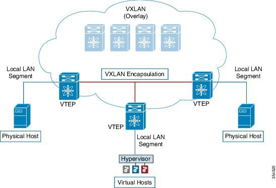
  2. The VTEP encapsulates the traffic (frames) into VXLAN packets (overlay function – see Figure 1) and signals the underlay IP network.

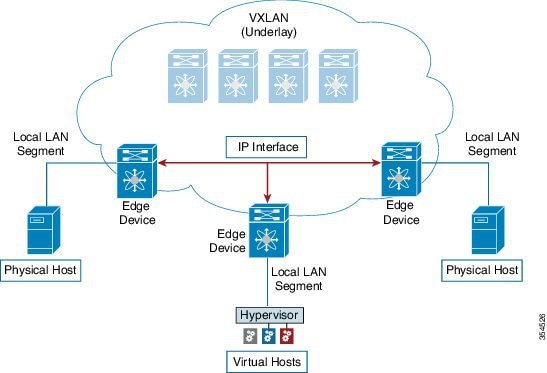
  3. Based on the underlay routing protocol, the packet is sent from the source VTEP to destination VTEP through the IP network (underlay function – see Underlay Overview figure).

  4. The destination VTEP removes the VXLAN encapsulation (overlay function) and sends traffic to the intended server.

The VTEPs are a part of the underlay network as well since VTEPs need to be reachable to each other to send VXLAN encapsulated traffic across the IP underlay network.

The Overlay Overview and Underlay Overview images (below) depict the broad difference between an overlay and underlay. Since the focus is on the VTEPs, the spine switches are only depicted in the background. Note that, in real time, the packet flow from VTEP to VTEP traverses through the spine switches.

Figure 1. Overlay Overview


Figure 2. Underlay Overview


Deployment considerations for an underlay IP network in a VXLAN EVPN Programmable Fabric

The deployment considerations for an underlay IP network in a VXLAN EVPN Programmable Fabric are given below:

  • Maximum transmission unit (MTU) – Due to VXLAN encapsulation, the MTU requirement is larger and we must avoid potential fragmentation.

    • An MTU of 9216 bytes on each interface on the path between the VTEPs accommodates maximum server MTU + VXLAN overhead. Most data center server NICs support up to 9000 bytes. So, no fragmentation is needed for VXLAN traffic.

    • The VXLAN IP fabric underlay supports the IPv4 address family.

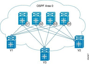
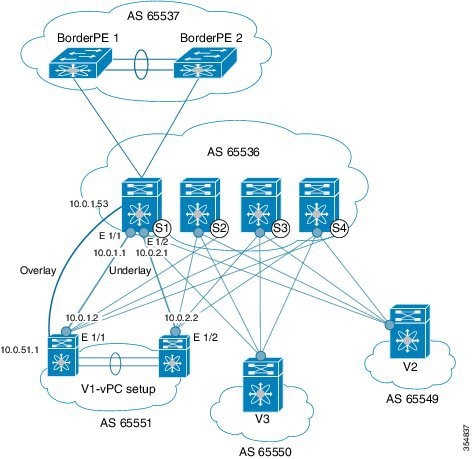
  • Unicast routing - Any unicast routing protocol can be used for the VXLAN IP underlay. You can implement OSPF, IS-IS, or eBGP to route between the VTEPs.


    Note


    As a best practice, use a simple IGP (OSPF or IS-IS) for underlay reachability between VTEPs with iBGP for overlay information exchange.


  • IP addressing – Point-to-point (P2P) or IP unnumbered links. For each point-to-point link, as example between the leaf switch nodes and spine switch nodes, typically a /30 IP mask should be assigned. Optionally a /31 mask or IP unnumbered links can be assigned. The IP unnumbered approach is leaner from an addressing perspective and consumes fewer IP addresses. The IP unnumbered option for the OSPF or IS-IS protocol underlay will minimize the use of IP addresses.

    /31 network - An OSPF or IS-IS point-to-point numbered network is only between two switch (interfaces), and there is no need for a broadcast or network address. So, a /31 network suffices for this network. Neighbors on this network establish adjacency and there is no designated router (DR) for the network.


    Note


    IP Unnumbered for VXLAN underlay is supported starting with Cisco NX-OS Release 7.0(3)I7(2). Only a single unnumbered link between the same devices (for example, spine - leaf) is supported. If multiple physical links are connecting the same leaf and spine, you must use the single L3 port-channel with unnumbered link.


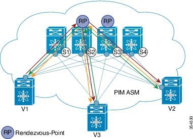
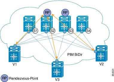
  • Multicast protocol for multi-destination (BUM) traffic – Though VXLAN has the BGP EVPN control plane, the VXLAN fabric still requires a technology for Broadcast/Unknown unicast/Multicast (BUM) traffic to be forwarded.

  • PIM Bidir is supported on Cisco Nexus 9300-EX/FX/FX2 platform switches.

  • Beginning with Cisco NX-OS Release 10.4(3)F, PIM Bidir is also supported on Cisco Nexus 9300-FX3/GX/GX2/H2R/H1 platform switches, and 9500 switches with 9700-GX line cards.

  • Beginning with Cisco NX-OS Release 10.3(5)M, PIM Bidir is also supported on Cisco Nexus 9300-FX3/GX/GX2/H2R/H1 platform switches, and 9500 switches with 9700-GX line cards.

  • Beginning with Cisco NX-OS Release 10.5(2)F, VXLAN PIM Bidir is supported on Cisco Nexus 9500 Series switches with N9K-X9736C-FX3 line card.

  • vPC configuration — This is documented in Configuring vPCs of Cisco Nexus 9000 Series NX-OS Interfaces Configuration Guide.

Unicast routing and IP addressing options

Each unicast routing protocol option (OSPF, IS-IS, and eBGP) and sample configurations are given below. Use an option to suit your setup’s requirements.

  • OSPF

  • IS-IS

  • eBGP

Sample configurations are from an IP underlay perspective and are not comprehensive.

  • For complete configuration information including routing process, authentication, Bidirectional Forwarding Detection (BFD) information, and so on, see Cisco Nexus 9000 Series NX-OS Unicast Routing Configuration Guide.


Important


All routing configuration samples are from an IP underlay perspective and are not comprehensive. For complete configuration information including routing process, authentication, Bidirectional Forwarding Detection (BFD) information, and so on, see Cisco Nexus 9000 Series NX-OS Unicast Routing Configuration Guide.


OSPF Underlay IP Network

Some considerations are given below:

  • For IP addressing, use P2P links. Since only two switches are directly connected, you can avoid a Designated Router/Backup Designated Router (DR/BDR) election.

  • Use the point-to-point network type option. It is ideal for routed interfaces or ports, and is optimal from a Link State Advertisements (LSA) perspective.

  • Do not use the broadcast type network. It is suboptimal from an LSA database perspective (LSA type 1 – Router LSA and LSA type 2 – Network LSA) and necessitates a DR/BDR election, thereby creating an additional election and database overhead.


Note


You can divide OSPF networks into areas when the size of the routing domain contains a high number of routers and/or IP prefixes.. The same general well known OSPF best practice rules in regards of scale and configuration are applicable for the VXLAN underlay too. For example, LSA type 1 and type 2 are never flooded outside of an area. With multiple areas, the size of the OSPF LSA databases can be reduced to optimize CPU and memory consumption.

For ease of use, the configuration mode from which you need to start configuring a task is mentioned at the beginning of each configuration.

  • Configuration tasks and corresponding show command output are displayed for a part of the topology in the image. For example, if the sample configuration is shown for a leaf switch and connected spine switch, the show command output for the configuration displays corresponding configuration.


Note


MTU size of both ends of the link should be configured identically.


OSPF configuration sample – P2P and IP unnumbered network scenarios

Figure 3. OSPF as the underlay routing protocol


OSPF – P2P link scenario with /31 mask

In the above image, the leaf switches (V1, V2, and V3) are at the bottom of the image. They are connected to the 4 spine switches (S1, S2, S3, and S4) that are depicted at the top of the image. For P2P connections between a leaf switch (also having VTEP function) and each spine, leaf switches V1, V2, and V3 should each be connected to each spine switch.

For V1, we should configure a P2P interface to connect to each spine switch.

A sample P2P configuration between a leaf switch (V1) interface and a spine switch (S1) interface is given below:

OSPF global configuration on leaf switch V1

(config) #


				feature ospf
				router ospf UNDERLAY
				router-id 10.1.1.54
			

OSPF leaf switch V1 P2P interface configuration

(config) #


				interface Ethernet 1/41
				description Link to Spine S1
				no switchport
				ip address 198.51.100.1/31
				mtu 9192
				ip router ospf UNDERLAY area 0.0.0.0
				ip ospf network point-to-point
			

The ip ospf network point-to-point command configures the OSPF network as a point-to-point network

The OSPF instance is tagged as UNDERLAY for better recall.

OSPF loopback interface configuration (leaf switch V1)

Configure a loopback interface so that it can be used as the OSPF router ID of leaf switch V1.

(config) #


				interface loopback 0
				ip address 10.1.1.54/32
				ip router ospf UNDERLAY area 0.0.0.0
			

The interface will be associated with the OSPF instance UNDERLAY and OSPF area 0.0.0.0

OSPF global configuration on spine switch S1

(config) #


				feature ospf
				router ospf UNDERLAY
				router-id 10.1.1.53
			

(Corresponding) OSPF spine switch S1 P2P interface configuration

(config) #


				interface Ethernet 1/41
				description Link to VTEP V1
				ip address 198.51.100.2/31
				mtu 9192
				ip router ospf UNDERLAY area 0.0.0.0
				ip ospf network point-to-point
				no shutdown
			

OSPF loopback Interface Configuration (spine switch S1)

Configure a loopback interface so that it can be used as the OSPF router ID of spine switch S1.

(config) #


				interface loopback 0
				ip address 10.1.1.53/32
				ip router ospf UNDERLAY area 0.0.0.0
			

The interface will be associated with the OSPF instance UNDERLAY and OSPF area 0.0.0.0

To complete OSPF topology configuration for the ‘OSPF as the underlay routing protocol’ image, configure the following

  • 3 more V1 interfaces (or 3 more P2P links) to the remaining 3 spine switches.

  • Repeat the procedure to connect P2P links between V2,V3 and V4 and the spine switches.

OSPF - IP unnumbered scenario

A sample OSPF IP unnumbered configuration is given below:

OSPF leaf switch V1 configuration

OSPF global configuration on leaf switch V1

(config) #


					feature ospf
					router ospf UNDERLAY
					router-id 10.1.1.54 
				

The OSPF instance is tagged as UNDERLAY for better recall.

OSPF leaf switch V1 P2P interface configuration

(config) #


					interface Ethernet1/41
					description Link to Spine S1
					mtu 9192
					ip ospf network point-to-point
					ip unnumbered loopback0
					ip router ospf UNDERLAY area 0.0.0.0
				

The ip ospf network point-to-point command configures the OSPF network as a point-to-point network.

OSPF loopback interface configuration

Configure a loopback interface so that it can be used as the OSPF router ID of leaf switch V1.

(config) #


					interface loopback0
					ip address 10.1.1.54/32
					ip router ospf UNDERLAY area 0.0.0.0
				

The interface will be associated with the OSPF instance UNDERLAY and OSPF area 0.0.0.0

OSPF spine switch S1 configuration:

OSPF global configuration on spine switch S1

(config) #


					feature ospf
					router ospf UNDERLAY
					router-id 10.1.1.53
				

(Corresponding) OSPF spine switch S1 P2P interface configuration

(config) #


					interface Ethernet1/41
					description Link to VTEP V1
					mtu 9192
					ip ospf network point-to-point
					ip unnumbered loopback0
					ip router ospf UNDERLAY area 0.0.0.0
				

OSPF loopback interface configuration (spine switch S1)

Configure a loopback interface so that it can be used as the OSPF router ID of spine switch S1.

(config) #


					interface loopback0
					ip address 10.1.1.53/32
					ip router ospf UNDERLAY area 0.0.0.0
				

The interface will be associated with the OSPF instance UNDERLAY and OSPF area 0.0.0.0

To complete OSPF topology configuration for the ‘OSPF as the underlay routing protocol’ image, configure the following:

  • 3 more VTEP V1 interfaces (or 3 more IP unnumbered links) to the remaining 3 spine switches.

  • Repeat the procedure to connect IP unnumbered links between VTEPs V2,V3 and V4 and the spine switches.

OSPF Verification

Use the following commands for verifying OSPF configuration:

Leaf-Switch-V1# show ip ospf
					
					Routing Process UNDERLAY with ID 10.1.1.54 VRF default
					Routing Process Instance Number 1
					Stateful High Availability enabled
					Graceful-restart is configured
					Grace period: 60 state: Inactive 
					Last graceful restart exit status: None
					Supports only single TOS(TOS0) routes
					Supports opaque LSA
					Administrative distance 110
					Reference Bandwidth is 40000 Mbps
					SPF throttling delay time of 200.000 msecs,
					SPF throttling hold time of 1000.000 msecs, 
					SPF throttling maximum wait time of 5000.000 msecs
					LSA throttling start time of 0.000 msecs,
					LSA throttling hold interval of 5000.000 msecs, 
					LSA throttling maximum wait time of 5000.000 msecs
					Minimum LSA arrival 1000.000 msec
					LSA group pacing timer 10 secs
					Maximum paths to destination 8
					Number of external LSAs 0, checksum sum 0
					Number of opaque AS LSAs 0, checksum sum 0
					Number of areas is 1, 1 normal, 0 stub, 0 nssa
					Number of active areas is 1, 1 normal, 0 stub, 0 nssa
					Install discard route for summarized external routes.
					Install discard route for summarized internal routes.
					Area BACKBONE(0.0.0.0) 
					Area has existed for 03:12:54
					Interfaces in this area: 2 Active interfaces: 2
					Passive interfaces: 0  Loopback interfaces: 1
					No authentication available
					SPF calculation has run 5 times
					Last SPF ran for 0.000195s
					Area ranges are
					Number of LSAs: 3, checksum sum 0x196c2
				
Leaf-Switch-V1# show ip ospf interface
				
				loopback0 is up, line protocol is up
				IP address 10.1.1.54/32
				Process ID UNDERLAY VRF default, area 0.0.0.0
				Enabled by interface configuration
				State LOOPBACK, Network type LOOPBACK, cost 1
				Index 1
				Ethernet1/41 is up, line protocol is up
				Unnumbered interface using IP address of loopback0 (10.1.1.54)
				Process ID UNDERLAY VRF default, area 0.0.0.0
				Enabled by interface configuration
				State P2P, Network type P2P, cost 4
				Index 2, Transmit delay 1 sec
				1 Neighbors, flooding to 1, adjacent with 1
				Timer intervals: Hello 10, Dead 40, Wait 40, Retransmit 5
				Hello timer due in 00:00:07
				No authentication
				Number of opaque link LSAs: 0, checksum sum 0
			
Leaf-Switch-V1# show ip ospf neighbors 
				
				OSPF Process ID UNDERLAY VRF default
				Total number of neighbors: 1
				Neighbor ID     Pri State            Up Time  Address         Interface
				10.1.1.53          1 FULL/ -          06:18:32 10.1.1.53        Eth1/41
			

For a detailed list of commands, refer to the Configuration and Command Reference guides.

IS-IS Underlay IP Network

Some considerations are given below:

  • Because IS-IS uses Connectionless Network Service (CLNS) and is independent of the IP, full SPF calculation is avoided when a link changes.

  • Net ID - Each IS-IS instance has an associated network entity title (NET) ID that uniquely identifies the IS-IS instance in the area. The NET ID is comprised of the IS-IS system ID, which uniquely identifies this IS-IS instance in the area, and the area ID. For example, if the NET ID is 49.0001.0010.0100.1074.00, the system ID is 0010.0100.1074 and the area ID is 49.0001.


Important


Level 1 IS-IS in the Fabric —Cisco has validated the use of IS-IS Level 1 only and IS-IS Level 2 only configuration on all nodes in the programmable fabric. The fabric is considered a stub network where every node needs an optimal path to every other node in the fabric. Cisco NX-OS IS-IS implementation scales well to support a number of nodes in a fabric. Hence, there is no anticipation of having to break up the fabric into multiple IS-IS domains.

IS-IS Underlay IP Network Reference Information

Configuration and operational notes for IS-IS underlay deployment:

  • For ease of use, the configuration mode from which you need to start configuring a task is mentioned at the beginning of each configuration.

  • Configuration tasks and corresponding show command output are displayed for a part of the topology in the image. For example, if the sample configuration is shown for a leaf switch and connected spine switch, the show command output for the configuration displays corresponding configuration.

IS-IS configuration sample - P2P and IP unnumbered network scenarios

Figure 4. IS-IS as the underlay routing protocol

In the above image, the leaf switches (V1, V2, and V3, having the VTEP function) are at the bottom of the image. They are connected to the 4 spine switches (S1, S2, S3, and S4) that are depicted at the top of the image.

IS-IS – P2P link scenario with /31 mask

A sample P2P configuration between V1 and spine switch S1 is given below:

For P2P connections between a leaf switch and each spine switch, V1, V2, and V3 should each be connected to each spine switch.

For V1, we must configure a loopback interface and a P2P interface configuration to connect to S1. A sample P2P configuration between a leaf switch (V1) interface and a spine switch (S1) interface is given below:

IS-IS configuration on leaf switch V1

IS-IS global configuration

(config) #


        feature isis
        router isis UNDERLAY
        net 49.0001.0010.0100.1074.00
        is-type level-1
        set-overload-bit on-startup 60


Setting the overload bit - You can configure a Cisco Nexus switch to signal other devices not to use the switch as an intermediate hop in their shortest path first (SPF) calculations. You can optionally configure the overload bit temporarily on startup. In the above example, the set-overload-bit command is used to set the overload bit on startup to 60 seconds.

IS-IS P2P interface configuration (leaf switch V1)

(config) #


        interface Ethernet 1/41
        description Link to Spine S1
        mtu 9192
        ip address 209.165.201.1/31
        ip router isis UNDERLAY


IS-IS loopback interface configuration (leaf switch V1)

Configure a loopback interface so that it can be used as the IS-IS router ID of leaf switch V1.

(config) #


        interface loopback 0
        ip address 10.1.1.74/32
        ip router isis UNDERLAY
      

The IS-IS instance is tagged as UNDERLAY for better recall.

(Corresponding) IS-IS spine switch S1 configuration

IS-IS global configuration

(config) #


        feature isis
        router isis UNDERLAY
        net 49.0001.0010.0100.1053.00
        is-type level-1
        set-overload-bit on-startup 60
      

IS-IS P2P interface configuration (spine switch S1)

(config) #


        interface Ethernet 1/1
        description Link to VTEP V1
        ip address 209.165.201.2/31
        mtu 9192
        ip router isis UNDERLAY
      

IS-IS loopback interface configuration (spine switch S1)

(config) #


        interface loopback 0
        ip address 10.1.1.53/32
        ip router isis UNDERLAY       
        .
        .
      

To complete IS-IS topology configuration for the above image, configure the following:

  • 3 more leaf switch V1’s interfaces (or 3 more P2P links) to the remaining 3 spine switches.

  • Repeat the procedure to connect P2P links between leaf switches V2, V3 and V4 and the spine switches.

IS-IS - IP unnumbered scenario

IS-IS configuration on leaf switch V1

IS-IS global configuration

(config)#


        feature isis
        router isis UNDERLAY
        net 49.0001.0010.0100.1074.00
        is-type level-1
        set-overload-bit on-startup 60
      

IS-IS interface configuration (leaf switch V1)

(config) #


        interface Ethernet1/41
        description Link to Spine S1
        mtu 9192
        medium p2p
        ip unnumbered loopback0
        ip router isis UNDERLAY
      

IS-IS loopback interface configuration (leaf switch V1)

(config)


        interface loopback0
        ip address 10.1.1.74/32
        ip router isis UNDERLAY
      

IS-IS configuration on the spine switch S1

IS-IS global configuration

(config)#


        feature isis
        router isis UNDERLAY
        net 49.0001.0010.0100.1053.00
        is-type level-1
        set-overload-bit on-startup 60
      

IS-IS interface configuration (spine switch S1)

(config)#


        interface Ethernet1/41
        description Link to V1 
        mtu 9192
        medium p2p
        ip unnumbered loopback0
        ip router isis UNDERLAY
      

IS-IS loopback interface configuration (spine switch S1)

(config)#


        interface loopback0
        ip address 10.1.1.53/32
        ip router isis UNDERLAY
      

IS-IS Verification

Use the following commands for verifying IS-IS configuration on leaf switch V1:

Leaf-Switch-V1# show isis 
        
        ISIS process : UNDERLAY
        Instance number :  1
        UUID: 1090519320
        Process ID 20258
        VRF: default
        System ID : 0010.0100.1074  IS-Type : L1
        SAP : 412  Queue Handle : 15
        Maximum LSP MTU: 1492
        Stateful HA enabled
        Graceful Restart enabled. State: Inactive 
        Last graceful restart status : none
        Start-Mode Complete
        BFD IPv4 is globally disabled for ISIS process: UNDERLAY
        BFD IPv6 is globally disabled for ISIS process: UNDERLAY
        Topology-mode is base
        Metric-style : advertise(wide), accept(narrow, wide)
        Area address(es) :
        49.0001
        Process is up and running
        VRF ID: 1
        Stale routes during non-graceful controlled restart
        Interfaces supported by IS-IS :
        loopback0
        loopback1
        Ethernet1/41
        Topology : 0
        Address family IPv4 unicast :
        Number of interface : 2
        Distance : 115
        Address family IPv6 unicast :
        Number of interface : 0
        Distance : 115
        Topology : 2
        Address family IPv4 unicast :
        Number of interface : 0
        Distance : 115
        Address family IPv6 unicast :
        Number of interface : 0
        Distance : 115
        Level1
        No auth type and keychain
        Auth check set
        Level2
        No auth type and keychain
        Auth check set
        L1 Next SPF: Inactive
        L2 Next SPF: Inactive
      
Leaf-Switch-V1# show isis interface  
        
        IS-IS process: UNDERLAY VRF: default
        loopback0, Interface status: protocol-up/link-up/admin-up IP address: 10.1.1.74, IP subnet: 10.1.1.74/32
        IPv6 routing is disabled Level1
        No auth type and keychain Auth check set
        Level2
        No auth type and keychain Auth check set
        Index: 0x0001, Local Circuit ID: 0x01, Circuit Type: L1 BFD IPv4 is locally disabled for Interface loopback0 BFD IPv6 is locally disabled for Interface loopback0 MTR is disabled
        Level	Metric 1		1
        2	1
        Topologies enabled:
        L  MT  Metric  MetricCfg  Fwdng IPV4-MT  IPV4Cfg  IPV6-MT  IPV6Cfg
        1  0        1       no   UP    UP       yes      DN       no
        2  0        1       no   DN    DN       no       DN       no
        
        loopback1, Interface status: protocol-up/link-up/admin-up
        IP address: 10.1.2.74, IP subnet: 10.1.2.74/32
        IPv6 routing is disabled
        Level1
        No auth type and keychain
        Auth check set
        Level2
        No auth type and keychain
        Auth check set
        Index: 0x0002, Local Circuit ID: 0x01, Circuit Type: L1
        BFD IPv4 is locally disabled for Interface loopback1
        BFD IPv6 is locally disabled for Interface loopback1
        MTR is disabled
        Passive level: level-2
        Level      Metric
        1               1
        2               1
        Topologies enabled:
        L  MT  Metric  MetricCfg  Fwdng IPV4-MT  IPV4Cfg  IPV6-MT  IPV6Cfg
        1  0        1       no   UP    UP       yes      DN       no
        2  0        1       no   DN    DN       no       DN       no
        
        Ethernet1/41, Interface status: protocol-up/link-up/admin-up
        IP unnumbered interface (loopback0)
        IPv6 routing is disabled
        No auth type and keychain 
        Auth check set
        Index: 0x0002, Local Circuit ID: 0x01, Circuit Type: L1
        BFD IPv4 is locally disabled for Interface Ethernet1/41
        BFD IPv6 is locally disabled for Interface Ethernet1/41
        MTR is disabled
        Extended Local Circuit ID: 0x1A028000, P2P Circuit ID: 0000.0000.0000.00
        Retx interval: 5, Retx throttle interval: 66 ms
        LSP interval: 33 ms, MTU: 9192
        P2P Adjs: 1, AdjsUp: 1, Priority 64
        Hello Interval: 10, Multi: 3, Next IIH: 00:00:01
        MT    Adjs   AdjsUp  Metric   CSNP  Next CSNP  Last LSP ID
        1          1        1       4     60  00:00:35   ffff.ffff.ffff.ff-ff
        2          0        0       4     60  Inactive   ffff.ffff.ffff.ff-ff
        Topologies enabled:
        L  MT  Metric  MetricCfg  Fwdng IPV4-MT  IPV4Cfg  IPV6-MT  IPV6Cfg 
        1  0        4       no   UP    UP       yes      DN       no      
        2  0        4       no   UP    DN       no       DN       no  
      
Leaf-Switch-V1# show isis adjacency   
        
        IS-IS process: UNDERLAY VRF: default
        IS-IS adjacency database:
        Legend: '!': No AF level connectivity in given topology
        System ID          SNPA    Level  State Hold Time  Interface
        Spine-Switch-S1    N/A     1      UP    00:00:23   Ethernet1/41
      

For a detailed list of commands, refer to the Configuration and Command Reference guides.

eBGP Underlay IP Network

Some customers prefer using the same protocol in both the underlay and overlay to minimize the number of protocols that need to be supported in their network.

  • The eBGP-based underlay can be configured in multiple ways. The configurations presented here are validated for functionality and convergence.

  • This design follows a multi-AS model.

  • eBGP underlay requires numbered interfaces between leaf and spine nodes, as there is no other protocol to distribute peer reachability.

  • Overlay sessions are configured on loopback addresses to enhance resiliency in case of link or node failures.

  • BGP speakers on the spine layer configure all leaf node eBGP neighbors individually, unlike iBGP-based peering, which can use dynamic BGP.

  • Guidelines for using multiple AS numbers in a fabric:

    • All spine nodes acting as BGP speakers reside in one AS.

    • Each leaf node uses a unique AS number, different from the spine BGP speakers.

    • A vPC leaf switch pair shares the same AS number.

    • If a globally unique AS number is required for the fabric, it can be configured on the border leaf or border PE switches. Other nodes can use private AS numbers.

    • BGP Confederation is not used.

Configuration and Operation of eBGP Underlay

The eBGP-based underlay can be configured in multiple ways. The configurations presented here are validated for functionality and convergence.

The following list summarizes key configuration and operational aspects:

  • This design follows a multi-AS model.

  • eBGP underlay requires numbered interfaces between leaf and spine nodes to establish BGP sessions.

  • Overlay sessions are configured on loopback addresses to improve resiliency.

  • BGP speakers on the spine layer configure all leaf eBGP neighbors individually.

  • Guidelines for multiple AS numbers:

    • All spine nodes configured as BGP speakers are in one AS.

    • Each leaf node uses a unique AS number different from the spine layer.

    • A vPC leaf switch pair uses the same AS number.

    • If a global AS is required, configure it on the border leaf or border PE switches. Others can use private AS numbers.

    • BGP Confederation is not used.

Sample configurations for a spine switch and leaf switch are provided below.

  1. Spine switch S1 configuration — On spine switch S1, all leaf nodes are configured as eBGP neighbors.

    (config) #

    
    router bgp 65536
    router-id 10.1.1.53
    address-family ipv4 unicast
    redistribute direct route-map DIRECT-ROUTES-MAP
    

    The redistribute direct command advertises loopback addresses used for BGP and VTEP peering. The route map filters advertisements to include only eBGP peering and VTEP loopback addresses.

    
    maximum-paths 2
    address-family l2vpn evpn
    retain route-target all
    

    Since spine BGP speakers lack VRF configuration, the retain route-target all command retains and forwards routes to leaf VTEPs. The maximum-paths command enables ECMP in the underlay.

  2. Underlay session towards leaf switch V1 (vPC setup)

    (config) #


    	neighbor 10.0.1.2 remote-as 65551  
    	address-family ipv4 unicast
    	disable-peer-as-check
    	send-community both

    The disable-peer-as-check command allows route propagation between vPC switches sharing the same AS.

  3. Overlay session on spine switch S1 towards leaf switch V1

    (config) #

    
    route-map UNCHANGED permit 10
    set ip next-hop unchanged

    Note


    The route map ensures that overlay routes preserve the originating leaf as the next hop.

    (config) #

       
    neighbor 10.0.51.1 remote-as 65551  
    update-source loopback0
    ebgp-multihop 2
    address-family l2vpn evpn
    rewrite-evpn-rt-asn
    disable-peer-as-check
    send-community both
    route-map UNCHANGED out
  4. Route Target auto configuration

    (config) #

    
    vrf context coke
    vni 50000
    rd auto
    address-family ipv4 unicast
    route-target both auto
    	route-target both auto evpn
    address-family ipv6 unicast
    route-target both auto
    route-target both auto evpn

    The rewrite-evpn-rt-asn command is required when using the Route Target auto feature. Route targets are derived from the Local AS and VNID (Local AS:VNID).

  5. Leaf switch VTEP V1 configuration

    (config) #

    
    router bgp 65551
    router-id 10.1.1.54
    address-family ipv4 unicast
    maximum-paths 2
    address-family l2vpn evpn

    The maximum-paths command enables ECMP for underlay routes.

  6. Underlay session on leaf switch VTEP V1 towards spine switch S1

    (config) #

       
    neighbor 10.0.1.1 remote-as 65536
    address-family ipv4 unicast
    allowas-in
    send-community both

    The allowas-in command is needed when vPC leaf nodes share the same AS number.

  7. Overlay session towards spine switch S1

    (config) #

       
    neighbor 10.1.1.53 remote-as 65536 
    update-source loopback0
    ebgp-multihop 2
    address-family l2vpn evpn
    rewrite-evpn-rt-asn
    	allowas-in
    send-community both
  8. vPC backup session

    (config) #

    
    route-map SET-PEER-AS-NEXTHOP permit 10
    set ip next-hop peer-address
    
    neighbor 192.168.0.1 remote-as 65551
    update-source Vlan3801
    address-family ipv4 unicast
    send-community both
    route-map SET-PEER-AS-NEXTHOP out

    Note


    This session is configured on the backup SVI between vPC leaf switches.

To complete the configuration for the topology, perform the following:

  • Configure V1 as a BGP neighbor to other spine switches.

  • Repeat the procedure for other leaf switches.

For BGP verification, use the following commands:


show bgp all
show bgp ipv4 unicast neighbors
how ip route bgp

For a detailed list of commands, refer to the Configuration and Command Reference guides.

Figure 5. eBGP as Underlay

Multicast Routing in the VXLAN Underlay

The VXLAN EVPN Programmable Fabric supports multicast routing for transporting BUM (broadcast, unknown unicast and multicast) traffic.

Refer the table below to know the multicast protocol(s) your Cisco Nexus switches support:

Cisco Nexus Series Switch(es) Combination

Multicast Routing Option

Cisco Nexus 7000/7700 Series switches with Cisco Nexus 9000 Series switches

PIM ASM (Sparse Mode)

Cisco Nexus 9000 Series

PIM ASM (Sparse Mode) or PIM BiDir

Note


PIM BiDir is supported on Cisco Nexus 9300-EX and 9300-FX/FX2 platform switches.

Beginning with Cisco NX-OS Release 10.4(3)F, PIM Bidir is also supported on Cisco Nexus 9300-FX3/GX/GX2/H2R/H1 switches, 9500 switches with 9700-GX line cards.

Beginning with Cisco NX-OS Release 10.3(5)M, PIM Bidir is also supported on Cisco Nexus 9300-FX3/GX/GX2/H2R/H1 switches, 9500 switches with 9700-GX line cards.

Beginning with Cisco NX-OS Release 10.5(2)F, PIM Bidir is also supported on Cisco Nexus 9500 Series switches with N9K-X9736C-FX3 line card.

You can transport BUM traffic without multicast, through ingress replication . Ingress replication is currently available on Cisco Nexus 9000 Series switches.

PIM ASM and PIM Bidir Underlay IP Network

Some multicast topology design pointers are given below:

  • Use spine/aggregation switches as Rendezvous-Point locations.

  • Reserve a range of multicast groups (destination groups/DGroups) to service the overlay and optimize for diverse VNIs.

  • In a spine-leaf topology with a lean spine,

    • Use multiple Rendezvous-Points across multiple spine switches.

    • Use redundant Rendezvous-Points.

    • Map different VNIs to different multicast groups, which are mapped to different Rendezvous-Points for load balancing.


Important


The following configuration samples are from an IP underlay perspective and are not comprehensive. Functions such as PIM authentication, BFD for PIM, etc, are not shown here. Refer to the respective Cisco Nexus Series switch multicast configuration guide for complete information.


PIM Sparse-Mode (Any-Source Multicast [ASM])

Figure 6. PIM ASM as the IP multicast routing protocol


PIM ASM is supported on the Cisco Nexus 9000 series as the underlay multicast protocol.

In the above image, the leaf switches (V1, V2, and V3 having VTEP configuration) are at the bottom of the image. They are connected to the 4 spine switches (S1, S2, S3, and S4) that are depicted at the top of the image.

Two multicast Rendezvous-Points (S2 and S3) are configured. The second Rendezvous-Point is added for load sharing and redundancy purposes. Anycast RP is represented in the PIM ASM topology image. Anycast RP ensures redundancy and load sharing between the two Rendezvous-Points. To use Anycast RP, multiple spines serving as RPs will share the same IP address (the Anycast RP address). Meanwhile, each RP has its unique IP address added in the RP set for RPs to sync information with respect to sources between all spines which act as RPs.

The shared multicast tree is unidirectional, and uses the Rendezvous-Point for forwarding packets.

PIM ASM at a glance - 1 source tree per multicast group per leaf switch.

Programmable Fabric specific pointers are:

  • All VTEPs that serve a VNI join a shared multicast tree. VTEPs V1, V2, and V3 have hosts attached from a single tenant (say x) and these VTEPs form a separate multicast (source, group) tree.

  • A VTEP (say V1) might have hosts belonging to other tenants too. Each tenant may have different multicast groups associated with. A source tree is created for each tenant residing on the VTEP, if the tenants do not share a multicast group.

PIM ASM Configuration


Note


For ease of use, the configuration mode from which you need to start configuring a task is mentioned at the beginning of each configuration.

Configuration tasks and corresponding show command output are displayed for a part of the topology in the image. For example, if the sample configuration is shown for a leaf switch and connected spine switch, the show command output for the configuration only displays corresponding configuration.


Leaf switch V1 Configuration — Configure RP reachability on the leaf switch.

PIM Anycast Rendezvous-Point association on leaf switch V1

(config) #


feature pim
ip pim rp-address 198.51.100.220 group-list 224.1.1.1

198.51.100.220 is the Anycast Rendezvous-Point IP address.

Loopback interface PIM configuration on leaf switch V1

(config) #


interface loopback 0
  ip address 209.165.201.20/32
  ip pim sparse-mode
 
Point-2-Point (P2P) interface PIM configuration for leaf switch V1 to spine switch S2 connectivity

(config) #


interface Ethernet 1/1
  no switchport
  ip address 209.165.201.14/31
  mtu 9216
  ip pim sparse-mode
.
.


Repeat the above configuration for a P2P link between V1 and the spine switch (S3) acting as the redundant Anycast Rendezvous-Point.

The VTEP also needs to be connected with spine switches (S1 and S4) that are not rendezvous points. A sample configuration is given below:

Point-2-Point (P2P) interface configuration for leaf switch V1 to non-rendezvous point spine switch (S1) connectivity

(config) #


interface Ethernet 2/2
  no switchport
  ip address 209.165.201.10/31
  mtu 9216
  ip pim sparse-mode


Repeat the above configuration for all P2P links between V1 and non- rendezvous point spine switches.


Repeat the complete procedure given above to configure all other leaf switches.

Rendezvous Point Configuration on the spine switches


PIM configuration on spine switch S2

(config) #


feature pim


Loopback Interface Configuration (RP)

(config) #


interface loopback 0
 ip address 10.10.100.100/32
 ip pim sparse-mode


Loopback interface configuration (Anycast RP)

(config) #


interface loopback 1
  ip address 198.51.100.220/32
  ip pim sparse-mode


Anycast-RP configuration on spine switch S2

Configure a spine switch as a Rendezvous Point and associate it with the loopback IP addresses of switches S2 and S3 for redundancy.

(config) #


feature pim
ip pim rp-address 198.51.100.220 group-list 224.1.1.1
ip pim anycast-rp 198.51.100.220 10.10.100.100
ip pim anycast-rp 198.51.100.220 10.10.20.100
.
. 

Note


The above configurations should also be implemented on the other spine switch (S3) performing the role of RP.

Non-RP Spine Switch Configuration

You also need to configure PIM ASM on spine switches that are not designated as rendezvous points, namely S1 and S4.

Earlier, leaf switch (VTEP) V1 has been configured for a P2P link to a non RP spine switch.  A sample configuration on the non RP spine switch is given below.


PIM ASM global configuration on spine switch S1 (non RP)

(config) #


feature pim
ip pim rp-address 198.51.100.220 group-list 224.1.1.1


Loopback interface configuration (non RP)

(config) #


interface loopback 0
  ip address 10.10.100.103/32
  ip pim sparse-mode


Point-2-Point (P2P) interface configuration for spine switch S1 to leaf switch V1 connectivity

(config) #


interface Ethernet 2/2
  no switchport
  ip address 209.165.201.15/31
  mtu 9216
  ip pim sparse-mode
.
.

Repeat the above configuration for all P2P links between the non- rendezvous point spine switches and other leaf switches (VTEPs).

PIM ASM Verification

Use the following commands for verifying PIM ASM configuration:

Leaf-Switch-V1# show ip mroute 224.1.1.1

IP Multicast Routing Table for VRF "default"
 
(*, 224.1.1.1/32), uptime: 02:21:20, nve ip pim
  Incoming interface: Ethernet1/1, RPF nbr: 10.10.100.100
  Outgoing interface list: (count: 1)
    nve1, uptime: 02:21:20, nve
 
(10.1.1.54/32, 224.1.1.1/32), uptime: 00:08:33, ip mrib pim
  Incoming interface: Ethernet1/2, RPF nbr: 209.165.201.12
  Outgoing interface list: (count: 1)
    nve1, uptime: 00:08:33, mrib
 
(10.1.1.74/32, 224.1.1.1/32), uptime: 02:21:20, nve mrib ip pim
  Incoming interface: loopback0, RPF nbr: 10.1.1.74
  Outgoing interface list: (count: 1)
    Ethernet1/6, uptime: 00:29:19, pim
Leaf-Switch-V1# show ip pim rp

PIM RP Status Information for VRF "default"
BSR disabled
Auto-RP disabled
BSR RP Candidate policy: None
BSR RP policy: None
Auto-RP Announce policy: None
Auto-RP Discovery policy: None
 
RP: 198.51.100.220, (0), uptime: 03:17:43, expires: never,
  priority: 0, RP-source: (local), group ranges:
      224.0.0.0/9
Leaf-Switch-V1# show ip pim interface

PIM Interface Status for VRF "default"
Ethernet1/1, Interface status: protocol-up/link-up/admin-up
  IP address: 209.165.201.14, IP subnet: 209.165.201.14/31
  PIM DR: 209.165.201.12, DR's priority: 1
  PIM neighbor count: 1
  PIM hello interval: 30 secs, next hello sent in: 00:00:11
  PIM neighbor holdtime: 105 secs
  PIM configured DR priority: 1
  PIM configured DR delay: 3 secs
  PIM border interface: no
  PIM GenID sent in Hellos: 0x33d53dc1
  PIM Hello MD5-AH Authentication: disabled
  PIM Neighbor policy: none configured
  PIM Join-Prune inbound policy: none configured
  PIM Join-Prune outbound policy: none configured
  PIM Join-Prune interval: 1 minutes
  PIM Join-Prune next sending: 1 minutes
  PIM BFD enabled: no
  PIM passive interface: no
  PIM VPC SVI: no
  PIM Auto Enabled: no
  PIM Interface Statistics, last reset: never
    General (sent/received):
      Hellos: 423/425 (early: 0), JPs: 37/32, Asserts: 0/0
      Grafts: 0/0, Graft-Acks: 0/0
      DF-Offers: 4/6, DF-Winners: 0/197, DF-Backoffs: 0/0, DF-Passes: 0/0
    Errors:
      Checksum errors: 0, Invalid packet types/DF subtypes: 0/0
      Authentication failed: 0
      Packet length errors: 0, Bad version packets: 0, Packets from self: 0
      Packets from non-neighbors: 0
          Packets received on passiveinterface: 0
      JPs received on RPF-interface: 0
      (*,G) Joins received with no/wrong RP: 0/0
      (*,G)/(S,G) JPs received for SSM/Bidir groups: 0/0
      JPs filtered by inbound policy: 0
      JPs filtered by outbound policy: 0
loopback0, Interface status: protocol-up/link-up/admin-up
  IP address: 209.165.201.20, IP subnet: 209.165.201.20/32
  PIM DR: 209.165.201.20, DR's priority: 1
  PIM neighbor count: 0
  PIM hello interval: 30 secs, next hello sent in: 00:00:07
  PIM neighbor holdtime: 105 secs
  PIM configured DR priority: 1
  PIM configured DR delay: 3 secs
  PIM border interface: no
  PIM GenID sent in Hellos: 0x1be2bd41
  PIM Hello MD5-AH Authentication: disabled
  PIM Neighbor policy: none configured
  PIM Join-Prune inbound policy: none configured
  PIM Join-Prune outbound policy: none configured
  PIM Join-Prune interval: 1 minutes
  PIM Join-Prune next sending: 1 minutes
  PIM BFD enabled: no
  PIM passive interface: no
  PIM VPC SVI: no
  PIM Auto Enabled: no
  PIM Interface Statistics, last reset: never
    General (sent/received):
      Hellos: 419/0 (early: 0), JPs: 2/0, Asserts: 0/0
      Grafts: 0/0, Graft-Acks: 0/0
      DF-Offers: 3/0, DF-Winners: 0/0, DF-Backoffs: 0/0, DF-Passes: 0/0
    Errors:
      Checksum errors: 0, Invalid packet types/DF subtypes: 0/0
      Authentication failed: 0
      Packet length errors: 0, Bad version packets: 0, Packets from self: 0
     Packets from non-neighbors: 0
          Packets received on passiveinterface: 0
      JPs received on RPF-interface: 0
      (*,G) Joins received with no/wrong RP: 0/0
      (*,G)/(S,G) JPs received for SSM/Bidir groups: 0/0
      JPs filtered by inbound policy: 0
      JPs filtered by outbound policy: 0
Leaf-Switch-V1# show ip pim neighbor

PIM Neighbor Status for VRF "default"

Neighbor       Interface      Uptime    Expires    DR         Bidir-        BFD
                                                   Priority   Capable       State
10.10.100.100  Ethernet1/1    1w1d      00:01:33   1          yes           n/a

For a detailed list of commands, refer to the Configuration and Command Reference guides.

PIM Bidirectional (BiDir)

Figure 7. PIM BiDir as the IP multicast routing protocol


VXLAN BiDir underlay is supported on Cisco Nexus 9300-EX and 9300-FX/FX2/FX3 platform switches.

In the above image, the leaf switches (V1, V2, and V3) are at the bottom of the image. They are connected to the 4 spine switches (S1, S2, S3, and S4) that are depicted at the top of the image. The two PIM Rendezvous-Points using phantom RP mechanism are used for load sharing and redundancy purposes.


Note


Load sharing happens only via different multicast groups, for the respective, different VNI.

With bidirectional PIM, one bidirectional, shared tree rooted at the RP is built for each multicast group. Source specific state are not maintained within the fabric which provides a more scalable solution.

Programmable Fabric specific pointers are:

  • The 3 VTEPs share the same VNI and multicast group mapping to form a single multicast group tree.

PIM BiDir at a glance — One shared tree per multicast group.

PIM BiDir Configuration

The following is a configuration example of having two spine switches S2 and S3 serving as RPs using phantom RP for redundancy and loadsharing. Here S2 is the primary RP for group-list 227.2.2.0/26 and secondary for group-list 227.2.2.64/26. S3 is the primary RP for group-list 227.2.2.64/26 and secondary RP for group-list 227.2.2.0/26.


Note


Phantom RP is used in a PIM BiDir environment where RP redundancy is designed using loopback networks with different mask lengths in the primary and secondary routers. These loopback interfaces are in the same subnet as the RP address, but with different IP addresses from the RP address. (Since the IP address advertised as RP address is not defined on any routers, the term phantom is used). The subnet of the loopback is advertised in the Interior Gateway Protocol (IGP). To maintain RP reachability, it is only necessary to ensure that a route to the RP exists.

Unicast routing longest match algorithms are used to pick the primary over the secondary router.

The primary router announces a longest match route (say, a /30 route for the RP address) and is preferred over the less specific route announced by the secondary router (a /29 route for the same RP address). The primary router advertises the /30 route of the RP, while the secondary router advertises the /29 route. The latter is only chosen when the primary router goes offline. We will be able to switch from the primary to the secondary RP at the speed of convergence of the routing protocol.

For ease of use, the configuration mode from which you need to start configuring a task is mentioned at the beginning of each configuration.

Configuration tasks and corresponding show command output are displayed for a part of the topology in the image. For example, if the sample configuration is shown for a leaf switch and connected spine switch, the show command output for the configuration only displays corresponding configuration.


Leaf switch V1 configuration


Phantom Rendezvous-Point association on leaf switch V1

(config) #


feature pim
ip pim rp-address 10.254.254.1 group-list 227.2.2.0/26 bidir
ip pim rp-address 10.254.254.65 group-list 227.2.2.64/26 bidir


Loopback interface PIM configuration on leaf switch V1

(config) #


interface loopback 0
  ip address 10.1.1.54/32
  ip pim sparse-mode


IP unnumbered P2P interface configuration on leaf switch V1

(config) #


interface Ethernet 1/1
  no switchport
  mtu 9192
  medium p2p
  ip unnumbered loopback 0
  ip pim sparse-mode

interface Ethernet 2/2
  no switchport
  mtu 9192
  medium p2p
  ip unnumbered loopback 0
  ip pim sparse-mode

Rendezvous Point configuration (on the two spine switches S2 and S3 acting as RPs)


Using phantom RP on spine switch S2

(config) #


feature pim
ip pim rp-address 10.254.254.1 group-list 227.2.2.0/26 bidir
ip pim rp-address 10.254.254.65 group-list 227.2.2.64/26 bidir

Loopback interface PIM configuration (RP) on spine switch S2/RP1

(config) #


interface loopback 0
  ip address 10.1.1.53/32
  ip pim sparse-mode


IP unnumbered P2P interface configuration on spine switch S2/RP1 to leaf switch V1

(config) #


interface Ethernet 1/1
  no switchport
  mtu 9192
  medium p2p
  ip unnumbered loopback 0
  ip pim sparse-mode

Loopback interface PIM configuration (for phantom RP) on spine switch S2/RP1

(config) #


interface loopback 1
  ip address 10.254.254.2/30
  ip pim sparse-mode

(config) #


interface loopback 2
  ip address 10.254.254.66/29
  ip pim sparse-mode

Using phantom RP on spine switch S3

(config) #
 
feature pim
ip pim rp-address 10.254.254.1 group-list 227.2.2.0/26 bidir
ip pim rp-address 10.254.254.65 group-list 227.2.2.64/26 bidir

Loopback interface PIM configuration (RP) on spine switch S3/RP2

(config) #

interface loopback 0
  ip address 10.10.50.100/32
  ip pim sparse-mode


IP unnumbered P2P interface configuration on spine switch S3/RP2 to leaf switch V1

(config) #


interface Ethernet 2/2
  no switchport
  mtu 9192
  medium p2p
  ip unnumbered loopback 0
  ip pim sparse-mode

Loopback interface PIM configuration (for phantom RP) on spine switch S3/RP2

(config) #

interface loopback 1
  ip address 10.254.254.66/30
  ip pim sparse-mode


interface loopback 2
  ip address 10.254.254.2/29
  ip pim sparse-mode

PIM BiDir Verification

Use the following commands for verifying PIM BiDir configuration:

Leaf-Switch-V1# show ip mroute

IP Multicast Routing Table for VRF "default"

(*, 227.2.2.0/26), bidir, uptime: 4d08h, pim ip 
  Incoming interface: Ethernet1/1, RPF nbr: 10.1.1.53
  Outgoing interface list: (count: 1)
    Ethernet1/1, uptime: 4d08h, pim, (RPF)

(*, 227.2.2.0/32), bidir, uptime: 4d08h, nve ip pim 
  Incoming interface: Ethernet1/1, RPF nbr: 10.1.1.53
  Outgoing interface list: (count: 2)
    Ethernet1/1, uptime: 4d08h, pim, (RPF)
    nve1, uptime: 4d08h, nve

(*, 227.2.2.64/26), bidir, uptime: 4d08h, pim ip 
  Incoming interface: Ethernet1/5, RPF nbr: 10.10.50.100/32
  Outgoing interface list: (count: 1)
    Ethernet1/5, uptime: 4d08h, pim, (RPF)

(*, 232.0.0.0/8), uptime: 4d08h, pim ip 
  Incoming interface: Null, RPF nbr: 0.0.0.0
  Outgoing interface list: (count: 0)

Leaf-Switch-V1# show ip pim rp

PIM RP Status Information for VRF "default"
BSR disabled
Auto-RP disabled
BSR RP Candidate policy: None
BSR RP policy: None
Auto-RP Announce policy: None
Auto-RP Discovery policy: None

RP: 10.254.254.1, (1), 
 uptime: 4d08h   priority: 0, 
 RP-source: (local),  
 group ranges:
 227.2.2.0/26  (bidir)  
RP: 10.254.254.65, (2), 
 uptime: 4d08h   priority: 0, 
 RP-source: (local),  
 group ranges:
 227.2.2.64/26  (bidir)

Leaf-Switch-V1# show ip pim interface

PIM Interface Status for VRF "default"
loopback0, Interface status: protocol-up/link-up/admin-up
  IP address: 10.1.1.54, IP subnet: 10.1.1.54/32
  PIM DR: 10.1.1.54, DR's priority: 1
  PIM neighbor count: 0
  PIM hello interval: 30 secs, next hello sent in: 00:00:23
  PIM neighbor holdtime: 105 secs
  PIM configured DR priority: 1
  PIM configured DR delay: 3 secs
  PIM border interface: no
  PIM GenID sent in Hellos: 0x12650908
  PIM Hello MD5-AH Authentication: disabled
  PIM Neighbor policy: none configured
  PIM Join-Prune inbound policy: none configured
  PIM Join-Prune outbound policy: none configured
  PIM Join-Prune interval: 1 minutes
  PIM Join-Prune next sending: 1 minutes
  PIM BFD enabled: no
  PIM passive interface: no
  PIM VPC SVI: no
  PIM Auto Enabled: no
  PIM Interface Statistics, last reset: never
    General (sent/received):
      Hellos: 13158/0 (early: 0), JPs: 0/0, Asserts: 0/0
      Grafts: 0/0, Graft-Acks: 0/0
      DF-Offers: 0/0, DF-Winners: 0/0, DF-Backoffs: 0/0, DF-Passes: 0/0
    Errors:
      Checksum errors: 0, Invalid packet types/DF subtypes: 0/0
      Authentication failed: 0
      Packet length errors: 0, Bad version packets: 0, Packets from self: 0
      Packets from non-neighbors: 0
          Packets received on passiveinterface: 0
      JPs received on RPF-interface: 0
      (*,G) Joins received with no/wrong RP: 0/0
      (*,G)/(S,G) JPs received for SSM/Bidir groups: 0/0
      JPs filtered by inbound policy: 0
      JPs filtered by outbound policy: 0

Ethernet1/1, Interface status: protocol-up/link-up/admin-up
  IP unnumbered interface (loopback0)
  PIM DR: 10.1.1.54, DR's priority: 1
  PIM neighbor count: 1
  PIM hello interval: 30 secs, next hello sent in: 00:00:04
  PIM neighbor holdtime: 105 secs
  PIM configured DR priority: 1
  PIM configured DR delay: 3 secs
  PIM border interface: no
  PIM GenID sent in Hellos: 0x2534269b
  PIM Hello MD5-AH Authentication: disabled
  PIM Neighbor policy: none configured
  PIM Join-Prune inbound policy: none configured
  PIM Join-Prune outbound policy: none configured
  PIM Join-Prune interval: 1 minutes
  PIM Join-Prune next sending: 1 minutes
  PIM BFD enabled: no
  PIM passive interface: no
  PIM VPC SVI: no
  PIM Auto Enabled: no
  PIM Interface Statistics, last reset: never
    General (sent/received):
      Hellos: 13152/13162 (early: 0), JPs: 2/0, Asserts: 0/0
      Grafts: 0/0, Graft-Acks: 0/0
      DF-Offers: 9/5, DF-Winners: 6249/6254, DF-Backoffs: 0/1, DF-Passes: 0/1
    Errors:
      Checksum errors: 0, Invalid packet types/DF subtypes: 0/0
      Authentication failed: 0
      Packet length errors: 0, Bad version packets: 0, Packets from self: 0
      Packets from non-neighbors: 0
          Packets received on passiveinterface: 0
      JPs received on RPF-interface: 0
      (*,G) Joins received with no/wrong RP: 0/0
      (*,G)/(S,G) JPs received for SSM/Bidir groups: 0/0
      JPs filtered by inbound policy: 0
      JPs filtered by outbound policy: 0

Leaf-Switch-V1# show ip pim neighbor

PIM Neighbor Status for VRF "default"

Neighbor     Interface      Uptime    Expires      DR          Bidir-     BFD
                                                  Priority    Capable    State
10.1.1.53    Ethernet1/1    1w1d      00:01:33     1             yes      n/a
10.10.50.100 Ethernet2/2    1w1d      00:01:33     1             yes      n/a

For a detailed list of commands, refer to the Configuration and Command Reference guides.

Underlay Deployment Without Multicast (Ingress Replication)

Ingress replication is supported on Cisco Nexus 9000 Series switches.

  • Beginning in NX-OS release 9.3(3), Ingress replication is supported on Cisco Nexus 9300-GX switches.