Configuring Seamless Integration of EVPN with L3VPN (MPLS SR)

This chapter contains these sections:

Information About Configuring Seamless Integration of EVPN with L3VPN (MPLS SR)

Data Center (DC) deployments have adopted VXLAN EVPN for its benefits such as EVPN control-plane learning, multi tenancy, seamless mobility, redundancy, and easier horizontal scaling. Similarly, the Core network transitions to different technologies with their respective capabilities. MPLS with Label Distribution Protocol (LDP) and Layer-3 VPN (L3VPN) is present in many Core networks interconnecting Data Centers. With the technology evolution, a transformation from the traditional MPLS L3VPN with LDP-based underlay to MPLS-based Segment Routing (SR) with L3VPN, became available. Segment Routing is adopted for its benefits such as:

  • Unified IGP and MPLS control planes

  • Simpler traffic engineering methods

With the Data center (DC) established on VXLAN EVPN and the Core network requiring multi-tenant capable transport, there is a natural necessity to seamless integration. To provide this seamless integration between different control-plane protocols and encapsulations, in this case here from VXLAN to an MPLS-based Core network, the Cisco Nexus 9000 Series Switch provides the Border Provider Edge (Border PE) capability by interfacing the Data Center and the Core routers (Provider Routers or Provider Edge-Routers).
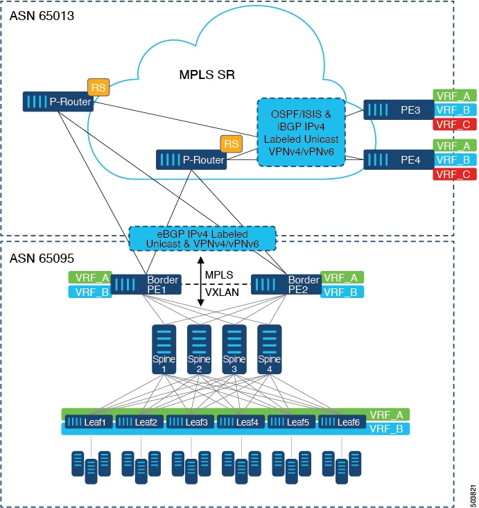
Figure 1. Topology with DC to Core Network Domain Separation

In the above figure, a single Data Center Fabric running VXLAN EVPN is depicted. The VRFs (VRF_A, VRF_B) present in the Data Center require to be extended over a WAN/Core running MPLS-based Segment Routing (MPLS-SR). The Data Center Fabrics Border switches acts as Border Provider Edge (Border PE1, Border PE2) interconnecting VXLAN BGP EVPN with MPLS-SR with L3VPN (VPNv4/VPNv6). The BPEs are interconnected with the Provider Router (P-Router) via eBGP using the IPv4 Labeled-Unicast as well as the VPNv4/VPNv6 Address-Family (AF). The P-Router act as BGP Route-Reflector for the mentioned AF and relays the necessary routes to the MPLS-SR Provider Edge (PE3, PE4) via iBGP. Beyond the usage of BGP as the control-plane, between the MPLS-SR nodes within the same Autonomous System (AS) uses a IGP (OSPF or ISIS) for label distribution. From the PEs shown in the above figure (PE3, PE4), Inter-AS Option A can be used to extend the Data Center or Core network VRFs to another external network. Even as this diagram shows only one Data Center, the MPLS-SR network can be used to interconnect multiple Data Center Fabrics.
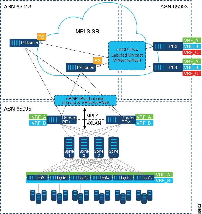
Figure 2. Multiple Administrative Domains within the Core network

An alternative deployment scenario is when the Core network is separate into multiple Administrative Domains or Autonomous Systems (AS). In the above figure, a single Data Center Fabric running VXLAN EVPN is depicted. The VRFs (VRF_A, VRF_B) present in the Data Center requires to be extended over a WAN/Core running MPLS-based Segment Routing (MPLS-SR). The Data Center Fabrics Border switches acts as Border Provider Edge (Border PE1, Border PE2) interconnecting VXLAN BGP EVPN with MPLS-SR with L3VPN (VPNv4/VPNv6). The BPEs are interconnected with the Provider Router (P-Router) via eBGP using the IPv4 Labeled-Unicast as well as the VPNv4/VPNv6 Address-Family (AF). The P-Router act as BGP Route Server for the mentioned AF and relays the necessary routes to the MPLS-SR Provider Edge (PE3, PE4) via eBGP; no other control-plane protocol is used between the MPLS-SR nodes. Similar as in the previous scenario, the PEs (PE3, PE4) can operate with Inter-AS Option A to extend the Data Center or Core network VRFs to external network. Even as this diagram shows only one Data Center, the MPLS-SR network can be used to interconnect multiple Data Center Fabrics.

Beginning with Cisco NX-OS Release 10.3(1)F, DSCP Based SRTE Traffic Steering is supported on the border PE. For more information, see Configuring DSCP Based SRTE Traffic Steering. This scenario is supported only with L3VPN (MPLS SR). In the above diagram, which represents the border PE (border leaf) scenario, note the following:

  1. The incoming VXLAN traffic is terminated and then sent into L3VPN (MPLS SR) so that it follows the standard routing best-path to PE3 or PE4.

  2. Incoming VXLAN traffic entering PE1 is terminated, and the SRTE traffic steering policy applied on L3 VNI overrides the standard routing best-path and steer to choose an alternate path to PE3 or PE4 based on the SRTE flow steering policy.

For additional information on MPLS SR, see the Cisco Nexus 9000 Series NX-OS Label Switching Configuration Guide.

Guidelines and Limitations for Configuring Seamless Integration of EVPN with L3VPN (MPLS SR)

Feature

Cisco Nexus 9300-FX2, FX3, GX, GX2, H2R, H1 Platform Switches

Cisco Nexus 9504 and 9508 switches with -R Line Cards

Comments

VXLAN EVPN to SR-L3VPN

Yes

Yes

Extend Layer 3 connectivity between different DC pods Underlay IGP/BGP with SR extensions.

VXLAN EVPN to SR-L3VPN

Yes

Yes

Extend Layer 3 connectivity between DC POD running VXLAN and any domain (DC or CORE) running SR.

VXLAN EVPN to MPLS L3VPN (LDP)

No

Yes

Underlay is LDP.

The following Cisco Nexus platform switches support seamless integration of EVPN with L3VPN (MPLS SR):

  • 9336C-FX2 switches

  • 93240YC-FX2 switches

  • 9300-FX3 platform switches

  • 9300-GX platform switches

  • 9504 and 9508 platform switches with 96136YC-R and 9636C-RX line cards (The 9636C-R and 9636Q-R line cards are not supported.)

Beginning with Cisco NX-OS Release 10.2(3)F, the seamless integration of EVPN with L3VPN (MPLS SR) is supported on Cisco Nexus 9300-GX2 platform switches.

Beginning with Cisco NX-OS Release 10.4(1)F, the seamless integration of EVPN with L3VPN (MPLS SR) is supported on Cisco Nexus 9332D-H2R switches.

Beginning with Cisco NX-OS Release 10.4(2)F, the seamless integration of EVPN with L3VPN (MPLS SR) is supported on Cisco Nexus 93400LD-H1 switches.

Beginning with Cisco NX-OS Release 10.4(3)F, the seamless integration of EVPN with L3VPN (MPLS SR) is supported on Cisco Nexus 9364C-H1, 9808/9804 switches with X9836DM-A and X98900CD-A line cards.

The following features are supported with seamless integration of EVPN with L3VPN (MPLS SR):

  • Host Facing (Downlinks towards)

    • Individual Layer-3 interfaces (orphan ports)

    • Layer-3 Port-Channel

    • Layer-3 Sub-interfaces

    • Inter-AS Option A (often also called VRF-lite)

  • Core Facing (Uplinks towards VXLAN)

    • Individual Layer-3 interfaces

    • Layer-3 Port-Channel

  • Core Facing (Uplinks towards MPLS SR)

    • Individual Layer-3 interface

    • Per-VRF labels

    • VPN label statistics

  • End-to-EndTime to Live (TTL) and Explicit Congestion Notification (ECN) with pipe-mode only.

  • MPLS SegmentRouting and MPLS LDP cannot be configured at the same time on a Cisco Nexus 9504 and 9508 platform switches with Cisco Nexus 96136YC-R and Cisco Nexus 9636C-RX line cards.

The VXLAN-to-SR handoff QoS value is preserved during handoff and propagated from VXLAN tunnel packets to SR-tunneled packets for Cisco Nexus 9336C-FX2, 93240YC-FX2, 9300-FX3, and 9300-GX platform switches.

Beginning with Cisco NX-OS Release 10.2(3)F, the VXLAN-to-SR handoff QoS value is preserved during handoff and propagated from VXLAN tunnel packets to SR-tunneled packets on Cisco Nexus 9300-GX2 platform switches.

Beginning with Cisco NX-OS Release 10.4(1)F, the VXLAN-to-SR handoff QoS value is preserved during handoff and propagated from VXLAN tunnel packets to SR-tunneled packets on Cisco Nexus 9332D-H2R switches.

Beginning with Cisco NX-OS Release 10.4(2)F, the VXLAN-to-SR handoff QoS value is preserved during handoff and propagated from VXLAN tunnel packets to SR-tunneled packets on Cisco Nexus 93400LD-H1 switches.

Beginning with Cisco NX-OS Release 10.4(3)F, the VXLAN-to-SR handoff QoS value is preserved during handoff and propagated from VXLAN tunnel packets to SR-tunneled packets on Cisco Nexus 9364C-H1 switches.

The following features are not supported with seamless integration of EVPN with L3VPN (MPLS SR):

  • Distributed Anycast Gateway or First-Hop Redundancy Protocol like HSRP, VRRP or GLBP.

  • vPC for redundant Host or Network Service attachment.

  • SVI/Sub-interfaces for Core facing uplinks (MPLS or VXLAN).

  • SVI/Sub-interfaces with configured MAC addresses.

  • Beginning with Cisco NX-OS Release 10.5(3)F, MPLS Segment Routing can be enabled on Border Gateway (BGW for VXLAN Multi-Site). In the earlier releases, MPLS Segment Routing and Border Gateway (BGW for VXLAN Multi-Site) cannot be configured at the same time.

  • Layer-2 for stretched Subnet across the MPLS-SR domain

  • No-drop for VXLAN/SR and SR/VXLAN handoff, for Cisco Nexus 9336C-FX2, 93240YC-FX2, and 9300-FX3 platform switches

  • Statistics, for Cisco Nexus 9504 and 9508 platform switches with 96136YC-R and 9636C-RX line cards

  • Priority flow control (PFC), for Cisco Nexus 9336C-FX2, 93240YC-FX2, 9300-FX3, and 9300-GX platform switches

  • Beginning with Cisco NX-OS Release 10.3(1)F, the DSCP based SRTE traffic steering feature allows source routing of VXLAN packets that are matched using the DSCP fields in the IP header and steered into an SRTE path. Following are the guidelines and limitations for this feature:

    • This feature is supported only on Cisco Nexus 9300-FX2, 9300-FX3, 9300-GX, and 9300-GX2 ToR switches.

    • In case of border leaf or border PE, the ACL filters are applicable on the inner packets (IPv4 access list for IPv4 packets and IPv6 access list for IPv6 packets). This feature is only supported on L3VPN. MPLS EVPN is not supported with VXLAN.

  • Beginning with Cisco NX-OS Release 10.3(2)F, seamless integration of EVPN with L3VPN (MPLS SR) is supported on Cisco Nexus 9300-FX platform switches and Cisco Nexus 9700-FX and 9700-GX line cards. Following are the guidelines and limitations for this feature:

    • When Cisco Nexus 9500 platform switch is in a hand-off mode and the MPLS encapsulated packets are forwarded on an L2 port, the dot1q header does not get added.

    • SVI/Sub-interfaces are not supported for core facing uplinks (MPLS or VXLAN) when Cisco Nexus 9500 platform switch is configured as EVPN to MPLS SR L3VPN hand off mode.

    • The DSCP to MPLS EXP promotion does not work on the FX TOR/line cards in DCI Mode. The copying of Inner DSCP value to MPLS EXP does not work on the FX TOR/line cards in this hand off mode. The MPLS EXP will be set to 0x7.

  • Beginning with Cisco NX-OS Release 10.3(2)F, the DSCP based SR-TE flow steering feature is supported on Cisco Nexus 9300-FX platform switches and Cisco Nexus 9700-FX and 9700-GX line cards. Following are the guidelines and limitations for this feature:

    • When Cisco Nexus 9500 platform switch is in a hand-off mode and the MPLS encapsulated packets are forwarded on an L2 port, the dot1q header does not get added.

    • SVI/Sub-interfaces are not supported for core facing uplinks (MPLS or VXLAN) when Cisco Nexus 9500 platform switch is configured as EVPN to MPLS SR L3VPN hand off mode.

    • The DSCP to MPLS EXP promotion does not work on the FX TOR/line cards in DCI Mode. The copying of Inner DSCP value to MPLS EXP does not work on the FX TOR/line cards in this hand off mode. The MPLS EXP will be set to 0x7.

  • Beginning with Cisco NX-OS Release 10.4(3)F, Cisco Nexus 9808/9804 switches with X9836DM-A and X98900CD-A line cards support the MPLS SR QoS feature only on system level QoS and not at interface level QoS with the following limitations:

    • Default pipe mode is supported, so that the inner packet DSCP or precedence is preserved.

    • For setting MPLS experimental bits in system level QoS policy-map, the following match criteria are supported:

      • Match DSCP

      • Match precedence

    • At system level QoS, the following features are not supported:

      • Policing

      • Policy-map statistics

      • MPLS EXP to DSCP promotion

    • At interface level QoS, the policy with MPLS encapsulation is not supported.

    • Interface level QoS policy take priority over system level QoS policy. Traffic that does not match any criteria in the interface policy will be processed by the default profile in system level QoS.

    • Queuing statistics on MPLS interfaces may erroneously show 'UC ECN Mark pkts'."

Configuring Seamless Integration of EVPN with L3VPN (MPLS SR)

The following procedure for Border Provider Edge (Border PE) imports and reoriginates the routes from the VXLAN domain to the MPLS domain and in the other direction.

SUMMARY STEPS

  1. configure terminal
  2. feature-set mpls
  3. nv overlay evpn
  4. feature bgp
  5. feature mpls l3vpn
  6. feature mpls segment-routing
  7. feature interface-vlan
  8. feature vn-segment-vlan-based
  9. feature nv overlay
  10. router bgp autonomous-system-number
  11. address-family ipv4 unicast
  12. network address
  13. allocate-label all
  14. exit
  15. neighbor address remote-as number
  16. update-source type/id
  17. address-family l2vpn evpn
  18. send-community both
  19. import vpn unicast reoriginate
  20. exit
  21. neighbor address remote-as number
  22. update-source type/id
  23. address-family ipv4 labeled-unicast
  24. send-community both
  25. exit
  26. neighbor address remote-as number
  27. update-source type/id
  28. ebgp-multihop number
  29. address-family vpnv4 unicast
  30. send-community both
  31. import l2vpn evpn reoriginate
  32. exit

DETAILED STEPS

  Command or Action Purpose

Step 1

configure terminal

Example:

switch# configure terminal

Enters global configuration mode.

Step 2

feature-set mpls

Example:

switch(config)# feature-set mpls

Enables the MPLS feature set.

Step 3

nv overlay evpn

Example:

switch(config)# nv overlay evpn

Enables VXLAN.

Step 4

feature bgp

Example:

switch(config)# feature bgp

Enables BGP.

Step 5

feature mpls l3vpn

Example:

switch(config)# feature mpls l3vpn 

Enables Layer 3 VPN.

Note


Feature mpls l3vpn requires feature mpls segment-routing.

Step 6

feature mpls segment-routing

Example:

switch(config)# feature mpls segment-routing

Enables Segment Routing.

Step 7

feature interface-vlan

Example:

switch(config)# feature interface-vlan

Enables the interface VLAN.

Step 8

feature vn-segment-vlan-based

Example:

switch(config)# feature vn-segment-vlan-based

Enables the VLAN-based VN segment.

Step 9

feature nv overlay

Example:

switch(config)# feature nv overlay

Enables VXLAN.

Step 10

router bgp autonomous-system-number

Example:

switch(config)# router bgp 65095

Configures BGP. The value of autonomous-system-number is from 1 to 4294967295.

Step 11

address-family ipv4 unicast

Example:

switch(config-router)# address-family ipv4 unicast

Configures the address family for IPv4.

Step 12

network address

Example:

switch(config-router-af)# network 10.51.0.51/32

Injects prefixes into BGP for the MPLS-SR domain.

Note


All viable next-hops for MPLS-SR tunnel deposition on the Border PE must be advertised via the network statement (/32 only).

Step 13

allocate-label all

Example:

switch(config-router-af)# allocate-label all

Configures label allocation for every prefix injected via the network statement.

Step 14

exit

Example:

switch(config-router-af)# exit

Exits command mode.

Step 15

neighbor address remote-as number

Example:

switch(config-router)# neighbor 10.95.0.95 remote-as 65095

Defines the iBGP neighbor IPv4 address and remote Autonomous-System (AS) number towards the Route-Reflector.

Step 16

update-source type/id

Example:

switch(config-router)# update-source loopback0

Defines the interface for eBGP peering.

Step 17

address-family l2vpn evpn

Example:

switch(config-router)# address-family l2vpn evpn

Configures the L2VPN EVPN address family.

Step 18

send-community both

Example:

switch(config-router-af)# send-community both

Configures the community for BGP neighbors.

Step 19

import vpn unicast reoriginate

Example:

switch(config-router-af)# import vpn unicast reoriginate

Reoriginates the route with a new Route-Target. It can be extended to use an optional route-map.

Step 20

exit

Example:

switch(config-router-af)# exit

Exits command mode.

Step 21

neighbor address remote-as number

Example:

switch(config-router)# neighbor 10.51.131.131 remote-as 65013

Defines the eBGP neighbor IPv4 address and remote Autonomous-System (AS) number towards the P-Router.

Step 22

update-source type/id

Example:

switch(config-router)# update-source Ethernet1/1

Defines the interface for eBGP peering.

Step 23

address-family ipv4 labeled-unicast

Example:

switch(config-router)# address-family ipv4 labeled-unicast

Configures the address family for IPv4 labeled-unicast.

Step 24

send-community both

Example:

switch(config-router-af)# send-community both

Configures the community for BGP neighbors.

Step 25

exit

Example:

switch(config-router-af)# exit

Exits command mode.

Step 26

neighbor address remote-as number

Example:

switch(config-router)# neighbor 10.131.0.131 remote-as 65013

Defines the eBGP neighbor IPv4 address and remote Autonomous-System (AS) number.

Step 27

update-source type/id

Example:

switch(config-router)# update-source loopback0

Defines the interface for eBGP peering.

Step 28

ebgp-multihop number

Example:

switch(config-router)# ebgp-multihop 5

Specifies multihop TTL for the remote peer. The range of numberis from 2 to 255.

Step 29

address-family vpnv4 unicast

Example:

switch(config-router)# address-family vpnv4 unicast

Configures the address family for VPNv4 or VPNv6.

Step 30

send-community both

Example:

switch(config-router-af)# send-community both

Configures the community for BGP neighbors.

Step 31

import l2vpn evpn reoriginate

Example:

switch(config-router-af)# import l2vpn evpn reoriginate

Reoriginates the route with a new Route-Target. It can be extended to use an optional route-map.

Step 32

exit

Example:

switch(config-router-af)# exit

Exits command mode.

Example Configuration for Configuring Seamless Integration of EVPN with L3VPN (MPLS SR)

Scenario - 1 with DC to Core Network Domain Separation and IGP within MPLS-SR network.

Figure 3. Topology with DC to Core Network Domain Separation

The following is a sample CLI configuration that is required to import and reoriginate the routes from the VXLAN domain to the MPLS domain and in the reverse direction. The sample CLI configuration represents only the necessary configuration for the respective roles.

Border PE


hostname BL51-N9336FX2
install feature-set mpls

feature-set mpls

feature bgp
feature mpls l3vpn
feature mpls segment-routing
feature ospf
feature interface-vlan
feature vn-segment-vlan-based
feature nv overlay

nv overlay evpn

mpls label range 16000 23999 static 6000 8000

segment-routing
  mpls
    connected-prefix-sid-map
      address-family ipv4
        10.51.0.51/32 index 51

vlan 2000
  vn-segment 50000

vrf context VRF_A
  vni 50000
  rd auto
  address-family ipv4 unicast
    route-target both auto
    route-target both auto evpn
    route-target import 50000:50000
    route-target export 50000:50000
  address-family ipv6 unicast
    route-target both auto
    route-target both auto evpn
    route-target import 50000:50000
    route-target export 50000:50000

interface Vlan2000
  no shutdown
  vrf member VRF_A
  no ip redirects
  ip forward
  ipv6 address use-link-local-only
  no ipv6 redirects

interface nve1
  no shutdown
  host-reachability protocol bgp
  source-interface loopback1
  member vni 50000 associate-vrf

interface Ethernet1/1
  description TO_P-ROUTER
  ip address 10.51.131.51/24
  mpls ip forwarding
  no shutdown

interface Ethernet1/36
  description TO_SPINE
  ip address 10.95.51.51/24
  ip router ospf 10 area 0.0.0.0
  no shutdown

interface loopback0
  description ROUTER-ID & SR-LOOPBACK
  ip address 10.51.0.51/32
  ip router ospf UNDERLAY area 0.0.0.0

interface loopback1
  description NVE-LOOPBACK
  ip address 10.51.1.51/32
  ip router ospf UNDERLAY area 0.0.0.0

router ospf UNDERLAY
  router-id 10.51.0.51

router bgp 65095
  address-family ipv4 unicast
    network 10.51.0.51/32
    allocate-label all
!
  neighbor 10.95.0.95
    remote-as 65095
    update-source loopback0
    address-family l2vpn evpn
      send-community
      send-community extended
      import vpn unicast reoriginate
!
  neighbor 10.51.131.131
    remote-as 65013
    update-source Ethernet1/1
    address-family ipv4 labeled-unicast
      send-community
      send-community extended
!
  neighbor 10.131.0.131
    remote-as 65013
    update-source loopback0
    ebgp-multihop 5
    address-family vpnv4 unicast
      send-community
      send-community extended
      import l2vpn evpn reoriginate
    address-family vpnv6 unicast
      send-community
      send-community extended
      import l2vpn evpn reoriginate

!
  vrf VRF_A
    address-family ipv4 unicast
      redistribute direct route-map fabric-rmap-redist-subnet

P-Router

hostname P131-N9336FX2
install feature-set mpls

feature-set mpls

feature bgp
feature isis
feature mpls l3vpn
feature mpls segment-routing

mpls label range 16000 23999 static 6000 8000

segment-routing
  mpls
    connected-prefix-sid-map
      address-family ipv4
        10.131.0.131/32 index 131

route-map RM_NH_UNCH permit 10
  set ip next-hop unchanged

interface Ethernet1/1
  description TO_BORDER-PE
  ip address 10.51.131.131/24
  ip router isis 10
  mpls ip forwarding
  no shutdown

interface Ethernet1/11
  description TO_PE
  ip address 10.52.131.131/24
  ip router isis 10
  mpls ip forwarding
  no shutdown

interface loopback0
  description ROUTER-ID & SR-LOOPBACK
  ip address 10.131.0.131/32
  ip router isis 10

router isis 10
  net 49.0000.0000.0131.00
  is-type level-2
  address-family ipv4 unicast
    segment-routing mpls

router bgp 65013
  event-history detail
  address-family ipv4 unicast
    allocate-label all
!
  neighbor 10.51.131.51
    remote-as 65095
    update-source Ethernet1/1
    address-family ipv4 labeled-unicast
      send-community
      send-community extended
!
  neighbor 10.51.0.51
    remote-as 65095
    update-source loopback0
    ebgp-multihop 5
    address-family vpnv4 unicast
      send-community
      send-community extended
      route-map RM_NH_UNCH out
    address-family vpnv6 unicast
      send-community
      send-community extended
      route-map RM_NH_UNCH out
!
  neighbor 10.52.131.52
    remote-as 65013
    update-source Ethernet1/11
    address-family ipv4 labeled-unicast
      send-community
      send-community extended
!
  neighbor 10.52.0.52
    remote-as 65013
    update-source loopback0
    address-family vpnv4 unicast
      send-community
      send-community extended
      route-reflector-client
      route-map RM_NH_UNCH out
    address-family vpnv6 unicast
      send-community
      send-community extended
      route-reflector-client
      route-map RM_NH_UNCH out

Provider Edge (PE)

hostname L52-N93240FX2
install feature-set mpls

feature-set mpls

feature bgp
feature isis
feature mpls l3vpn
feature mpls segment-routing

mpls label range 16000 23999 static 6000 8000

segment-routing
  mpls
    connected-prefix-sid-map
      address-family ipv4
        10.52.0.52/32 index 52

vrf context VRF_A
  rd auto
  address-family ipv4 unicast
    route-target import 50000:50000
    route-target export 50000:50000
  address-family ipv6 unicast
    route-target import 50000:50000
    route-target export 50000:50000

interface Ethernet1/49
  description TO_P-ROUTER
  ip address 10.52.131.52/24
  ip router isis 10
  mpls ip forwarding
  no shutdown

interface loopback0
  description ROUTER-ID & SR-LOOPBACK
  ip address 10.52.0.52/32
  ip router isis 10

router isis 10
  net 49.0000.0000.0052.00
  is-type level-2
  address-family ipv4 unicast
    segment-routing mpls

router bgp 65013
  address-family ipv4 unicast
    network 10.52.0.52/32
    allocate-label all
!
  neighbor 10.52.131.131
    remote-as 65013
    update-source Ethernet1/49
    address-family ipv4 labeled-unicast
      send-community
      send-community extended
!
  neighbor 10.131.0.131
    remote-as 65013
    update-source loopback0
    address-family vpnv4 unicast
      send-community
      send-community extended
    address-family vpnv6 unicast
      send-community
      send-community extended
!
  vrf VRF_A
    address-family ipv4 unicast
      redistribute direct route-map fabric-rmap-redist-subnet

Scenario - 2 with DC to Core and within Core Network Domain Separation (eBGP within MPLS-SR network).

Figure 4. Multiple Administrative Domains within the Core network

The following is a sample CLI configuration that is required to import and reoriginate the routes from the VXLAN domain to the MPLS domain and in the reverse direction. The sample CLI configuration represents only the nodes that are different from Scenario #1, which are the P-Router and the Provider Edge (PE) roles. The Border PE remains the same for both scenarios.

P-Router

hostname P131-N9336FX2
install feature-set mpls

feature-set mpls

feature bgp
feature mpls l3vpn
feature mpls segment-routing

mpls label range 16000 23999 static 6000 8000

segment-routing
  mpls
    connected-prefix-sid-map
      address-family ipv4
        10.131.0.131/32 index 131

route-map RM_NH_UNCH permit 10
  set ip next-hop unchanged

interface Ethernet1/1
  description TO_BORDER-PE
  ip address 10.51.131.131/24
  mpls ip forwarding
  no shutdown

interface Ethernet1/11
  description TO_PE
  ip address 10.52.131.131/24
  mpls ip forwarding
  no shutdown

interface loopback0
  description ROUTER-ID & SR-LOOPBACK
  ip address 10.131.0.131/32
  ip router isis 10

router bgp 65013
  event-history detail
  address-family ipv4 unicast
    network 10.131.0.131/32
    allocate-label all
!
  address-family vpnv4 unicast
    retain route-target all
  address-family vpnv6 unicast
    retain route-target all
!
  neighbor 10.51.131.51
    remote-as 65095
    update-source Ethernet1/1
    address-family ipv4 labeled-unicast
      send-community
      send-community extended
!
  neighbor 10.51.0.51
    remote-as 65095
    update-source loopback0
    ebgp-multihop 5
    address-family vpnv4 unicast
      send-community
      send-community extended
      route-map RM_NH_UNCH out
    address-family vpnv6 unicast
      send-community
      send-community extended
      route-map RM_NH_UNCH out
!
  neighbor 10.52.131.52
    remote-as 65003
    update-source Ethernet1/11
    address-family ipv4 labeled-unicast
      send-community
      send-community extended
!
  neighbor 10.52.0.52
    remote-as 65003
    update-source loopback0
    ebgp-multihop 5
    address-family vpnv4 unicast
      send-community
      send-community extended
      route-map RM_NH_UNCH out
    address-family vpnv6 unicast
      send-community
      send-community extended
      route-map RM_NH_UNCH out

Provider Edge (PE)

hostname L52-N93240FX2
install feature-set mpls

feature-set mpls

feature bgp
feature mpls l3vpn
feature mpls segment-routing

mpls label range 16000 23999 static 6000 8000

segment-routing
  mpls
    connected-prefix-sid-map
      address-family ipv4
        10.52.0.52/32 index 52

vrf context VRF_A
  rd auto
  address-family ipv4 unicast
    route-target import 50000:50000
    route-target export 50000:50000
  address-family ipv6 unicast
    route-target import 50000:50000
    route-target export 50000:50000

interface Ethernet1/49
  description TO_P-ROUTER
  ip address 10.52.131.52/24
  mpls ip forwarding
  no shutdown

interface loopback0
  description ROUTER-ID & SR-LOOPBACK
  ip address 10.52.0.52/32
  ip router isis 10

router bgp 65003
  address-family ipv4 unicast
    network 10.52.0.52/32
    allocate-label all
!
  neighbor 10.52.131.131
    remote-as 65013
    update-source Ethernet1/49
    address-family ipv4 labeled-unicast
      send-community
      send-community extended
!
  neighbor 10.131.0.131
    remote-as 65013
    update-source loopback0
    ebgp-multihop 5
    address-family vpnv4 unicast
      send-community
      send-community extended
    address-family vpnv6 unicast
      send-community
      send-community extended
!
  vrf VRF_A
    address-family ipv4 unicast
      redistribute direct route-map fabric-rmap-redist-subnet

Configuring DSCP Based SR-TE Flow Steering

To configure DSCP based SR-TE flow steering, first configure the border PE or border leaf for seamless integration of EVPN with L3VPN; see Configuring Seamless Integration of EVPN with L3VPN (MPLS SR). Then, to steer the traffic, perform the following configuration:

  1. Configure SRTE policy. See Configuration Process: SRTE Flow-based Traffic Steering section under the Configuring Segment Routing chapter in the Cisco Nexus 9000 Series NX-OS Label Switching Configuration Guide on the Cisco portal.

  2. Configure the L3 VNI interface. See Configuring New L3VNI Mode.

  3. Apply the policy on the L3 VNI interface using the ip/ipv6 policy route-map srte-policy command.

Configuration Example for DSCP Based SR-TE Flow Steering

segment-routing
  traffic-engineering
    segment-list name PATH1
      index 50 mpls label 16100
    segment-list name PATH2
      index 50 mpls label 16500
      index 100 mpls label 16100

    policy blue
      color 202 endpoint 21.1.1.1
      candidate-paths
        preference 100
          explicit segment-list PATH2
    policy red
      color 201 endpoint 21.1.1.1
      candidate-paths
        preference 100
          explicit segment-list PATH1
ip access-list flow-1
  statistics per-entry
  5 permit ip any any dscp af11
ip access-list flow-2	
  statistics per-entry
  5 permit ip any any dscp af12

route-map srte-flow1 permit 10
  match ip address flow-1
  set ip next-hop 61.1.1.1 srte-policy name red

route-map srte-flow1 permit 20
  match ip address flow-2
  set ip next-hop 61.1.1.1 srte-policy name blue 

vrf context 501
  vni 90001 l3

interface vni90001
  ip policy route-map srte-flow1