VXLAN Path Validation and Verification

VXLAN OAM protocols

A VXLAN OAM protocol is a network protocol that

  • enhances the management of VXLAN overlay networks during installation, monitoring, and troubleshooting

  • provides tools similar to ping, traceroute, or pathtrace to help diagnose problems in VXLAN networks, and

  • uses diagnostic channels to trace destinations and carry vital information.

VXLAN OAM is also referred to as NGOAM (Next Generation OAM).

VXLAN OAM Tools

The VXLAN OAM tools are categorized as shown in the table. For more information on OAM tools, see Fault isolation and verification tools.

Table 1. VXLAN OAM Tool Categories

Category

Tools

Fault Verification

Loopback Message

Fault Isolation

Pathtrace Message

VXLAN OAM Payloads

A VXLAN OAM payload is a network protocol element that

  • supports operations, administration, and maintenance functions in overlay networks

  • includes multiple channel types to enable identification of packet payloads, and

  • utilizes reserved identifiers for accurate protocol recognition.

The VXLAN OAM payload supports channel types such as:

  • Conventional ICMP channel: Enables communication with devices using standard ICMP.

  • NVO3 draft Tissa channel: Facilitates advanced diagnostics and communications with supported hosts or switches.

    • Reserved OAM Ether-Type: Identifies OAM packets by protocol encapsulation.

    • Reserved source MAC address: Uses a well-known MAC value for packet recognition.

A VXLAN OAM payload using the reserved OAM Ether-Type field to transmit diagnostic data between overlay network endpoints.

A VXLAN data packet carrying user application data rather than OAM information is not considered a VXLAN OAM payload.

VXLAN OAM payloads are like specialized envelopes used for official system communications, distinct from regular mail carrying personal messages.

Supported platforms and releases for VXLAN NGOAM

This topic lists the Cisco Nexus platforms and the minimum software releases that support VXLAN NGOAM and their limitations if any.

Guidelines and limitations for VXLAN NGOAM

Beginning with Cisco NX-OS Release 10.2(3)F, you do not have to enable the VXLAN feature using the feature nv overlay command to use the NGOAM feature on intermediate nodes.

Supported platforms and releases

Table 2. VXLAN NGOAM support on CloudScale Platform switches

Supported Release

Supported Platform

9.3(3) and later

Cisco Nexus 9300-FX/FX2/GX Series switches

9.3(5) and later

Cisco Nexus 9300-FX3 Series switches

10.2(3)F and later

Cisco Nexus 9300-GX2 Series switches

10.4(1)F and later

Cisco Nexus 9332D-H2R switches

10.4(2)F and later

Cisco Nexus 93400LD-H1 switches

10.4(3)F and later

Cisco Nexus 9364C-H1 switches

Cisco Nexus 9800 Series switches

10.5(2)F and later

Cisco Nexus 9500 platform switches with N9K-X9736C-FX3 line card

10.5(3)F and later

Cisco Nexus 9364E-SG2-Q and 9364E-SG2-O switches

Table 3. VXLAN NGOAM support on Cisco Nexus 9300-SE1 Series switches

Platform

Release

Configure the VXLAN NGOAM

Enable VXLAN Network Operations, Administration, and Maintenance (NGOAM) on a Cisco Nexus switch to support OAM operations and monitoring for VXLAN deployments.

Follow these steps to configure the VXLAN NGOAM on Cisco Nexus switches.

Before you begin

Before you begin, ensure that the VXLAN configuration is complete.

Procedure


Step 1

Enable the NGOAM feature in global configuration mode using the feature ngoam command.

Example:

switch# configure terminal
 switch(config)# feature ngoam

Step 2

(Optional) Verify the NGOAM configuration with the show running-config ngoam command.

Example:

switch# show running-config ngoam

Configure an NGOAM profile

Enable and configure a Network Generic OAM (NGOAM) profile on Cisco Nexus switches for network monitoring and diagnostics.

Perform this task to implement NGOAM features for advanced monitoring and service operations within your Cisco Nexus environment.

Before you begin

Before you begin, ensure the feature ngoam configuration is enabled.

Procedure


Step 1

Run the ngoam profile profile-id command in global configuration mode to create and enable an NGOAM profile.

Example:

switch# configure terminal
switch(config)# feature ngoam
switch(config)# ngoam profile 1
switch(config-ng-oam-profile)# 

Profile ID range: 1 to 1023.

Step 2

Configure the required NGOAM profile options using the relevant sub-commands.

  • description: Add a description to the profile.

  • dot1q: Specify dot1q tag encapsulation.

  • flow: Configure NGOAM flow settings.

  • hop count: Set hop count (range: 1–255).

  • interface: Set the egress interface.

  • oam-channel: Configure the OAM channel.

  • payload: Set the NGOAM payload.

  • sport: Specify UDP source port (range: 1–65535).

Example:

switch(config-ngoam-profile)# oam-channel 2
switch(config-ngoam-profile)# flow forward payload pad 0x2
switch(config-ngoam-profile)# sport 12345, 54321
switch(config-ngoam-profile)# flow forward
switch(config-ng-oam-profile-flow)# oam-channel 2
switch(config-ng-oam-profile-flow)# payload

Step 3

Run the show running-config ngoam command to verify the NGOAM profile configuration.

Example:

switch# show run ngoam
feature ngoam
ngoam profile 1
oam-channel 2
flow forward payload pad 0x2

NGOAM configuration placement in show running-config command output has been updated. Previously, NGOAM configurations appeared before interface configurations. Beginning with Cisco NX-OS Release, 10.6(1)F NGOAM configurations appears after interface-level configurations in the show running-config command output.

  • Example before the change:
    ngoam profile 1
      oam-channel 2
    
    interface Ethernet1/1
      no switchport
      ip address 192.0.2.1/24
      no shutdown
  • Example after the change:
    interface Ethernet1/1
      no switchport
      ip address 192.0.2.1/24
      no shutdown
    
    interface loopback10
      vrf member Org1:vrf1
      ipv6 address 2001:DB8::10/128
    ngoam profile 1
      oam-channel 2

The NGOAM profile is configured and ready for network monitoring operations.

What to do next

Review the NGOAM configuration in the running config and proceed with additional OAM diagnostics as needed.
Fault isolation and verification tools

A fault isolation and verification tool is a network diagnostic utility that

  • quickly identifies problems in IP networks,

  • provides reachability information to hosts and VTEPs within a VXLAN network, and

  • helps pinpoint the location of failures along the data path.

Additional reference information

In VXLAN environments, fault isolation and verification tools include Loopback (Ping) messages for verification and Traceroute or Pathtrace messages for isolating network faults. They are essential for maintaining network reliability and reducing troubleshooting time.

If a loopback test from a source switch to a destination switch fails, use a Traceroute tool to identify the specific switch on the path where the failure occurs.

Tools

Attribute

Verification (Ping)

Isolation (Traceroute/Pathtrace)

Purpose

Checks connectivity

Identifies faulty segment

Message type

ICMP Echo (Ping)

Pathtrace, Traceroute

Usage scenario

End-to-end reachability

Locating problematic device

Ping messages

A ping message is a network diagnostic tool that

  • verifies the reachability of a host on an IP network

  • measures round-trip time for messages sent from the originating host to a destination computer, and

  • helps identify network faults or failures.

A ping message, often called a loopback message, is used by administrators and troubleshooting utilities to check if a device or server is operational and accessible across a network.

If you want to test connectivity between your computer and a website, you can send a ping message to the website’s IP address. If the site is reachable, you will receive a response indicating successful communication.

Ping validation channels

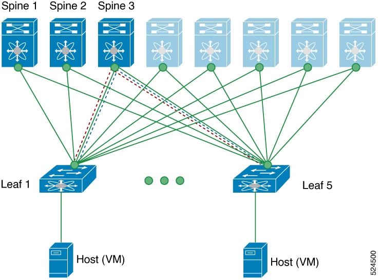
In a Clos network, multiple spine (core) switches connect with several leaf switches to form a scalable data center fabric. Verifying network reachability between leaves (VTEPs) is often performed using ping across different OAM (Operations, Administration, and Maintenance) channels. The two primary channels used for validation are the ICMP channel and the NVO3 Draft Tissa channel.

Table 4. Comparison of ping validation steps on OAM channels

ICMP channel

NVO3 Draft Tissa channel

Loopback message is initiated from Leaf 1 to Leaf 5

Loopback message is initiated from Leaf 1 to Leaf 5

Loopback message is forwarded as VXLAN encapsulated data packet via Spine 3

Loopback message is forwarded as VXLAN encapsulated data packet via Spine 3

Loopback is processed and responded in-band from Leaf 5

  • Message is decapsulated and sent to the host (VM)

  • Host generates the reply and returns it to Leaf 5

  • Reply is processed for the response received from remote VTEP and sent in-band

Loopback response is processed at Leaf 1

Loopback response is processed at Leaf 1

Figure 1. Example: Clos topology for ping validation
text

Traceroute messages

A traceroute message is a network diagnostic tool that

  • traces the route that packets take from a source to a destination,

  • identifies each hop and possible points of failure along the network path, and

  • helps isolate and diagnose connectivity issues.

Traceroute behavior differs between single-site and multisite scenarios, resulting in varying outputs. For more details, see Traceroute functionality in single-site and Traceroute functionality in multi-site.

When an administrator runs a traceroute command, the tool sends probe packets with increasing time-to-live (TTL) values and reports the IP address and response time of each device the packets pass through. This sequence helps pinpoint where delays or failures occur in the network path.

A ping message only checks whether a destination is reachable and does not provide information about the path or intermediate devices between the source and destination. This limits its usefulness compared to traceroute messages for diagnosing network issues.

Traceroute messages

A traceroute message is a network diagnostic tool that

  • traces the path that packets take through a network,

  • validates reachability between source and destination devices, and

  • uses incremental TTL and ICMP responses to identify each network hop.

In VXLAN environments, traceroute messages allow network administrators to verify the end-to-end path between Virtual Tunnel End Points (VTEPs) across overlay networks.

Traceroute messages in a Clos topology
  • A traceroute message is initiated from Leaf 1 (VTEP 1) to Leaf 5 (VTEP 2), traversing Spine 3.

  • The traceroute message is encapsulated in VXLAN and forwarded by the spines based on outer header information.

  • Leaf 5 processes and responds to the in-band traceroute message, confirming path reachability.

Figure 2. Example: Clos topology for traceroute validation
text
Traceroute vs Ping

Traceroute

Ping

Identifies each hop along the network path

Only verifies connectivity between endpoints

Uses increasing TTL values to discover hops

Sends echo requests with constant TTL

Traceroutes in multi-site environments

A traceroute is a network diagnostic tool that

  • identifies the path taken by packets across different devices between source and destination,

  • sends probes with incremented Time To Live (TTL) values to discover each intermediate hop, and

  • provides visibility into how encapsulation (such as VXLAN tunnels) and network boundaries in multi-site environments impact traceability and hop discovery.

VXLAN (Virtual Extensible LAN) encapsulation is commonly used in multi-site environments. When packets are encapsulated, the outer header’s TTL may prevent hop visibility until decapsulation occurs at network boundaries.

In a typical multi-site traceroute process:

  • A UDP probe originates at the source switch or router and is encapsulated in VXLAN at the local leaf.

  • The encapsulated packet traverses the fabric, where intermediate VXLAN tunnel endpoints may not respond to traceroute probes due to outer header TTL handling.

  • At the border gateway (BGW) of a site, the packet is decapsulated, allowing a TTL expiry and thus a response from the BGW node.

  • The packet is re-encapsulated as needed when it continues toward the next site, and responses are seen again at subsequent tunnel endpoints or destination leaves when decapsulation occurs.

In a multi-site Cisco ACI fabric, a traceroute from a workstation in Site 1 to a server in Site 2 shows successful hop discovery within the local site. However, hops inside the VXLAN-encapsulated core are hidden, and responses resume at border gateways and at the destination leaf in Site 2.

Figure 3. Traceroute in a Multi-Site VXLAN Environment

A standard traceroute in a non-encapsulated single-site Layer 2 network produces responses from every hop, as there is no VXLAN tunnel imposing encapsulation-related TTL masking.

Table 5. Traceroutes: Single-Site vs. Multi-Site VXLAN
Attribute Multi-Site VXLAN Single-Site (No VXLAN)
Hop visibility Limited (hidden within tunnels) Full
Encapsulation impact Hides hops within encapsulated segments No encapsulation; all hops revealed

Think of VXLAN encapsulation like a sealed train tunnel: while inside the tunnel, it's impossible to see all the stations the train passes; visibility resumes only when the train exits at another station.

Pathtrace messages

A pathtrace message is a network diagnostic message that

  • enables fault isolation by tracing network paths

  • identifies and reports errors or failures along a route, and

  • provides detailed information to assist in troubleshooting connectivity issues.

Pathtrace messages help network administrators quickly pinpoint issues in complex network topologies by automating error tracing.

If a user reports intermittent connectivity loss between two endpoints, a pathtrace message can be used to trace the exact path, revealing where packets are dropped.

A standard error log is not a pathtrace message because it does not trace the path or provide route-specific failure information.

A pathtrace message is like a breadcrumb trail that highlights obstacles along a route, showing exactly where a traveler encounters problems.

Pathtrace functionalities in single-site deployments

A Pathtrace functionality is a network operations feature that

  • traces the path of packets in a VXLAN overlay network

  • uses the NVO3 draft Tissa channel to gather path information such as ingress and egress interfaces, and

  • responds only up to the VTEP without reaching the host.

Pathtrace is most commonly used within Clos topologies, where multiple spine and leaf switches provide flexible connectivity. The Pathtrace command initiates VXLAN encapsulated packets across the overlay network to deliver path diagnostics up to the VTEP endpoint. Host-level traceability is not supported due to packet termination at VTEP.

Pathtrace does not trace packets all the way to hosts. Instead, tracing always stops at the VTEP, which is the tunnel endpoint in VXLAN overlays.

Pathtrace is like a parcel tracking system that reports delivery to the local distribution center (VTEP) but does not provide updates beyond that point to the final recipient (host).

Pathtrace functionalities in multi-site fabrics

A pathtrace functionality is a network troubleshooting feature that

  • generates diagnostic responses from each node in a multi-site fabric

  • uses the NVO3 channel to enable VXLAN nodes to process packets based on ACL hits instead of TTL expiry, and

  • receives specialized NGOAM handling on Border Gateways to facilitate probe continuation into adjacent fabrics.

Pathtrace is more reliable for deep packet inspection in complex multi-site deployments, since NGOAM ensures probes successfully traverse border gateways and node support for specific protocols is critical.
Figure 4. Pathtrace probe traversal in multi-site fabric environments
Pathtrace probe traversal in multi-site fabric environments

For instance, when a pathtrace probe is sent, each VXLAN-capable node in the fabric can capture and analyze the packet if supported by NGOAM features, providing a complete trace even when TTL does not expire.

Pathtrace does not provide full visibility in fabrics where nodes lack NGOAM support or where ACL processing is not enabled.

Comparison of traceroute and pathtrace message

Table 6. Comparison of Traceroute and Pathtrace Message

Feature

Traceroute Message

Pathtrace Message

Channel Used

ICMP channel

NVO3 draft Tissa channel

Purpose

Fault isolation by discovering the path packets take to reach their destination

Provides additional diagnostic information such as interface load and hop statistics

Behavior on Unsupported Devices

Continues to provide hop information

Behaves as a simple traceroute and provides only hop information

Best practice for fault isolation and verification tools

Ensure that beginning with NX-OS release 9.3(3), you interpret the Received field in the show ngoam pathtrace statistics summary command to include all pathtrace requests received by the node, not just those destined for it. This practice promotes accurate understanding of node activity and improves troubleshooting of network path issues.

Examples for Fault Isolation and Verification Tools

Ping Message Examples

VXLAN OAM provides host visibility at the switch level, allowing verification of host connectivity using the ping nve command. The following examples demonstrate typical command usage and output for different VXLAN OAM scenarios.

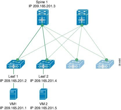
VXLAN network topology for OAM ping operation
  • Ping from Leaf 1 to VM2 via Spine 1 using channel 1 (unique loopback)

    switch# ping nve ip 209.165.201.5 vrf vni-31000 source 1.1.1.1 verbose
    
    Codes: '!' - success, 'Q' - request not sent, '.' - timeout, 'D' - Destination Unreachable, 'X' - unknown return code, 'm' - malformed request(parameter problem),
    'c' - Corrupted Data/Test, '#' - Duplicate response
    
    
    Sender handle: 34
    ! sport 40673 size 39,Reply from 209.165.201.5,time = 3 ms
    ! sport 40673 size 39,Reply from 209.165.201.5,time = 1 ms
    ! sport 40673 size 39,Reply from 209.165.201.5,time = 1 ms
    ! sport 40673 size 39,Reply from 209.165.201.5,time = 1 ms
    ! sport 40673 size 39,Reply from 209.165.201.5,time = 1 ms
    Success rate is 100 percent (5/5), round-trip min/avg/max = 1/4/18 ms Total time elapsed 49 ms
    

    Note


    The source ip-address 1.1.1.1 used in this example is a loopback interface configured on Leaf 1 in the same VRF as the destination IP address. For example, the VRF in this example is vni-31000.


    switch# ping nve ip unknown vrf vni-31000 payload ip 209.165.201.5 209.165.201.4 payload-end verify-host
    <snip>
    Sender handle: 34
    !!!!!
    Success rate is 100 percent (5/5), round-trip min/avg/max = 1/4/18 ms Total time elapsed 49 ms
    
  • MAC ping from Leaf 2 to Leaf 1 using NVO3 Draft Tissa channel

    switch# ping nve mac 0050.569a.7418 2901 ethernet 1/51 profile 4 verbose
    
    Codes: '!' - success, 'Q' - request not sent, '.' - timeout, 'D' - Destination Unreachable, 'X' - unknown return code, 'm' - malformed request(parameter problem),
    'c' - Corrupted Data/Test, '#' - Duplicate response
    
    Sender handle: 408
    !!!!Success rate is 100 percent (5/5), round-trip min/avg/max = 4/4/5 ms Total time elapsed 104 ms
    
    switch# show run ngoam
    feature ngoam ngoam profile 4
    oam-channel 2 ngoam install acl
    

Traceroute message examples

This reference explains the codes used in traceroute output, and provides examples of command output from a Leaf-Spine-VM network topology.

Example: traceroute command output
switch# traceroute nve ip 209.165.201.5 vrf vni-31000 source 1.1.1.1 verbose
Codes: '!' - success, 'Q' - request not sent, '.' - timeout, 'D' - Destination Unreachable, 'X' - unknown return code, 'm' - malformed request(parameter problem),
'c' - Corrupted Data/Test, '#' - Duplicate response

Traceroute request to peer ip 209.165.201.4 source ip 209.165.201.2 Sender handle: 36
1 !Reply from 209.165.201.3,time = 1 ms
2 !Reply from 209.165.201.4,time = 2 ms
3 !Reply from 209.165.201.5,time = 1 ms

Pathtrace message examples

This reference explains the codes used in pathtrace output, and provides examples of command output from a Leaf-Spine-VM network topology.

Example: pathtrace command output

  • Pathtrace based on a payload from Leaf 2 to Leaf 1

    switch# pathtrace nve ip 209.165.201.4 vni 31000 verbose
    Path trace Request to peer ip 209.165.201.4 source ip 209.165.201.2 Sender handle: 42
    Hop Code	ReplyIP	IngressI/f	EgressI/f	State
    ======================================================================
    1	!Reply from 209.165.201.3, Eth5/5/1	Eth5/5/2	UP/UP
    2	!Reply from 209.165.201.4, Eth1/3	Unknown	UP/DOWN

    Note


    When the total hop count to the final destination is more than 5, the path trace default TTL value is 5. Use the max-ttl option to complete the VXLAN OAM path trace completely.

    For example: pathtracenve ip unknown vrf vrf-vni13001 payload ip 200.1.1.71 200.1.1.23 payload-end verbose max-ttl 10
  • Pathtrace NVE MAC
    switch# pathtrace nve mac 0050.569a.d927 11 payload mac-addr 0050.569a.d927 0050.569a.a4fa payload-end vni 31000 verbose
    
    Codes: '!' - success, 'Q' - request not sent, '.' - timeout, 'D' - Destination Unreachable, 'X' - unknown return code, 'm' - malformed request(parameter problem),
    'c' - Corrupted Data/Test, '#' - Duplicate response, 'v' - Other - Use verbose to see the result
    
    Path trace Request to peer ip 209.165.201.4 source ip 209.165.201.2 Sender handle: 46
    Hop Code Reply	IngressI/f EgressI/f State
    ======================================================================
    1 !Reply from 209.165.201.3, Eth5/5/1 Eth5/5/2 UP/UP
    2 !Reply from 209.165.201.4, Eth1/3	Unknown UP/DOWN
    

    Note


    When the total hop count to the final destination is more than 5, the path trace default TTL value is 5. Use max-ttl option to finish VXLAN OAM path trace completely.

    For example: pathtrace nve ip unknown vrf vrf-vni13001 payload ip 200.1.1.71200.1.1.23 payload-end verbose max-ttl 10


VXLAN EVPN Loop Detection and Mitigation

Network loops

A network loop is a networking topology problem that

  • occurs when redundant network connections create a circular path for data packets

  • allows broadcast frames to be continuously bridged within the loop, and

  • can lead to congestion and severe disruption of network services.

In a VXLAN EVPN fabric, network loops usually happen because of incorrect cabling on the south (access) side of the fabric. When a broadcast packet enters a network with a loop, the frame circulates endlessly, resulting in the accumulation of broadcast traffic. Over time, these accumulated frames can overwhelm network resources and seriously disrupt services.

If two switches are accidentally connected with multiple cables, a broadcast frame can move in circles between them, multiplying rapidly and causing a broadcast storm.

A correctly configured network using loop prevention protocols, such as Spanning Tree Protocol (STP), does not experience continuous looping of broadcast frames because redundant paths are intentionally blocked.

VXLAN EVPN loop detection and mitigation

A VXLAN EVPN loop detection and mitigation feature is a network resiliency mechanism that

  • detects Layer 2 loops in a single VXLAN EVPN fabric or a multi-site environment,

  • automatically disables affected VLANs on the ports where a loop is detected and notifies administrators, and

  • clears incorrectly learned local and remote MAC address entries to maintain forwarding accuracy and service availability.

This feature operates at the port/VLAN level and is introduced in Cisco NX-OS Release 9.3(5). Administrators receive syslog notifications when loops are detected or cleared.

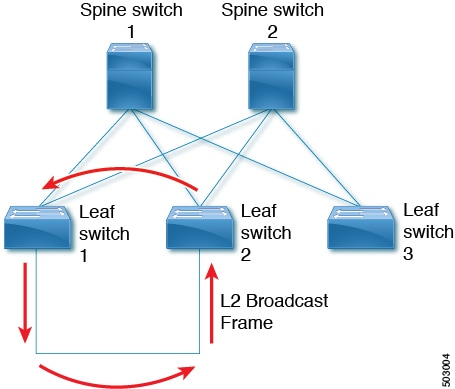
A common scenario occurs when incorrect cabling directly connects two leaf devices on the access (south) side of the fabric. In such cases, a broadcast frame may be repeatedly forwarded between the leaves, causing a loop. The loop detection mechanism identifies this and triggers VLAN suspension and MAC address flushing.

Figure 5. Two Leaf Nodes Directly Connected

Various Loop Scenarios:

This feature operates in three phases:

  1. Loop Detection: Probes are sent when requested by a client, periodically, or when any port comes online.

  2. Loop Mitigation: When a loop is found, affected VLANs are blocked and syslog alerts are generated. Incorrect MAC entries are flushed to prevent mislearning.
    2020 Jan 14 09:58:44 Leaf1 %NGOAM-4-SLD_LOOP_DETECTED: Loop detected - Blocking vlan 1001 :: Eth1/3
    or
    2024 Sep  9 15:28:01 Node-11 %ETHPORT-3-IF_ERROR_VLANS_SUSPENDED: VLANs 2704 on Interface Ethernet1/49/1 are being suspended. (Reason: SUCCESS)

    Because loops can lead to incorrect local MAC address learning, this phase also flushes the local and remote MAC addresses. Doing so removes any MAC addresses that are incorrectly learned.

    In the previous figure, MAC addresses can be incorrectly learned because packets from hosts sitting behind the remote leaf (Leaf3) can reach both Leaf1 and Leaf2 from the access side. As a result, the hosts incorrectly appear local to Leaf1 and Leaf2, which causes the leafs to learn their MAC addresses.

  3. Loop Recovery: After a recovery interval, probe messages determine if the loop persists. Service is restored and administrators are notified when the loop is cleared.

    2020 Jan 14 09:59:38 Leaf1 %NGOAM-4-SLD_LOOP_GONE: Loop cleared - Enabling vlan 1001 :: Eth1/3
    or
    2024 Sep  9 15:24:23 Node-11 %ETHPORT-3-IF_ERROR_VLANS_REMOVED: VLANs 384 on Interface Ethernet1/49/1 are removed from suspended state.

    Note


    The default logging level for NGOAM does not generate a syslog message. Modifying the logging level of NGOAM to 5 with "logging level ngoam 5" will result in a syslog message being generated when a loop is detected.


Networks that lack this feature may not automatically block VLANs or notify administrators when loops occur, increasing the risk of service disruption.

When a fault (loop) is detected, the relevant circuit (VLAN) is quickly deactivated, and service is restored once the problem is resolved.

Southbound loop detection on Layer-3 interfaces

A southbound loop detection on Layer-3 interface mechanism is a network feature that

  • isolates a single Layer-3 attached tenant to prevent the impact of storms from propagating beyond a Layer-3 boundary due to control-plane policing congestion,

  • detects downstream Layer-2 loops and blocks the attached Layer-3 interface or Layer-3 port-channel if a loop is detected by receipt of an originated NGOAM probe, and

  • unblocks the Layer-3 port if the originated NGOAM probes are no longer detected.

Beginning with NX-OS release 10.4(3)F, Cisco Nexus switches support Southbound Loop Detection (SLD) on a Layer-3 (L3) Ethernet and L3 port-channel interfaces in a single VXLAN EVPN fabric or a Multi-Site environment. Before this release, the SLD feature was supported only on Layer-2 interfaces.

When SLD is enabled on a Layer-3 interface, it periodically sends probes to monitor for loops within the downstream Layer-2 tenant domain. If a loop is detected, the mechanism automatically blocks the Layer-3 interface to prevent network disruption, requiring manual corrective action to restore connectivity.

SLD Layer-3 interface loop protection mechanisms

SLD Layer-3 interfaces provide automatic protection for leaf switches and their connected Layer-2 domains by detecting, mitigating, and recovering from bridging loop events without manual intervention.

Key behaviors of SLD Layer-3 interfaces include:

  • Loop detection: The interface periodically sends probes to downstream Layer-2 switches to check for bridging loops.

    Loop detection is triggered when:

    • Requested by a client

    • A scheduled probe interval occurs

    • A port transitions to the up state

    If a bridging loop is created (for example, by disabling STP on a VLAN or a cabling error), SLD detects symptoms such as continuous MAC moves and ARP storms.

    Example syslog output:

    2024 Jun 27 02:34:39 tenant2 %L2FM-2-L2FM_CONTINUOUS_MAC_MOVE: Mac Address (f80f.6f96.a127) in Vlan 101 is moving continuously. Mac moved between Eth1/32 to Eth1/31. Please enable 'logging level l2fm 4' for verbose output.

  • Loop mitigation: When a loop is confirmed, the SLD Layer-3 interface automatically blocks the affected port and generates corresponding syslog messages.

    Example syslog outputs:

    2024 Jun 27 02:37:50 leaf %ETHPORT-5-IF_DOWN_NONE: Interface Ethernet1/2 is down (None)
    2024 Jun 27 02:37:50 leaf %ETHPORT-5-IF_DOWN_ERROR_DISABLED: Interface Ethernet1/2 is down (Error disabled. Reason:error)
    2024 Jun 27 02:38:52 leaf %ETHPORT-5-IF_ERRDIS_RECOVERY: Interface Ethernet1/2 is being recovered from error disabled state (Last Reason:error)
    2024 Jun 27 02:38:54 leaf %ETHPORT-5-IF_DOWN_ERROR_DISABLED: Interface Ethernet1/2 is down (Error disabled. Reason:error)
    !
    leaf# show ngoam loop-detection status l3 
    Port       Status       NumLoops      DetectionTime             ClearedTime
    ========================================================================================
    
    Eth1/2     BLOCKED      2             Tue Jun 27 02:38:54 2024  Tue Jun 27 02:38:52 2024

    After each recovery interval, the blocked port is temporarily enabled to send probes and recheck for the loop. If the issue persists, the port returns to the blocked state.

    For example: the Eth1/2 L3 interface is moved from the Blocked state to the Forwarding state. The probe checks for the loop, and if the loop still exists, it moves the eth1/2 L3 interface back to the Blocked state.

    The sample output displays the state (blocking and unblocking) based on the probe generated:

    2024 Jun 27 20:26:56 leaf %NGOAM-4-SLD_L3_LOOP_DETECTED: Loop detected - Blocking port Eth1/2
    2024 Jun 27 20:26:56 leaf %ETHPORT-5-IF_DOWN_NONE: Interface Ethernet1/2 is down (None)
    2024 Jun 27 20:26:56 leaf %ETHPORT-5-IF_DOWN_ERROR_DISABLED: Interface Ethernet1/2 is down (Error disabled. Reason:error)
    2024 Jun 27 20:27:58 leaf %ETHPORT-5-IF_ERRDIS_RECOVERY: Interface Ethernet1/2 is being recovered from error disabled state (Last Reason:error)
    2024 Jun 27 20:27:58 leaf %NGOAM-4-SLD_L3_LOOP_GONE: Loop cleared - Enabling port Eth1/2
    2024 Jun 27 20:28:00 leaf %NGOAM-4-SLD_L3_LOOP_DETECTED: Loop detected - Blocking port Eth1/2
    2024 Jun 27 20:28:01 leaf %ETHPORT-5-IF_DOWN_ERROR_DISABLED: Interface Ethernet1/2 is down (Error disabled. Reason:error)
    
  • Loop recovery: When the external loop is physically corrected (for example, through cabling or re-enabling STP), SLD recovery probes confirm resolution. The port is returned to the forwarding state and normal operation resumes.

    Example syslog output:

    2024 Jun 27 22:39:26 tenant2 %ETHPORT-5-IF_DOWN_ADMIN_DOWN: Interface Ethernet1/32 is down (Administratively down)
    2024 Jun 27 22:39:56 tenant2 %ETHPORT-5-SPEED: Interface Ethernet1/2, operational speed changed to 10 Gbps
    2024 Jun 27 22:39:56 tenant2 %ETHPORT-5-IF_DUPLEX: Interface Ethernet1/2, operational duplex mode changed to Full
    2024 Jun 27 22:39:56 tenant2 %ETHPORT-5-IF_RX_FLOW_CONTROL: Interface Ethernet1/2, operational Receive Flow Control state changed to off
    2024 Jun 27 22:39:56 tenant2 %ETHPORT-5-IF_TX_FLOW_CONTROL: Interface Ethernet1/2, operational Transmit Flow Control state changed to off
    2024 Jun 27 22:39:56 tenant2 %ETHPORT-5-IF_UP: Interface Ethernet1/17 is up
    2024 Jun 27 22:41:03 tenant2 %VSHD-5-VSHD_SYSLOG_CONFIG_I: Configured from vty by admin on 10.82.195.201@pts/2
Advantages of SLD Layer-3 interface loop protection
  • Minimizes downtime by automatically isolating and recovering from faults without manual intervention.

  • Provides syslog and operational feedback for rapid troubleshooting.

  • Reduces impact from accidental VLAN misconfiguration or cabling errors across tenants served by the leaf switch.


Note


For increased visibility, set the logging level for NGOAM to 5 (logging level ngoam 5 ) to generate immediate syslog messages when a loop is detected.


Typical topology

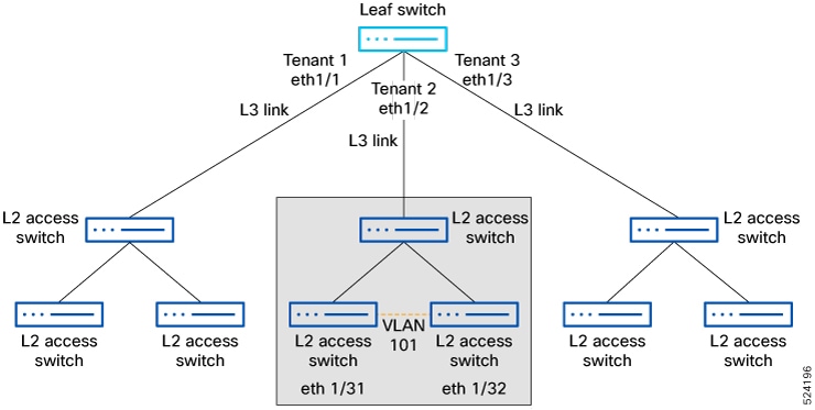
An EVPN fabric may contain a leaf switch configured with multiple VRFs (Tenant 1, Tenant 2, and Tenant 3) connected to separate Layer-2 access switches via dedicated Layer-3 interfaces. Each Layer-3 interface protects its downstream Layer-2 domain independently.

Figure 6. EVPN fabric topology with SLD Layer-3 interfaces
EVPN fabric topology with SLD Layer-3 interfaces

Comparison of L2 and L3 SLD feature functionality

Storm Loop Detection (SLD) enables loop detection and mitigation at different network layers to protect network stability. The following table provides a side-by-side comparison of SLD feature functionality between Layer 2 (L2) and Layer 3 (L3) interfaces:
Table 7. L2 and L3 SLD Feature Functionality Comparison

Features

SLD on L2 Interface

SLD on L3 Interface

Operation level

Port and VLAN level

Ethernet and L3 port-channel

Environment

Single-Site and Multi-Site

Single-Site and Multi-Site

Loop detection

Detects the loop of a particular port or VLAN

Detects downstream L2 loops and blocks the L3 interfaces or L3 port channels

Loop mitigation

Blocks the VLANs on a port once a loop has been discovered and displays a syslog message

Isolates a single L3 attached tenant to prevent the impact of a storm from propagating beyond a single L3 boundary by consuming shared CoPP policer resources

Loop blocking

Breaks the southbound loops

Isolates detected loops from impacting the control plane by shedding storm-related traffic

Loop recovery

Sends recovery probes, re-enables VLANs, and logs syslog messages once the loop is cleared

Sends recovery probes, re-enables the port or ethernet interfaces if the NGOAM process no longer sees NGOAM probes, and logs syslog messages once the loop is cleared

Supported features and limitations for VXLAN EVPN loop detection and mitigation

VXLAN EVPN loop detection and mitigation supports specific environments and has configuration requirements and feature limitations you must follow to ensure proper operation.

Functional guidelines

  • VXLAN EVPN loop detection and mitigation is supported in both STP and STP-less environments.

  • For VXLAN EVPN Multi-Site deployments, configure the ngoam loop-detection command on all border gateways in each site where this feature is deployed to enable loop detection across sites.

Unsupported features

Functional guidelines and unsupported features for VXLAN EVPN loop detection and mitigation:

  • VXLAN EVPN loop detection and mitigation isn't supported with the following features:

    • Private VLANs

    • VLAN translation

    • ESI-based multihoming

    • VXLAN Cross Connect

    • Q-in-VNI

    • EVPN segment routing (Layer 2)

Exclusion requirements

You must exclude ports or VLANs configured with any unsupported features from VXLAN EVPN loop detection and mitigation.

Use the following command to exclude VLANs and ports:

disable {vlan vlan-range} [port port-range] 

Supported platform and release for VXLAN EVPN loop detection and mitigation

The supported Cisco Nexus platforms and software releases for VXLAN EVPN loop detection and mitigation are as mentioned in this table.

Table 8. Supported Platform and Release for VXLAN EVPN Loop Detection and Mitigation
Supported Release Supported Platform
9.3(5) and later

Cisco Nexus 9300-EX/FX/FX2 and 9332C and 9364C Series switches

Cisco Nexus 9500 platform switches with 9700-EX/FX line cards

10.1(1) and later Cisco Nexus 9300-FX3/GX Series switches
10.2(3)F and later Cisco Nexus 9300-GX2 Series switches
10.4(1)F and later Cisco Nexus 9332D-H2R Series switches
10.4(2)F and later Cisco Nexus 93400LD-H1 Series switches
10.4(3)F and later Cisco Nexus 9364C-H1 Series switches

10.5(2)F and later

Cisco Nexus 9500 platform switches with 9700-FX3 line cards

SLD support on L3 interfaces

SLD is supported only on the following Layer 3 interface types:

  • L3 ethernet interfaces

  • L3 port-channel interfaces

SLD is not supported on:

  • L3 sub-interfaces

Supported platform and release for SLD on L3 interface

Release

Platform

10.4(3)F and later

Cisco Nexus 9300-EX/FX/FX2/GX/GX2/H2R/H1, 9332C and 9364C Series switches

Cisco Nexus 9500 platform switches with 9700-EX/FX/GX line cards

10.5(2)F and later

Cisco Nexus 9500 platform switches with 9700-FX3 line cards

Configuration requirements for NGOAM Southbound loop detection

Before enabling NGOAM Southbound loop detection, ensure the following requirements are met:

  • The NGOAM feature is enabled.

  • The TCAM "ing-sup" region has adequate space, which can be set using the hardware access-list tcam region ing-sup 768 command.


    Note


    • Ensure that additional TCAM entries are freed up before increasing the allocation for the ing-sup region.

    • Configuring the TCAM region requires the node to be rebooted.


Configure NGOAM Southbound loop detection on Layer-2 interfaces

Perform this task to protect your network from broadcast storms and other issues caused by Layer-2 loops using the NGOAM feature.

Follow these steps to configure NGOAM Southbound loop detection and mitigation.

Procedure


Step 1

Enable NGOAM Southbound loop detection and mitigation for all VLANs or ports.

Example:

switch# configure terminal
switch(config)# ngoam loop-detection
switch(config-ng-oam-loop-detection)#

This feature is disabled by default.

To disable the feature, use the no ngoam loop-detection command.

Step 2

(Optional) Disable NGOAM Southbound loop detection for specific VLANs or ports and bring up any loop-detected ports.

Example:

Disables on specific VLAN ports:
switch(config-ng-oam-loop-detection)# disable vlan 1200 port ethernet 1/1
Disables on specific VLANs:
switch(config-ng-oam-loop-detection)# disable vlan 1300

To resume active monitoring, use the no form of the command.

Step 3

(Optional) Set how often periodic loop-detection probes are sent.

Example:

switch(config-ng-oam-loop-detection)# periodic-probe-interval 200

Range: 60 seconds to 3600 seconds (60 minutes). Default: 300 seconds (5 minutes).

Step 4

(Optional) Set the frequency of recovery probes when a port or VLAN is shut down.

Example:

switch(config-ng-oam-loop-detection)# port-recovery-interval 300

Range: 300 seconds to 3600 seconds (60 minutes). Default value: 600 seconds (10 minutes).

Step 5

(Optional) Verify the loop-detection configuration and current loop status.

Example:

switch# show ngoam loop-detection summary
Loop detection:enabled
Periodic probe interval: 200
Port recovery interval: 300
Number of vlans: 1
Number of ports: 1
Number of loops: 1
Number of ports blocked: 1
Number of vlans disabled: 0
Number of ports disabled: 0
Total number of probes sent: 214
Total number of probes received: 102
Next probe window start: Thu May 14 15:14:23 2020 (0 seconds)
Next recovery window start: Thu May 14 15:54:23 2020 (126 seconds)

NGOAM Southbound loop detection and mitigation are enabled and configured for your Layer-2 interfaces.

What to do next

Configure a QoS policy on the spine. (For configuration example, see Commands for NGOAM loop detection and mitigation).

Configure NGOAM Southbound loop detection on Layer-3 interfaces

Enable NGOAM Southbound loop detection (SLD) on Layer-3 Ethernet and port-channel interfaces to proactively identify and resolve network loops in downstream Layer-2 domains.

  • NGOAM SLD sends periodic probes and continues monitoring until the user takes corrective action.

Follow these steps to configure NGOAM Southbound loop detection on Layer-3 interfaces:

Procedure


Step 1

Enable NGOAM Southbound loop detection and mitigation for all VLANs or ports.

Example:

switch# configure terminal
switch(config)# ngoam loop-detection
switch(config-ng-oam-loop-detection)#

This feature is disabled by default.

To disable the feature, use the no ngoam loop-detection command.

Step 2

Enable L3 loop detection on Ethernet interfaces.

Example:

switch(config-ng-oam-loop-detection)# l3 ethernet port Eth1/49

To disable, use the no form of this command.

Step 3

Enable L3 loop detection on port-channel interfaces.

Example:

switch(config-ng-oam-loop-detection)# l3 port-channel port port-channel1

To disable, use the no form of this command.

Step 4

(Optional) Verify detected loops on L3 interfaces.

Example:

switch# show ngoam loop-detection status l3
Port       Status       NumLoops      DetectionTime             ClearedTime
========================================================================================
 Eth1/2     BLOCKED      2             Tue Jun 25 02:38:54 2024  Tue Jun 25 02:38:52 2024

Step 5

(Optional) Verify loop-detection configuration and view current summary.

Example:

switch# show run ngoam
ngoam loop-detection
  periodic-probe-interval 60
  port-recovery-interval 600
  l3 ethernet port Ethernet1/1-3
!
2024 Jun 25 02:37:50 switch %ETHPORT-5-IF_DOWN_NONE: Interface Ethernet1/2 is down (None)
2024 Jun 25 02:37:50 switch %ETHPORT-5-IF_DOWN_ERROR_DISABLED: Interface Ethernet1/2 is down (Error disabled. Reason:error)
2024 Jun 25 02:38:52 switch %ETHPORT-5-IF_ERRDIS_RECOVERY: Interface Ethernet1/2 is being recovered from error disabled state (Last Reason:error)
2024 Jun 25 02:38:54 switch %ETHPORT-5-IF_DOWN_ERROR_DISABLED: Interface Ethernet1/2 is down (Error disabled. Reason:error)

NGOAM Southbound Loop Detection is enabled and actively monitors the configured L3 Ethernet and port-channel interfaces for loops. Verification commands show current status and configuration.

Detect loops and bring up ports on demand

Use this task when you need to manually check for loops on your switch and re-enable ports affected by loop-detection mechanisms.

Follow the steps to detect loops or bring up blocked ports on demand.

Before you begin

Make sure you have administrative access to the switch CLI.

Procedure


Step 1

(Optional) Send a loop-detection probe on the target VLAN or port by running the ngoam loop-detection probe command.

Example:

switch# ngoam loop-detection probe vlan 1200 port ethernet 1/1

The switch notifies you if the probe was successfully sent.

Step 2

(Optional) Bring up one or more previously blocked VLANs or ports by running the ngoam loop-detection bringup command.

Example:

switch# ngoam loop-detection bringup vlan 1200 port ethernet 1/1

This command also clears any entries stuck in the NGOAM.

Note


Ports may take up to two port-recovery intervals to come up. To speed up recovery, reissue this command to override the timer. .

Step 3

(Optional) Verify the loop-detection status using the show ngoam loop-detection status command, with or without the history option.

Example:

Without history option
switch# show ngoam loop-detection status
VlanId Port   Status     NumLoops  Detection Time                ClearedTime
====== ====== ========== ========= ============================= ===============
100    Eth1/3 BLOCKED     1        Tue Apr 14 20:07:50.313 2020  Never
With history option
switch# show ngoam loop-detection status history
VlanId Port   Status     NumLoops  Detection Time                ClearedTime
====== ====== ========== ========= ============================= ===============
100    Eth1/3 BLOCKED     1        Tue Apr 14 20:07:50.313 2020  Never
200    Eth1/2 FORWARDING  1        Tue Apr 14 21:19:52.215 2020  May 11 21:30:54.830 2020

The status can be one of the following:

  • BLOCKED: The VLAN or port is shut down because a loop has been detected.

  • FORWARDING: A loop has not been detected, and the VLAN or port is operational.

  • RECOVERING: Recovery probes are being sent to determine if a previously detected loop still exists.

The history option displays blocked, forwarding, and recovering ports. Without the history option, the command displays only blocked and recovering ports.


You identify network loops and re-enable ports once it is safe, restoring normal network operation.

Commands for NGOAM loop detection and mitigation

This section provides essential configuration and monitoring commands for NGOAM southbound loop detection and mitigation in VXLAN EVPN environments. Use these commands to enable loop detection features, configure operational parameters, disable detection on specific VLANs or ports, apply QoS policy, and verify system status.

Configuration commands

  • Enable loop detection and configure intervals:
    
    switch(config)# ngoam loop-detection
    switch(config-ng-oam-loop-detection)# periodic-probe-interval 200
    switch(config-ng-oam-loop-detection)# port-recovery-interval 300
  • Disable loop detection on specific VLANs or ports:
    
    switch(config-ng-oam-loop-detection)# disable vlan 1200 port ethernet 1/1
    switch(config-ng-oam-loop-detection)# disable vlan 1300
  • Configure and apply a QoS policy for loop-detection-enabled links:

    Defines a QoS classification and policy, then applies it to spine interfaces for optimized traffic handling.
    class-map type qos match-any Spine-DSCP56
    match dscp 56
    policy-map type qos Spine-DSCP56
    class Spine-DSCP56
    set qos-group 7
    
    interface Ethernet1/31
    mtu 9216
    no link dfe adaptive-tuning
    service-policy type qos input Spine-DSCP5663
    no ip redirects
    ip address 27.4.1.2/24
    ip router ospf 200 area 0.0.0.0
    ip pim sparse-mode
    no shutdown

Verification commands and outputs

  • Show loop detection summary:

    Displays loop detection status, probe intervals, blocked ports, sent/received probe counts, and timer information.
    switch# show ngoam loop-detection summary
    Loop detection:enabled
    Periodic probe interval: 200
    Port recovery interval: 300
    Number of vlans: 1
    Number of ports: 1
    Number of loops: 1
    Number of ports blocked: 1
    Number of vlans disabled: 0
    Number of ports disabled: 0
    Total number of probes sent: 214
    Total number of probes received: 102
    Next probe window start: Thu May 14 15:14:23 2020 (0 seconds)
    Next recovery window start: Thu May 14 15:54:23 2020 (126 seconds)
  • Show loop detection status for VLANs and interfaces, with and without history option:

    Displays loop status for VLANs and interfaces, with details about current and cleared events.
    switch# show ngoam loop-detection status
    VlanId Port   Status     NumLoops  Detection Time                ClearedTime
    ====== ====== ========== ========= ============================= ===============
    100    Eth1/3 BLOCKED     1        Tue Apr 14 20:07:50.313 2020  Never
    
    switch# show ngoam loop-detection status history
    VlanId Port   Status     NumLoops  Detection Time                ClearedTime
    ====== ====== ========== ========= ============================= ===============
    100    Eth1/3 BLOCKED     1        Tue Apr 14 20:07:50.313 2020  Never
    200    Eth1/2 FORWARDING  1        Tue Apr 14 21:19:52.215 2020  May 11 21:30:54.830 2020