Configure VXLAN EVPN Traffic Engineering - Multi-Site Egress Load Balancing

This chapter describes how to configure the VXLAN EVPN Traffic Engineering (TE) - Multi-Site Egress Load-Balancing feature on Cisco NX-OS devices.

VXLAN EVPN TE multi-site egress load balancing

A VXLAN EVPN TE - Multi-Site egress load balancing mechanism is a networking technology that

  • facilitates traffic steering between data center sites

  • enables load balancing for data transmitted across different fabrics over multi-site links, and

  • operates across an IP-based underlay network (Inter-site Network, or ISN) to provide IP traffic engineering for overlay-encapsulated traffic.

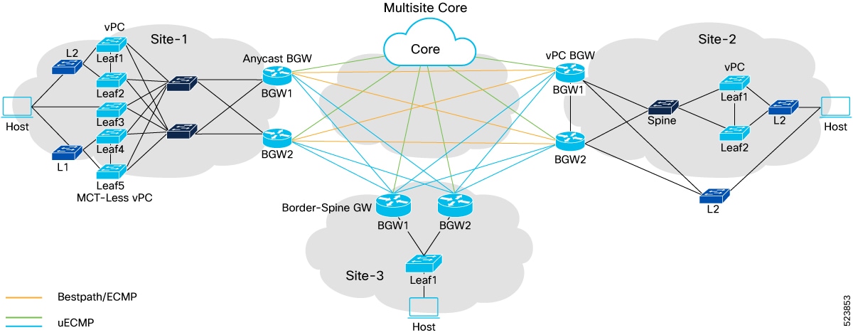
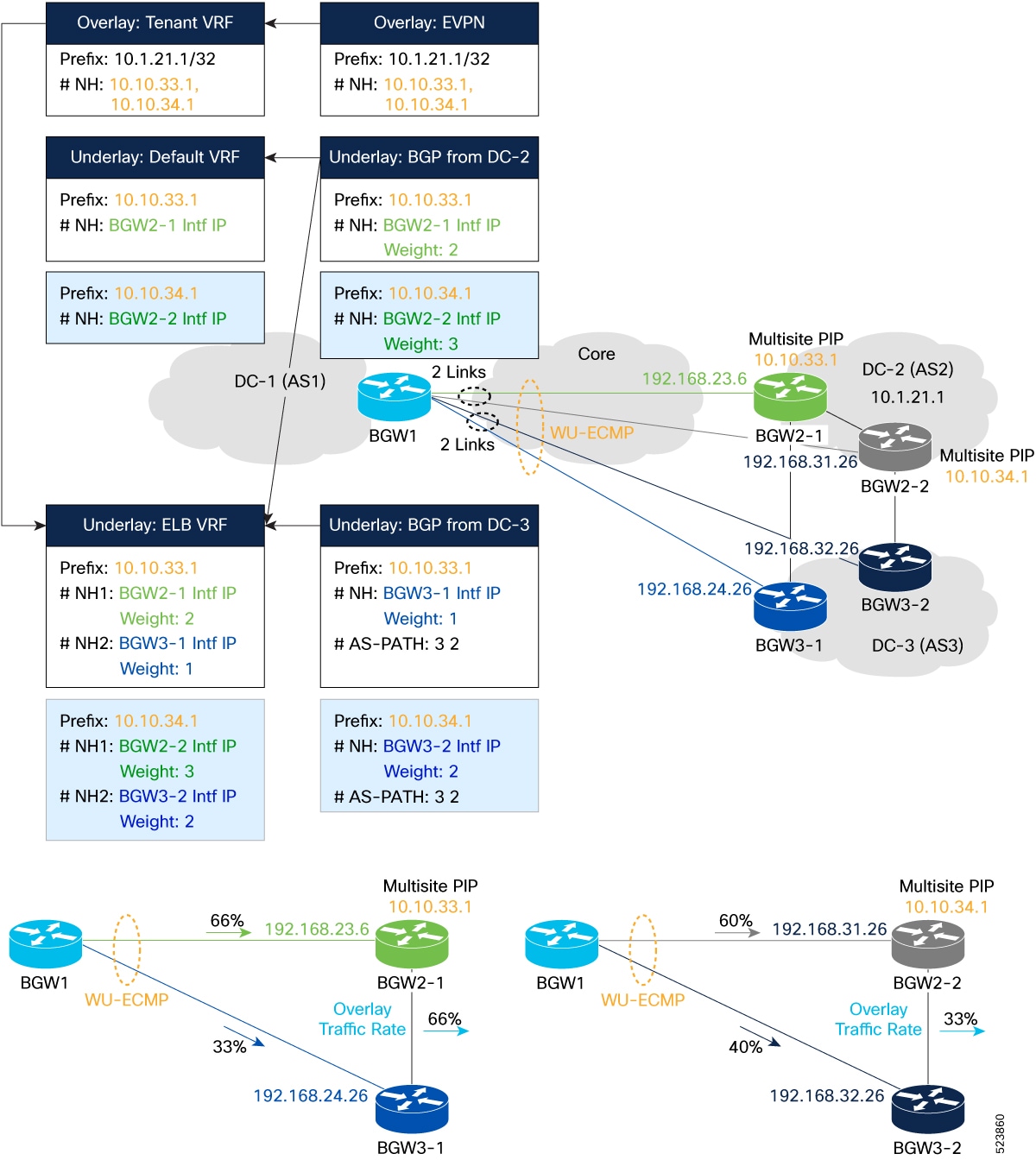
Topology of VXLAN EVPN TE multi-site egress load balancing

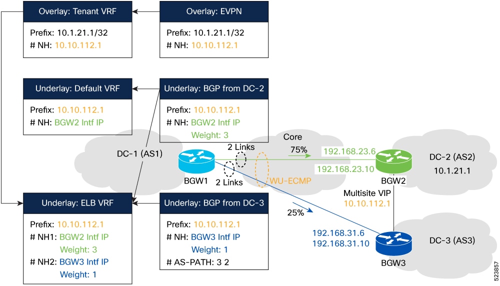
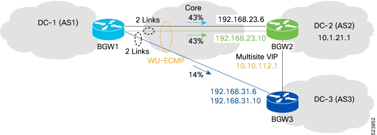
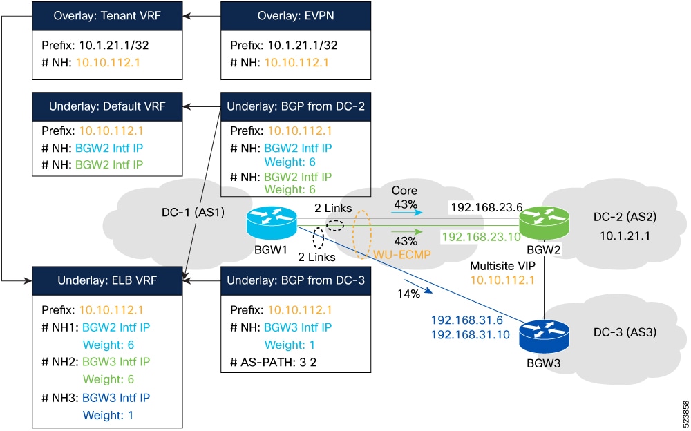
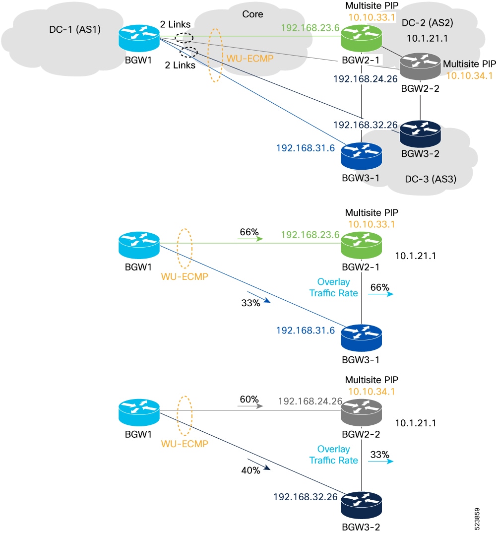
VXLAN EVPN TE multi-site egress load balancing enhances the use of inter-data center links. In this topology, three VXLAN EVPN fabrics in the same multi-site domain connect through a local tier of Border Gateway devices (BGWs) at remote sites.

  • Various BGW types are supported, including Anycast BGWs, vPC BGWs, and Border Gateway Spine devices.

  • Fabrics can interconnect through direct BGW-to-BGW links or through a generic core infrastructure (ISN).

  • Typically, the paths designated in orange serve as the best path or multipath for communication between endpoints at site-1 and site-2.

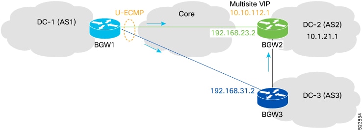
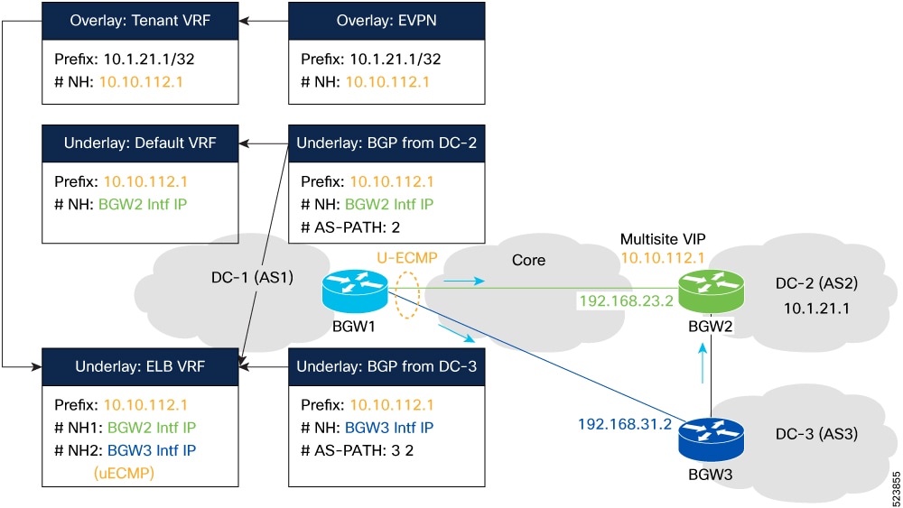
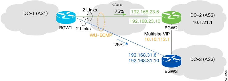
  • Enabling multi-site egress load balancing makes additional traffic distribution paths available beyond the best path, such as routing through an intermediary site (site-3) or generic core infrastructure, as part of unequal ECMP (uECMP) or weighted uECMP (wuECMP).

Figure 1. Topology of VXLAN EVPN TE - Multi-Site egress load balancing

Features and limitations of VXLAN EVPN TE multi-site egress load balancing

VXLAN EVPN TE – Multi-Site egress load-balancing enables optimized network traffic distribution in multi-site VXLAN environments. Support and limitations depend on switch platform and NX-OS release.

Supported platforms and NX-OS releases

  • Beginning with Cisco NX-OS Release 10.4(3)F, the VXLAN EVPN TE - Multi-Site Egress Load-Balancing feature is supported on Cisco Nexus 9300 FX/FX2/FX3/GX/GX2/H2R/H1 switches, and 9700-FX/GX line cards. However, only BGP-based underlay routing is currently supported.

  • Beginning with Cisco NX-OS Release 10.5(2)F, the VXLAN EVPN TE - Multi-Site Egress Load-Balancing feature is supported on Cisco Nexus 9500 Series switches with N9K-X9736C-FX3 line card.

  • The VXLAN EVPN TE - Multi-Site Egress Load-Balancing feature is not supported on Cisco Nexus 9500 modular switches with 9500-FM-E Fabric Modules.

Supported features

  • Load-balancing (LB) of egress traffic across underlay paths that may not be all best paths to remote sites.

  • Explicit and automatic LB policies for associating a specific “weight” (or load) to each multisite path. This comes with the two options of Weighted Equal-Cost Multi-Path (wECMP) and Weighted Unequal Equal-Cost Multipath (wuECMP).

  • BGP-based underlay routing and AS-Path based uECMP path selection.

  • Layer 3 Unicast uECMP/wuECMP in Underlay and Layer 3 (EVPN Type-5) and Layer 2 (EVPN Type-2) Overlay Unicast ECMP/wuECMP.

  • BUM forwarding:

    • BUM traffic will not be subject to egress load-balancing.

    • However, when ingress-replication is used for BUM forwarding across sites (DCI IR), the underlay next-hop path selection can use one among the egress load-balanced paths part of the multipath set and hence can benefit for uECMP in the underlay.

  • Software forwarding: In the baseline case for software forwarding, both Layer 2 and Layer 3 traffic support uECMP/wuECMP on an EVPN VXLAN Multisite setup.

  • CloudSec and Firewall Clustering (PIP next-hop).

  • Downstream VNI. VXLAN OAM, VXLAN Policy-Based Routing (PBR), and External connectivity with VRF lite in a BGW.


    Note


    The dci-advertise-pip command is required on the BGWs to start advertising Type-2 and Type-5 EVPN prefixes with PIP as next-hop (instead than the Multi-Site VIP). In Dynamic weight (wuECMP) in Overlay and Underlay, and with AIGP in Underlay​ section, more information is provided on why it is required to perform wuECMP load-balancing for overlay traffic destined to not equal cost next-hop PIP addresses.


Limitations and unsupported features

  • VXLAN EVPN TE - Multi-Site Egress Load-Balancing does not support the following features:

    • VXLAN with IPv6 Underlay.

    • The hardware profile ecmp resilient configuration with weighted ECMP/uECMP.

    • Multicast overlay traffic.

    • The wuECMP is not supported on Cisco Nexus 9500 Series switches with 9700-FX/FX3 line cards.

  • For a successful downgrade from Cisco NX-OS Release 10.4(3)F to a prior release, ensure that the VXLAN EVPN TE - Multi-Site Egress Load-Balancing configuration has been removed.

Configurations for VXLAN EVPN TE multi-site egress load balancing

VXLAN EVPN TE multi-site egress load balancing requires specific configurations applied on the Border Gateway (BGW) devices. This topic provides an overview of the main configuration types and describes the function of the egress-loadbalance-resolution VRF.

Note


Apply these configurations to the BGW only.


Main configurations

There are three main configurations for VXLAN EVPN TE - Multi-Site egress load balancing:

  • Creation of a Filter Policy: Identifies the remote destination overlay next-hop IP address to which we want to distribute traffic across the underlay path part of the same multipath set. This address could be the common Multi-Site VIP of the remote BGWs or their unique PIPs (when dci-advertise-pip is configured).

  • Creation of a Multipath Policy: Defines the criteria that classify underlay paths as part of a multipath set. This definition enables the provisioning of multiple use cases, such as uECMP and wuECMP with static or dynamic weights. Specifically, in cases where multiple overlay next-hops are present (such as BGWs' PIP addresses), wuECMP can be extended to include the selection of next-hop addresses, creating a “multi-level” load-sharing effect.

  • Enabling Resolution in the ELB VRF: Enables the resolution of underlay paths using the underlay table in egress-loadbalance-resolution- VRF to reach the destination overlay next-hop IP address, rather than using the routing table in the default VRF.

Egress-loadbalance-resolution VRF functions

The egress-loadbalance-resolution- VRF is a new internal VRF that is created automatically by the system. This VRF is not configurable and cannot be deleted. When the ​VXLAN EVPN TE - Multi-Site egress load balancing feature is configured, this new VRF serves to:

  • import and install the underlay protocol (currently BGP only) routes into this table​,

  • perform overlay next-hop resolution in this table instead of the default table, and

  • allow more underlay paths for intersite communication, on top of the best paths installed in the default VRF.

Create an egress load balance filter policy for underlay

Configure an egress load balance filter policy to control which underlay routes, such as specific remote VTEPs, participate in egress load-balancing across multiple underlay paths.

Follow these steps to configure an egress load balance filter policy for underlay:

Before you begin

  • Ensure you have access to the required BGW device with administrative or configuration privileges.

  • Gather the list of next-hop IP addresses or BGP communities that identify the underlay routes to be filtered.

  • Confirm that BGP is enabled and configured on the device.

Procedure


Step 1

Enter global configuration mode.

Example:

switch# config terminal
switch(config)#

Step 2

Define a prefix list to match the remote next-hops.

Example:

switch# config terminal
switch(config)# ip prefix-list remote_nexthop seq 5 permit 10.10.112.1/32 

Step 3

Create a route map.

Example:

switch(config)# route-map ROUTE_MAP_1
\switch(config-route-map)#

The egress load balance logic applies only to VTEP routes or next-hops specified in the filter policy using a route map.

Step 4

Match the underlay routes in the route map using one of these methods:

  • To match routes by prefix list:
    switch(config-route-map)# match ip address prefix-list remote_nexthop

    OR

  • To match routes by community:
    switch(config-route-map)# match community BGPCommunity

Step 5

Exit route map configuration mode.

Example:

switch(config-route-map)# exit
switch(config)#

Step 6

Enter BGP router configuration mode.

Example:

switch(config)# router bgp 65001
switch(config-router)#

Step 7

Configure the IPv4 unicast address family.

Example:

switch(config-router)# address-family ipv4 unicast
switch(config-router-af)#

Step 8

Apply the egress load balance filter policy using the route map.

Example:

switch(config-router-af)# load-balance egress filter-policy route-map ROUTE_MAP_1

You can tag the underlay routes with either a community attribute or a prefix-list. Use the command in the no form to remove the filter policy.

Note

 
  • When filtered by community, the advertising egress BGW must tag all paths for a given route with the same community.

  • Ensure that you configure the filter policy so that the system can compute ELB's paths for the prefixes.


The BGW device restricts egress load-balancing to only those VTEP routes or next-hops specified by your filter policy, optimizing traffic flow according to your network requirements.

Create an egress load-balancing auto-multipath policy for underlay

You can configure an auto-multipath policy using a route-map that specifies the maximum number of underlay paths to be computed and the criteria for assigning those underlay paths to the same multi-path sets. This policy can match one or more configured thresholds, such as AIGP metric or AS-Path difference, when compared to the best path. In the absence of an auto-multipath policy, only the best path is installed.

Follow these steps to configure an egress load-balancing auto-multipath policy for the underlay:

Before you begin

  • Ensure you have access to the device CLI with the necessary privileges.

  • Determine prefix-list names, route-map names, and threshold values for metrics or path length differences.

Procedure


Step 1

Enter global configuration mode.

Example:

switch# config terminal
switch(config)#

Step 2

(If not already created) Define a prefix list to match remote next-hop addresses.

Example:

switch(config)# ip prefix-list remote_nexthop seq 5 permit 10.10.112.1/32 

Step 3

Create or edit a route-map for grouping underlay paths and setting multipath policy.

Example:

switch(config-route-map)# route-map ROUTE_MAP_2

This route-map is to group underlay paths as part of the same multipath set even if they are unequal (and inferior) to the best path. This can be done based on the configured difference of AIGP-metric or AS-Path length for those underlay paths when compared to these values for the best-path.

Note


Use the 'match' and 'set' commands to configure the system according to the specified requirements.

The egress load-balance automatic multipath policies can be enabled as below:

  1. Set the maximum number of multipaths to install (range: 1–64):

    Example:

    switch(config-route-map)# set maximum-paths 5

    Configures the maximum number of multipath to be computed and installed for egress load-balancing. The range is 1–64.

  2. (Optional) Set criteria for unequal-cost multipath selection:

    Example:

    For AS-path length difference (Range:1–255)
    switch(config-route-map)# set as-path-length difference 5
    For IGP metric difference (Range: 1–65535)
    switch(config-route-map)# set metric difference 100
    For AIGP metric difference (Range:1–4294967295)
    switch(config-route-map)# set aigp-metric difference 100

    Configures the difference in AS-Path-length or metric value or AIGP metric value compared to the best path that underlay paths must have to be considered for unequal cost load balance.

  3. (Optional) Configure relative load-share for equal or unequal multipath groups

    Example:

    switch(config-route-map)# set load-share multipath-equal-group 100
    OR
    switch(config-route-map)# set load-share multipath-unequal-group 100

    Configures the relative load-share weights for auto multipath groups (equal and unequal). The range is 1–255.

    Use the no form of this command to remove the load share configuration in the route map.

    Note


    It is sufficient to define a 'multipath-equal-group weight' to include both the 'best-path' and its equal-cost multipaths.

  4. (Optional) Match route attributes or apply community tags as needed.

Step 4

Exit route-map configuration.

Example:

switch(config-route-map)# exit
switch(config)#

Step 5

Enter BGP configuration mode and specify the address family.

Example:

switch(config)# router bgp 65001
switch(config-router)# address-family ipv4 unicast
switch(config-router-af)#

Step 6

Apply the auto-multipath policy using the configured route-map.

Example:

switch(config-router-af)# load-balance egress multipath auto-policy route-map ROUTE_MAP_2

Configures the parameters to control automatic multipath selection and load-sharing in BGP.

Use the no form of this command to remove the parameters configuration.

In the absence of the auto multipath policy only the best-path is installed.

Note


If a community match is used to select the prefix, all paths for this prefix should be tagged with the same community by the advertising egress BGW, which can be done by tagging the prefix during origination into BGP.


BGP installs multiple underlay paths for egress load balancing in accordance with the defined policy, increasing bandwidth utilization and path redundancy

Options for assigning weights to underlay paths

To improve the distribution of overlay traffic flows across multiple underlay paths, you can assign static weights to these paths using two methods:

  • Assign a static weight to all best-path underlay routes and a different weight to all unequal, inferior underlay paths included in the same multipath set. These unequal paths must meet criteria such as AS-path length or AIGP metric.

  • Assign a static weight explicitly to a specific underlay path for targeted load balancing.

Both methods enable you to customize how overlay traffic is balanced across available underlay routes, allowing for more precise control over network resource usage.

Calculation of load share weights for BGP multipath groups

BGP derives load share weights using the Load Share Weight Calculation (LSWC) when auto-multipath policies configure either or both of the following commands:

  • set load-share multipath-equal-group

  • set load-share multipath-unequal-group

Multipath groups
  • A multipath-equal-group is a set of underlay paths that are equivalent to the best path based on AS-Path length.

  • A multipath-unequal-group includes underlay paths that do not match the best path’s quality but fall within a configured difference threshold for AS-Path length.

Example-1:

When the as-path length difference is set to 4, BGP uses LSWC to assign weights and includes unequal underlay paths in the multipath-unequal-group if their AS-Path length falls within the configured difference:

route-map auto-multipath  permit 10
  match ip address prefix-list site_A_BGW2 
  set as-path length difference 4
  set maximum-paths 64 
  set load-share multipath-equal-group 40 
  set load-share multipath-unequal-group 60

Example-2:

When the aigp-metric difference is set to 10, BGP adds unequal underlay paths to the multipath-unequal-group if their AIGP metric is within the configured difference compared to the best path:

route-map auto-multipath  permit 10
  match ip address prefix-list site_A_BGW2               
  set aigp-metric difference 10
  set maximum-paths 64
  set load-share multipath-equal-group 40 
  set load-share multipath-unequal-group 60

Note


If only one of the multipath group commands (set load-share multipath-equal-group or set load-share multipath-unequal-group) is explicitly configured, BGP implicitly assigns the other group a value of 1.


Configure explicit load share weights for egress paths

Configure explicit load share weights in BGP to override auto-multipath behavior for selected routes and next-hops, enabling precise traffic distribution.

Key characteristics of this configurations are:

  • Explicit load-share route-map entries precede auto-multipath route-map entries in processing.

  • An auto-multipath rule may or may not be present with explicit load-share rules.

  • A maximum of 64 explicit path entries are allowed per destination IP, independent of the maximum path attribute in auto-multipath.

  • Paths matched by explicit load-share rules are excluded from auto-multipath processing for that destination; this can include paths that do not qualify as ECMP or uECMP.

  • If an explicit rule matches the "best path" for a destination, the multipath-equal-group may have zero paths if no other ECMP paths qualify.

  • Load-share values and path weights for explicit paths are proportional to and calculated similarly to ECMP or uECMP load-share values specified in auto-multipath, if present.

  • If only explicit load-share paths are defined (no auto-multipath), the configured values are used directly as weights.

  • If no explicit load-share value is specified for a policy, there is no default and the policy has no effect.

  • The "best path" always receives a weight and is downloaded to URIB. If neither explicit nor auto-multipath policies apply, the best path receives a default weight of 1.

Use this task to assign explicit weights to egress paths for destination prefixes and next-hops, enabling granular control over traffic distribution in your BGP network.

Before you begin

Before you begin, ensure:

  • You have configuration access to BGP on your device.

  • The sets of destination IPs and next-hops to match are already identified.

Procedure

Step 1

Enter global configuration mode.

Example:
switch# config terminal
switch(config)#

Step 2

Enter BGP router configuration mode.

Example:
switch(config)# router bgp 100
switch(config-router)#

Step 3

Create or access the required route-map for explicit load-share.

Example:
switch(config)# route-map load_distribute permit 6

Step 4

Match the destination prefixes using a prefix list.

Example:
switch(config-route-map)# match ip address prefix-list <match_prefix>

Step 5

Match specific next-hops using a prefix list.

Example:
switch(config-route-map)# match ip next-hop prefix-list <next-hop_prefix>

Step 6

Set the explicit load-share weight for each matched path.

Example:
switch(config-route-map)# set load-share <weight-value>

If only explicit load-share paths are defined, the specified values are used directly as weights. If no load-share value is configured, the policy does not affect path selection.


Explicit load-share weights are applied to egress paths, so BGP traffic is distributed according to your configuration.

Example 1: If set load-share is configured within an auto-multipath route-map and contains LSWC multipath-group commands, the explicit load-share is applied:


        route-map auto-multipath permit 6
        match ip address prefix-list match_ip 
        match ip next-hop prefix-list path1
        set load-share 100
        
        route-map auto-multipath permit 10
        match ip address prefix-list site_A_BGW2 
        set as-path-length difference 4 
        set aigp-metric difference 100
        set maximum-paths 64 
        set load-share multipath-equal-group 40
        set load-share multipath-unequal-group 60
      

Example 2: If no LSWC multipath-group is present, BGP uses standard auto-multipath weight calculation and ignores the explicit load-share.


        route-map auto-multipath permit 6
        match ip address prefix-list match_ip 
        match ip next-hop prefix-list path1
        set load-share 100
        
        route-map auto-multipath permit 10
        match ip address prefix-list site_A_BGW2 
        set as-path-length difference 4 
        set aigp-metric difference 100
        set maximum-paths 64
      

Enable egress load-balancing for overlay

Enable egress load-balancing for overlay EVPN prefixes, allowing next-hop resolution using the egress-loadbalance-resolution-VRF in the underlay.

Use this task when deploying EVPN overlays in multisite scenarios to optimize next-hop selection across IPv4 and IPv6 tables. Ensure underlay egress load-balance computation is already enabled.

Before you begin

  • Ensure BGP is configured on the device.

  • Egress load-balance computation must be enabled in the underlay table before configuring overlay.

Procedure


Step 1

Enter global configuration mode.

Example:

switch# config terminal
switch(config)#

Step 2

Enter BGP router configuration mode.

Example:

switch(config)# router bgp 100
switch(config-router)#

Step 3

Configure the L2EVPN address family.

Example:

switch(config-router)# address-family l2vpn evpn
switch((config-router-af)#

Step 4

Enable egress load-balancing for overlay multisite.

Example:

switch(config-router-af)# nexthop load-balance egress multisite

This command enables overlay EVPN next-hop resolution using the egress-loadbalance-resolution-VRF IPv4 or IPv6 table.

To remove the configuration, use no nexthop load-balance egress multisite.

The multisite option restricts the functionality to EVPN next-hops learned from multisite networks and applies to Type-2 and Type-5 routes imported into VRFs.

Note


Enable this configuration only after you have enabled egress-load-balance computation in the underlay table.


EVPN overlay prefixes now use the underlay's egress-loadbalance-resolution-VRF for next-hop resolution. Load-balancing is enabled in multisite environments.

Enable uECMP or wuECMP load balancing for overlay

Configure the device to distribute traffic unequally or with assigned weights among multiple overlay next-hops, improving routing efficiency and performance in BGP EVPN environments.

This procedure allows you to optimize overlay routing where next-hops have non-equal IGP metrics.


Note


Do not use this feature with VIP next-hops, as they are unsupported.


Before you begin

Ensure:

  • BGP is enabled and accessible on the device.

  • You have administrator access to the CLI.

Procedure


Step 1

Enter global configuration mode.

Example:

switch# config terminal
switch(config)#

Step 2

Enter BGP router configuration mode with your AS number.

Example:

switch(config)# router bgp 100
switch(config-router)#

Step 3

Access the EVPN address family configuration.

Example:

switch(config-router)# address-family l2vpn evpn
switch((config-router-af)#

Step 4

Enable overlay (EVPN) next-hop resolution with egress load balancing. For details, see the documentation for egress-loadbalance-resolution-VRF tables.

Example:

switch(config-router-af)# nexthop load-balance egress multisite

Enables overlay (EVPN) next-hop resolution using the corresponding IPv4 or IPv6 table in egress-loadbalance-resolution- VRF's. For more information on egress-loadbalance-resolution- VRF's table, see Configurations for VXLAN EVPN TE multi-site egress load balancing

Step 5

Configure the maximum number of paths for egress load balancing.

Example:

switch(config-router-af)# maximum-path 64

Use no maximum-path to remove the setting.

Note


If the specified value is greater than 1, and you also configure maximum-paths unequal-cost , wuECMP will be enabled and weights assigned based on next-hop metrics.

Step 6

Enable unequal cost multipath in the overlay.

Example:

switch(config-router-af)# maximum-paths unequal-cost

Use no maximum-paths unequal-cost to disable it.

Note

 
  • If both nexthop load-balance egress multisite , maximum-path , and maximum-paths unequal-cost are configured and there are multiple overlay next-hops with different IGP metrics, weighting is applied and the egress-loadbalance-resolution-VRF table is used.

  • If nexthop load-balance egress multisite is not configured, but maximum-path and maximum-paths unequal-cost are, weighting is still applied based on IGP metrics and the default table is used.

Step 7

Exit address-family configuration mode.

Example:

switch(config-router-af)# exit
switch(config-router)#

Step 8

(Optional) Ignore IGP metric for overlay next-hops.

Example:

switch(config-router)# bestpath igp-metric ignore

If this is set, ECMP (not weighted) will be used even if maximum-paths unequal-cost is configured. Use no bestpath igp-metric ignore to disable.


The device is now configured for unequal cost or weighted ECMP across overlay next-hops.

Commands for VXLAN EVPN TE multi-site egress load balancing

These commands provide information and troubleshooting details for VXLAN EVPN TE - Multi-site egress load-balancing on NX-OS platforms:

Table 1. VXLAN EVPN TE multi-site egress load balancing command reference

Command

Purpose

show ip|ipv6 route [detail] vrf egress-loadbalance-resolution-

Displays a special internal VRF that is automatically created. This VRF will be implicitly used internally when the egress load-balance configuration is enabled under BGP.

When BGP is configured with an ELB filter-policy and an auto-multipath policy, it will inherit the best path for a route from the default table and will include additional ELB paths based on the ELB policy.

When the detail option is enabled, it will display the weight that BGP sends to the RIB, if wuECMP is configured.

Note


Beginning with Cisco NX-OS Release 10.4(3)F, the table id for the egress-loadbalance-resolution- VRF will be statically allocated with a value of 4089/0x0ff9 and will be outside the "limit-resource vrf" pool of allocation. It will not impact any existing user configuration.

show ip|ipv6 route [detail] vrf tenant_vrf

Displays the overlay prefix in an EVPN-VXLAN tenant VRF where the nexthop is resolved via egress-loadbalance-resolution- table instead of default table.

When the detail option is enabled, it will display the weight assigned to the next-hop that is sent from BGP to RIB, if wuECMP is configured.

show bgp ipv4 unicast ipaddress vrf egress-loadbalance-resolution-

Displays the underlay BGP routes and next-hops, including the derived AIGP metric if AIGP is configured in the underlay. For wuECMP cases, it shows the weight, which is derived dynamically (i.e., from the AIGP metric or from a statically configured load-share-weight). In the case of uECMP or ECMP, there will be no weight displayed.

show l2route evpn mac all detail

Displays the next-hops with weight for the mac routes, if wuECMP is configured.

show l2route evpn ead es detail

Displays the weight associated with the next-hops for the EAD/ES route if wuECMP is configured.

Supported load balancing scenarios in VXLAN EVPN TE Multi-Site

The VXLAN EVPN TE Multi-Site feature supports various egress load balancing modes to address deployment requirements and optimize traffic engineering. The following scenarios are available

Supported load balancing scenarios

  • uECMP in the underlay and single EVPN next-hop for overlay prefixes.

    Uses underlay Equal Cost Multi-Path routing (uECMP) for distributing traffic at the network fabric level, while overlay prefixes resolve to a single next-hop via EVPN.
  • Static wuECMP with load-share, explicit load-share in the underlay, and single EVPN next-hop for overlay prefixes.

    Configures static weight values for ECMP paths in the underlay, enabling tailored traffic distribution. Overlay traffic is sent to a single EVPN next-hop.
  • Dynamic weight (wuECMP) in overlay and underlay and with AIGP in underlay.

    Applies dynamic weighting based on overlay and underlay path metrics, utilizing AIGP (Accumulated IGP) in the underlay to influence path selection.

uECMP in Underlay, single EVPN next-hop for Overlay prefixes

As highlighted in the figure below, in this use case all the overlay prefixes advertised from DC-2 toward DC-1 have a single EVPN next-hop represented by the Multi-Site VIP address shared by all the BGW devices in DC-2 (only one device, BGW2, is shown for simplicity in the figure).

Underlay reachability from the BGW1 device in DC-1 to the Multi-Site VIP in DC-2 is possible using the following two underlay paths:

  1. Green path: The best path connecting BGW1 to BGW2

  2. Blue path: The less favorable path going through BGW3 in DC-3 (alternatively, the suboptimal blue path could go through one or more router devices part of the Core infrastructure).

The goal in this use case is to ensure that both the green and blue underlay paths can be equally used for any overlay communication between DC-1 and DC2. For this to be possible, the two paths must be considered as uECMP paths part of a same multipath set and the configuration steps below applied to the BGW1 device in DC-1 achieve this purpose.

Enable VXLAN EVPN TE - Multi-Site Egress Load-Balancing uECMP in Underlay

All the commands below must be configured on the BGW1 device in DC-1.

  1. Create a Filter-policy.

    • Specify the underlay routes to enable ELB uECMP. In this case, the underlay route is the Multi-Site VIP address in DC-2 representing the next-hop for the overlay prefixes advertised to DC-1.
      ip prefix-list site2_ms_vip seq 5 permit 10.10.112.1/32​
      
    • Create a route-map and apply the previously configured prefix-list in the match condition.

      route-map Filter-Policy permit 10​
        match ip address prefix-list site2_ms_vip​
      
  2. Enable ELB Filter-policy (under the IPv4 or IPv4 BGP address-family).
    router bgp 1​
      address-family ipv4 unicast​
        load-balance egress filter-policy route-map Filter-Policy
  3. Verify the installation of DC-2 Multi-Site VIP route in the Egress-loadbalance-resolution- VRF table. At this point, only the green best-path is considered to reach the destination.
    BGW1# show ip route 10.10.112.1 vrf egress-loadbalance-resolution-​
    ​
    10.10.112.1/32, ubest/mbest: 1/0​
      *via 192.168.23.2%default, [20/0], 16:36:15, bgp-1, external, tag 2, uecmp​ ! Green path
  4. Create a Multipath Auto-policy​.

    • Provide the criteria to assign unequal underlay paths to the multipath set together with the best path. Differences in BGP attributes, such as AS-Path length, can be considered to group unequal underlay paths as part of the same multipath set.

    • Specify the maximum number of underlay paths part of the multipath set to be computed and installed for ‘Egress Load Balancing’.

    route-map Auto-Policy permit 10​
      set as-path-length difference 1 <1 to 255>​
      set maximum-paths 2 <1 to 64>
  5. Enable the ELB Multipath Auto-policy under the IPv4 or IPv6 BGP address-family.
    router bgp 1​
      address-family ipv4 unicast​
        load-balance egress multipath auto-policy route-map Auto-Policy
  6. Verify routes in Egress-loadbalance-resolution VRF table of URIB. The blue suboptimal path has been added to the green best-path as a viable option to reach the Multi-Site VIP address in DC-2.
    BGW1# show ip route 10.10.112.1 vrf egress-loadbalance-resolution-​
    ​
    10.10.112.1/32, ubest/mbest: 2/0​
      *via 192.168.23.2%default, [20/0], 00:44:17, bgp-1, external, tag 2, uecmp ! Green path​
      *via 192.168.31.2%default, [20/0], 00:44:17, bgp-1, external, tag 3, uecmp ! Blue path

Enabling Resolution in the ELB VRF for uECMP in Overlay

  1. Enable Overlay Next-hop Resolution using the Egress Load Balancing uECMP Underlay Paths.

    • This command enables resolution of EVPN next-hops using the Egress-loadbalance-resolution- VRF table. Therefore, both underlay paths (the green and the unequal blue one) would be used for equal cost load-balancing of intersite traffic.

    • This command must be enabled under the BGP L2VPN EVPN address-family after enabling the Egress Load Balancing computation in the underlay table.

    router bgp 1​
      address-family l2vpn evpn​
        nexthop load-balance egress multisite
  2. Verify overlay routes in Tenant VRF table. As shown below, reachability to an overlay prefix in DC-2 from the BGW1 device in DC-1 is through the DC-2 Multi-Site VIP address (10.10.112.1) and the lookup for that is to be performed in the egress-loadbalance-resolution- VRF. As a result, traffic will be distributed evenly across the two installed underlay paths. (as shown above).
    BGW1# show ip route 10.1.21.1 vrf 3001​
    ​
    10.1.21.1/32, ubest/mbest: 1/0​
      *via 10.10.112.1%egress-loadbalance-resolution-, [20/2000], 04:43:40, bgp-1, external, tag 2, ​
      eLB, segid: 3003001 tunnelid: 0x67027001 encap: VXLAN​
    

uECMP Routing details

This section provides more detailed troubleshooting information for the uECMP in Underlay, single EVPN next-hop for Overlay prefixes use case.

  1. Underlay Route Programming

    The DC-2 Multi-Site VIP routereceived from remote BGWs via uECMP underlay paths is programmed on the BGW1 device in DC-1 into the BGP routing table and unicast routing table for the egress-loadbalance-resolution- VRF.

    The following example shows the sample output for the following components:

    • BGP - uECMP: Note how the second path is labeled as multipath uecmp, since the AS-Path difference is 1, matching the previously defined criteria to considered underlay paths part of the same multi-path set.
      BGW1# show bgp ipv4 unicast 10.10.112.1 vrf egress-loadbalance-resolution-​
      <Truncated>​
        Advertised path-id 1​
        Path type: external, path is valid, is best path, no labeled nexthop, in rib​
                   Imported from 10.10.112.1/32 (VRF default)​
        AS-Path: 2 , path sourced external to AS​
          192.168.23.2 (metric 0) from 192.168.23.2 (101.2.33.1)​
            Origin incomplete, MED 0, localpref 100, weight 0​
      ​
        Path type: external, path is valid, not best reason: newer EBGP path, multipath, uecmp, no labeled nexthop, in rib​
                   Imported from 10.10.112.1/32 (VRF default)​
        AS-Path: 3 2 , path sourced external to AS​
          192.168.31.2 (metric 0) from 192.168.31.2 (101.3.33.1)​
            Origin incomplete, MED not set, localpref 100, weight 0​
    • URIB - uECMP: The following example shows how the two uECMP paths equally leveraged to reach DC-2 Multi-Site VIP destination.
      BGW1# show ip route 10.10.112.1 vrf egress-loadbalance-resolution-​
      <Truncated>​
      10.10.112.1/32, ubest/mbest: 2/0​
          *via 192.168.23.2%default, [20/0], 17:58:44, bgp-1, external, tag 2, uecmp​ ! Green path​
          *via 192.168.31.2%default, [20/0], 17:58:44, bgp-1, external, tag 3, uecmp ! Green path​​
    • FIB - uECMP:
      BGW1# show forwarding route 10.10.112.1 vrf egress-loadbalance-resolution-​
      <Truncated>​
      ------------------+---------------------+----------------+-----------------+----------------​
      Prefix            | Next-hop            | Interface      | Labels          | Partial Install​
      ------------------+---------------------+----------------+-----------------+----------------​
      *10.10.112.1/32      192.168.23.2            Ethernet1/6​
                           192.168.31.2            Ethernet1/7​
  2. Overlay Route Programming

    The egress-loadbalance-resolution- VRF will be used to resolve the remote VIP next-hops associated to the received overlay routes.​

    The following example shows the sample output for following components:

    • BGP:
      BGW1# show bgp l2vpn evpn 10.1.21.1​
      <Truncated>​
        Advertised path-id 1​
        Path type: external, path is valid, is best path, no labeled nexthop, has esi_gw​
                   Imported to 3 destination(s)​
                   Imported paths list: 3001 L3-3003001 L2-2001001​
        AS-Path: 2 , path sourced external to AS​
          10.10.112.1 (metric 0) from 101.2.33.1 (101.2.33.1)​
            Origin IGP, MED 2000, localpref 100, weight 0​
            Received label 2001001 3003001​
            Extcommunity: RT:1:2001001 RT:1:3003001 SOO:102.2.121.1:0
    • URIB:
      BGW1# show ip route 10.1.21.1 vrf 3001​
      <Truncated>​
      10.1.21.1/32, ubest/mbest: 1/0​
          *via 10.10.112.1%egress-loadbalance-resolution-, [20/2000], 00:28:03, bgp-1, external, ​
          tag 2, eLB, segid: 3003001 tunnelid: 0x67027001 encap: VXLAN​
    • FIB:
      BGW1# show forwarding route 10.1.21.1 vrf 3001​
      <Truncated>​
      ------------------+---------------------+----------------+-----------------+----------------​
      Prefix            | Next-hop            | Interface      | Labels          | Partial Install​
      ------------------+---------------------+----------------+-----------------+----------------​
      10.1.21.1/32         10.10.112.1           nve1​
      BGW1# show forwarding route 10.10.112.1 vrf egress-loadbalance-resolution-​
      <Truncated>​
      ------------------+---------------------+----------------+-----------------+----------------​
      Prefix            | Next-hop            | Interface      | Labels          | Partial Install​
      ------------------+---------------------+----------------+-----------------+----------------​
      *10.10.112.1/32      192.168.23.2            Ethernet1/6​
                           192.168.31.2            Ethernet1/7​

Static wuECMP with Load-Share and Explicit load-share in Underlay, and single EVPN next-hop for Overlay Prefixes

Enable VXLAN EVPN TE - Multi-Site Egress Load-Balancing Static wuECMP with Load-Share in Underlay

As highlighted in the figure below, also in this use case all the overlay prefixes advertised from DC-2 toward DC-1 have a single EVPN next-hop represented by the Multi-Site VIP address shared by all the BGW devices in DC-2. Underlay reachability from the BGW1 device in DC-1 to the Multi-Site VIP in DC-2 is possible via four underlay paths: two green ECMP best-paths connecting BGW1 to BGW2 and two less favorable underlay paths going through BGW3 in DC-3 (alternatively, the suboptimal blue paths could go through one or more router devices part of the Core infrastructure).

The goal in this use case is to ensure that both green and blue underlay paths can be used for overlay communication between DC-1 and DC2, but with a different traffic load-share (75% of the traffic should use the green paths and only 25% the blue paths). The configuration steps below applied to the BGW1 device in DC-1 achieve this purpose.

  1. Create a Filter-policy.

    • Specify the underlay routes to enable ELB wuECMP. In this case, the underlay route is the Multi-Site VIP address in DC-2 representing the next-hop for the overlay prefixes advertised to DC-1.
      ip prefix-list site2_ms_vip seq 5 permit 10.10.112.1/32​
      
    • Create a route-map and apply the previously configured prefix-list in the match condition.

      route-map Filter-Policy permit 10​
        match ip address prefix-list site2_ms_vip​
      
  2. Enable ELB Filter-policy (under the IPv4 or IPv4 BGP address-family).
    router bgp 1​
      address-family ipv4 unicast​
        load-balance egress filter-policy route-map Filter-Policy
  3. Verify routes in Egress-loadbalance-resolution- VRF table. By default, only the two green ECMP underlay paths are installed to reach the Multi-Site VIP address in DC-2.
    BGW1# show ip route 10.10.112.1 vrf egress-loadbalance-resolution-​
    ​
    10.10.112.1/32, ubest/mbest: 1/0​
      *via 192.168.23.6%default, [20/0], 16:36:15, bgp-1, external, tag 2, uecmp ! Green Path
      *via 192.168.23.10%default, [20/0], 16:37:41, bgp-1, external, tag 2, uecmp ! Green Path 
    
  4. Create a Multipath Auto-policy​. For more information, see Calculation of load share weights for BGP multipath groups.

    • Provide differences in BGP attributes such as AS-Path length that can be considered to group underlay paths as part of the same multipath set.

    • Specify the maximum number of multipaths to be computed and installed for ‘Egress Load Balance’. In this case, the value is 4 (two green and two blue paths).

    • Specify the Load-Share Weight to be associated to the ECMP Path-set and uECMP Path-set of underlay paths. The goal, as shown in the figure above, is to send 75% of the traffic on the green best path underlay links and 25% on the blue unequal underlay links.

      route-map Auto-Policy permit 10​
        set as-path-length difference 1 <1 to 255>​
        set maximum-paths 4 <1 to 64>​
        set load-share multipath-equal-group 3 <1 to 255>​
        set load-share multipath-unequal-group 1 <1 to 255>
  5. Enable ELB Multipath Auto-policy​ under the IPv4 or IPv6 BGP address-family.
    router bgp 1​
      address-family ipv4 unicast​
        load-balance egress multipath auto-policy route-map Auto-policy
  6. Verify wuECMP with load-share routes in Egress-loadbalance-resolution VRF table of URIB. The blue suboptimal paths have been added to the green best-paths as viable options to reach the Multi-Site VIP address in DC-2, but with a different weight (1).
    BGW1# show ip route 10.10.112.1 detail vrf egress-loadbalance-resolution-​
    ​
    10.10.112.1/32, ubest/mbest: 4/0​
        *via 192.168.23.6%default, [20/0], 1w0d, bgp-1, weight:3, external, tag 2, uecmp ! Green Path​
        *via 192.168.23.10%default, [20/0], 1w0d, bgp-1, weight:3, external, tag 2, uecmp ! Green Path​
        *via 192.168.31.6%default, [20/0], 1w0d, bgp-1, weight:1, external, tag 3, uecmp ! Blue Path​
        *via 192.168.31.10%default, [20/0], 1w0d, bgp-1, weight:1, external, tag 3, uecmp ! Blue Path​

    Because of the automatic load-share configuration applied to ECMP and uECMP paths, the two green path has been assigned a total weight of 3 (1.5 each), whereas the two blue paths has a total weight of 1 (0.5 each). Consequently, 75% of the overlay traffic from DC-1 to DC-2 is routed through the green paths, while the remaining 25% traverses the blue paths:

    Green paths: (3 + 3) / (3+3+1+1) = 0.75

    Blue paths: (1 + 1) / (3+3+0.5+0.5) = 0.25

Static wuECMP with Load-Share Routing details

  1. Underlay Route Programming

    The DC-2 Multi-Site VIP route received from remote BGWs via uECMP underlay paths is programmed on the BGW1 device in DC-1 into the BGP routing table and unicast routing table for the egress-loadbalance-resolution- VRF.

    The following example shows the sample output for following components:

    • BGP: Note how the second path is labeled as “multipath uecmp” even if it is actually an ECMP path with the first best-path one. The other two paths are proper “multipath uecmp”, since the AS-Path difference is 1, matching the previously defined criteria to considered underlay paths part of the same multi-path set. Additionally, a 3:1 weight ratio is applied to the two sets of paths because of the load-share configuration.
      BGW1# show bgp ipv4 unicast 10.10.112.1 vrf egress-loadbalance-resolution-​
      <Truncated>​
        Advertised path-id 1​
        Path type: external, path is valid, is best path, no labeled nexthop, in rib​
                   Imported from 10.10.112.1/32 (VRF default)​
        AS-Path: 2 , path sourced external to AS​
          192.168.23.6 (metric 0) from 192.168.23.6 (101.2.33.1)​
            Origin incomplete, MED 0, localpref 100, weight 0, load share weight 3​
      
        Path type: external, path is valid, not best reason: newer EBGP path, multipath, no labeled nexthop, in rib​
                   Imported from 10.10.112.1/32 (VRF default)​
        AS-Path: 2 , path sourced external to AS​
          192.168.23.10 (metric 0) from 192.168.23.10 (101.2.33.1)​
            Origin incomplete, MED 0, localpref 100, weight 0, load share weight 3​
      ​  Path type: external, path is valid, not best reason: newer EBGP path, multipath, uecmp, no labeled nexthop, in rib​
                   Imported from 10.10.112.1/32 (VRF default)​
        AS-Path: 3 2 , path sourced external to AS​
          192.168.31.6 (metric 0) from 192.168.31.6 (101.3.33.1)​
           Origin incomplete, MED not set, localpref 100, weight 0, load share weight 1​
      
        Path type: external, path is valid, not best reason: newer EBGP path, multipath, uecmp, no labeled nexthop, in rib​
                   Imported from 10.10.112.1/32 (VRF default)​
        AS-Path: 3 2 , path sourced external to AS​
          192.168.31.10 (metric 0) from 192.168.31.10 (101.3.33.1)​
            Origin incomplete, MED not set, localpref 100, weight 0, load share weight 1
    • URIB:
      BGW1# show ip route 10.10.112.1 detail vrf egress-loadbalance-resolution-​
      <Truncated>​
      10.10.112.1/32, ubest/mbest: 4/0​
          *via 192.168.23.6%default, [20/0], 1w0d, bgp-1, weight:3, external, tag 2, uecmp ! Green Path​
      <Truncated>​
          *via 192.168.23.10%default, [20/0], 1w0d, bgp-1, weight:3, external, tag 2, uecmp ! Green Path​
      <Truncated>​
          *via 192.168.31.6%default, [20/0], 1w0d, bgp-1, weight:1, external, tag 3, uecmp ! Blue Path​​
      <Truncated>​
          *via 192.168.31.10%default, [20/0], 1w0d, bgp-1, weight:1, external, tag 3, uecmp ! Blue Path​​
      <Truncated>​
      ​
    • FIB:
      BGW1# show forwarding route 10.10.112.1 vrf egress-loadbalance-resolution-​
      <Truncated>​
      ------------------+---------------------+----------------+-----------------+----------------​
      Prefix            | Next-hop            | Interface      | Labels          | Partial Install​
      ------------------+---------------------+----------------+-----------------+----------------​
      *10.10.112.1/32      192.168.23.6            Ethernet1/22 >> 24 Entries​
                           192.168.23.6            Ethernet1/22 ​
                           ..... ​
                           192.168.23.10           Ethernet1/23 >> 24 Entries​
                           192.168.23.10           Ethernet1/23​
                           ..... ​
                           192.168.31.6            Ethernet1/32 >> 8 Entries​
                           192.168.31.6            Ethernet1/33​
                           ..... ​
                           192.168.31.10           Ethernet1/32 >> 8 Entries​
                           192.168.31.10           Ethernet1/33​
                           ..... 

      The following summarizes the FIB forwarding entries created based on weight of ECMP (3) and uECMP (1) path sets:

      • ECMP Path-Set: 48 Entries​

      • uECMP Path-Set: 16 Entries​

      • Traffic Ratio is 48 : 16 = 3 : 1​

  2. Overlay Route Programming

    The egress-loadbalance-resolution-VRF table is used to resolve the VIP next-hop for the Overlay prefixes advertised from DC-2 to DC-1.

    The following example shows the sample output for following components:

    • BGP:
      BGW1# show bgp l2vpn evpn 10.1.21.1​
      <Truncated>​
        Advertised path-id 1​
        Path type: external, path is valid, is best path, no labeled nexthop, has esi_gw​
                   Imported to 3 destination(s)​
                   Imported paths list: 3001 L3-3003001 L2-2001001​
        AS-Path: 2 , path sourced external to AS​
          10.10.112.1 (metric 0) from 101.2.33.1 (101.2.33.1)​
            Origin IGP, MED 2000, localpref 100, weight 0​
            Received label 2001001 3003001​
            Extcommunity: RT:1:2001001 RT:1:3003001 SOO:102.2.121.1:0
    • URIB:
      BGW1# show ip route 10.1.21.1 vrf 3001​
      <Truncated>​
      10.1.21.1/32, ubest/mbest: 1/0​
          *via 10.10.112.1%egress-loadbalance-resolution-, [20/2000], 00:28:03, bgp-1, external, ​
          tag 2, eLB, segid: 3003001 tunnelid: 0x67027001 encap: VXLAN​
    • FIB:
      BGW1# show forwarding route 10.1.21.1 vrf 3001​
      <Truncated>​
      ------------------+---------------------+----------------+-----------------+----------------​
      Prefix            | Next-hop            | Interface      | Labels          | Partial Install​
      ------------------+---------------------+----------------+-----------------+----------------​
      10.1.21.1/32         10.10.112.1           nve1​
      BGW1# show forwarding route 10.10.112.1 vrf egress-loadbalance-resolution-​
      <Truncated>​
      ------------------+---------------------+----------------+-----------------+----------------​
      Prefix            | Next-hop            | Interface      | Labels          | Partial Install​
      ------------------+---------------------+----------------+-----------------+----------------​
      *10.10.112.1/32      192.168.23.6            Ethernet1/22 >> 24 Entries​
                           192.168.23.6            Ethernet1/22 ​
                           ..... ​
                           192.168.23.10           Ethernet1/23 >> 24 Entries​
                           192.168.23.10           Ethernet1/23​
                           ..... ​
                           192.168.31.6            Ethernet1/32 >> 8 Entries​
                           192.168.31.6            Ethernet1/33​
                           ..... ​
                           192.168.31.10           Ethernet1/32 >> 8 Entries​
                           192.168.31.10           Ethernet1/33​
                           ..... ​

      The following summarizes the FIB forwarding entries created based on weight of ECMP (3) and uECMP (1) path sets:

      • ECMP Path-Set: 48 Entries​

      • uECMP Path-Set: 16 Entries​

      • Traffic Ratio is 48 : 16 = 3 : 1

Enabling Resolution in the ELB VRF for Static wuECMP with Load-Share in Overlay

For both the use cases described above, it is then required to ensure that the resolution for the Multi-Site VIP next-hop address is done in the Egress-loadbalance-resolution- VRF table.

  1. Enable Overlay Next-hop Resolution using Egress Load Balancing uECMP Underlay Paths​.

    • This command enables resolution of EVPN next-hops using the Egress-loadbalance-resolution- VRF table.

    • This command must be enabled after enabling the Egress Load Balancing computation in the underlay table.

      router bgp 1​
        address-family l2vpn evpn​
          nexthop load-balance egress multisite
  2. Verify overlay routes in Tenant VRF table.
    BGW1# show ip route 10.1.21.1 vrf 3001​
    ​
    10.1.21.1/32, ubest/mbest: 1/0​
      *via 10.10.112.1%egress-loadbalance-resolution-, [20/2000], 04:43:40, bgp-1, external, tag 2, ​
      eLB, segid: 3003001 tunnelid: 0x67027001 encap: VXLAN​
    

Enable VXLAN EVPN TE - Multi-Site Egress Load-Balancing Static wuECMP with Explicit Load-Share in Underlay

The figure below shows a slight modification to the previously mentioned use case. In this use case, an explicit load-share configuration can be applied to one of the two green paths. By doing this, the particular green path is excluded from the multipath-equal-group set, resulting in a change to the overall distribution of traffic load among the green paths.

The configuration steps below are applied to BGW1 and are very similar to the ones described in the previous use case, with the only addition of the explicit load-share configuration.

  1. Create a Filter-policy.

    • Specify the underlay routes to enable ELB wuECMP. Also in this case, the underlay route is the Multi-Site VIP address in DC-2 representing the next-hop for the overlay prefixes advertised to DC-1.
      ip prefix-list site2_ms_vip seq 5 permit 10.10.112.1/32​
      
    • Create a route-map and apply the previously configured prefix-list in the match condition.

      route-map Filter-Policy permit 10​
        match ip address prefix-list site2_ms_vip​
      
  2. Enable ELB Filter-policy (under the IPv4 or IPv4 BGP address-family).
    router bgp 1​
      address-family ipv4 unicast​
        load-balance egress filter-policy route-map Filter-Policy
  3. Verify routes in Egress-loadbalance-resolution- VRF table.
    BGW1# show ip route 10.10.112.1 vrf egress-loadbalance-resolution-​
    ​
    10.10.112.1/32, ubest/mbest: 2/0​
      *via 192.168.23.6%default, [20/0], 16:36:15, bgp-1, external, tag 2, uecmp​ ! Green Path
      *via 192.168.23.10%default, [20/0], 16:37:41, bgp-1, external, tag 2, uecmp​ ! Green Path
  4. Create a Multipath Auto-policy​. For more information, see Calculation of load share weights for BGP multipath groups.

    • Provide differences in BGP attributes such as AS-Path length that can be considered when choosing​ multipath.

    • Specify the maximum number of multipaths to be computed and installed for ‘Egress Load Balance’.

    • For Explicit Load share, the load-share weight can be assigned to the explicit path that matches a specific next-hop associated with overlay next-hop (in this specific example is the green path with next-hop 192.168.23.6).

      ip prefix-list MS_NH_S2_1 seq 5 permit 192.168.23.6/32​
      ​
      route-map Auto-Policy permit 5​
        match ip address prefix-list site2_ms_vip​
        match ip next-hop prefix-list MS_NH_S2_1​
        set load-share 3 <1 to 255>​
      
      route-map Auto-Policy permit 10
         set as-path-length difference 1 <1 to 255>
         set maximum-paths 4 <1 to 64>
         set load-share multipath-equal-group 3 <1 to 255>
         set load-share multipath-unequal-group 1 <1 to 255>
  5. Enable ELB Multipath Auto-policy​.
    router bgp 1​
      address-family ipv4 unicast​
        load-balance egress multipath auto-policy route-map Auto-policy
  6. Verify wuECMP with explicit load-share routes in Egress-loadbalance-resolutionVRF table of URIB. The blue suboptimal paths have been added to the green best-paths as a viable options to reach the Multi-Site VIP address in DC-2.
    BGW1# show ip route 10.10.112.1 detail vrf egress-loadbalance-resolution-​
    <Truncated>​
    10.10.112.1/32, ubest/mbest: 4/0​
        *via 192.168.23.6%default, [20/0], 1w0d, bgp-1, weight:6, external, tag 2, uecmp ! Green Path​
    <Truncated>​
        *via 192.168.23.10%default, [20/0], 1w0d, bgp-1, weight:6, external, tag 2, uecmp ! Green Path​
    <Truncated>​
        *via 192.168.31.6%default, [20/0], 1w0d, bgp-1, weight:1, external, tag 3, uecmp ! Blue Path​​
    <Truncated>​
        *via 192.168.31.10%default, [20/0], 1w0d, bgp-1, weight:1, external, tag 3, uecmp ! Blue Path​​
    <Truncated>​

    When comparing the output above with the one shown in the previous automatic load-share use case, the main difference is that now, because of the explicit load-share configuration, one of the green link has been taken out of the multipath-equal-group and hence got individually assigned a weight of 3. The other green link, only one remaining in the multipath-equal-group, also got assigned an individual weight of 3, whereas the two blue links continue to get assigned a total weight of 1. As a result, 86% of traffic is now using the green links (43% for each green link) and 14% is using the blue links (7% each):

    Green paths: (6 + 6) / (6+6+1+1) = 0.86

    Blue paths: (1 + 1) / (6+6+1+1) = 0.14

Static wuECMP with Explicit Load-Share Routing details

  1. Underlay Route Programming

    Underlay route with multipath received from remote BGWs is programmed to BGP routing table and Unicast routing table for egress-loadbalance-resolution- VRF.

    The following example shows the sample output for following components:

    • BGP:
      BGW1# show bgp ipv4 unicast 10.10.112.1 vrf egress-loadbalance-resolution-​
      <Truncated>​
        Advertised path-id 1​
        Path type: external, path is valid, is best path, no labeled nexthop, in rib​
                   Imported from 10.10.112.1/32 (VRF default)​
        AS-Path: 2 , path sourced external to AS​
          192.168.23.6 (metric 0) from 192.168.23.6 (101.2.33.1)​
            Origin incomplete, MED 0, localpref 100, weight 0, explicit  weight 6​
      
        Path type: external, path is valid, not best reason: newer EBGP path, multipath, no labeled nexthop, in rib​
                   Imported from 10.10.112.1/32 (VRF default)​
        AS-Path: 2 , path sourced external to AS​
          192.168.23.10 (metric 0) from 192.168.23.10 (101.2.33.1)​
            Origin incomplete, MED 0, localpref 100, weight 0, load share weight 6​
      
        Path type: external, path is valid, not best reason: newer EBGP path, multipath, uecmp, no labeled nexthop, in rib​
                   Imported from 10.10.112.1/32 (VRF default)​
        AS-Path: 3 2 , path sourced external to AS​
          192.168.31.6 (metric 0) from 192.168.31.6 (101.3.33.1)​
            Origin incomplete, MED not set, localpref 100, weight 0, load share weight 1​
      
        Path type: external, path is valid, not best reason: newer EBGP path, multipath, uecmp, no labeled nexthop, in rib​
                   Imported from 10.10.112.1/32 (VRF default)​
        AS-Path: 3 2 , path sourced external to AS​
          192.168.31.10 (metric 0) from 192.168.31.10 (101.3.33.1)​
            Origin incomplete, MED not set, localpref 100, weight 0, load share weight 1
    • URIB:
      BGW1# show ip route 10.10.112.1 detail vrf egress-loadbalance-resolution-​
      <Truncated>​
      10.10.112.1/32, ubest/mbest: 4/0​
          *via 192.168.23.6%default, [20/0], 1w0d, bgp-1, weight:6, external, tag 2, uecmp​ ! Blue Path
      <Truncated>​
          *via 192.168.23.10%default, [20/0], 1w0d, bgp-1, weight:6, external, tag 2, uecmp​ ! Green Path
      <Truncated>​
          *via 192.168.31.6%default, [20/0], 1w0d, bgp-1, weight:1, external, tag 3, uecmp ​! Blue Path
      <Truncated>​
          *via 192.168.31.10%default, [20/0], 1w0d, bgp-1, weight:1, external, tag 3, uecmp​ ! Blue Path
      <Truncated>
    • FIB:
      BGW1# show forwarding route 10.10.112.1 vrf egress-loadbalance-resolution-​
      <Truncated>​
      ------------------+---------------------+----------------+-----------------+----------------​
      Prefix            | Next-hop            | Interface      | Labels          | Partial Install​
      ------------------+---------------------+----------------+-----------------+----------------​
      *10.10.112.1/32      192.168.23.6            Ethernet1/22 >> 27 Entries​
                           192.168.23.6            Ethernet1/22 ​
                           ..... ​
                           192.168.23.10           Ethernet1/23 >> 27 Entries​
                           192.168.23.10           Ethernet1/23​
                           ..... ​
                           192.168.31.6            Ethernet1/32 >> 5 Entries​
                           192.168.31.6            Ethernet1/33​
                           ..... ​
                           192.168.31.10           Ethernet1/32 >> 5 Entries​
                           192.168.31.10           Ethernet1/33​
                           .....

      The following summarizes the FIB forwarding entries created based on weight of explicit (3), ECMP (3), and uECMP (1) path sets:

      • Explicit Path: 27 Entries​

      • ECMP Path-Set: 27 Entries​

      • uECMP Path-Set: 10 Entries​

      • Traffic Ratio is 27:27:10 = 3:3:1​

  2. Overlay Route Programming

    Overlay routes will use egress-loadbalance-resolution- VRF table to resolve the VIP/PIP next-hops for the fabric external path. ​

    The following example shows the sample output for following components:

    • BGP:
      BGW1# show bgp l2vpn evpn 10.1.21.1​
      <Truncated>​
        Advertised path-id 1​
        Path type: external, path is valid, is best path, no labeled nexthop, has esi_gw​
                   Imported to 3 destination(s)​
                   Imported paths list: 3001 L3-3003001 L2-2001001​
        AS-Path: 2 , path sourced external to AS​
          10.10.112.1 (metric 0) from 101.2.33.1 (101.2.33.1)​
            Origin IGP, MED 2000, localpref 100, weight 0​
            Received label 2001001 3003001​
            Extcommunity: RT:1:2001001 RT:1:3003001 SOO:102.2.121.1:0
    • URIB:
      BGW1# show ip route 10.1.21.1 vrf 3001​
      <Truncated>​
      10.1.21.1/32, ubest/mbest: 1/0​
          *via 10.10.112.1%egress-loadbalance-resolution-, [20/2000], 00:28:03, bgp-1, external, ​
          tag 2, eLB, segid: 3003001 tunnelid: 0x67027001 encap: VXLAN
    • FIB:
      BGW1# show forwarding route 10.1.21.1 vrf 3001​
      <Truncated>​
      ------------------+---------------------+----------------+-----------------+----------------​
      Prefix            | Next-hop            | Interface      | Labels          | Partial Install​
      ------------------+---------------------+----------------+-----------------+----------------​
      10.1.21.1/32         10.10.112.1           nve1​
      BGW1# show forwarding route 10.10.112.1 vrf egress-loadbalance-resolution-​
      <Truncated>​
      ------------------+---------------------+----------------+-----------------+----------------​
      Prefix            | Next-hop            | Interface      | Labels          | Partial Install​
      ------------------+---------------------+----------------+-----------------+----------------​
      *10.10.112.1/32      192.168.23.6            Ethernet1/22 >> 27 Entries​
                           192.168.23.6            Ethernet1/22 ​
                           ..... ​
                           192.168.23.10           Ethernet1/23 >> 27 Entries​
                           192.168.23.10           Ethernet1/23​
                           ..... ​
                           192.168.31.6            Ethernet1/32 >> 5 Entries​
                           192.168.31.6            Ethernet1/33​
                           ..... ​
                           192.168.31.10           Ethernet1/32 >> 5 Entries​
                           192.168.31.10           Ethernet1/33​
                           .....

      The following summarizes the FIB forwarding entries created based on weight of explicit (3), ECMP (3), and uECMP (1) path sets:

      • Explicit Path: 27 Entries​

      • ECMP Path-Set: 27 Entries​

      • uECMP Path-Set: 10 Entries​

      • Traffic Ratio is 27:27:10 = 3:3:1​

Dynamic weight (wuECMP) in Overlay and Underlay, and with AIGP in Underlay​

The figure below shows the scenario where the BGW devices in DC-2 have been configured with the “dci-advertise-pip” command, so that all the overlay prefixes get advertised to DC-1 using their unique Multi-Site PIP addresses as next-hop. Because of the specific topology shown below, BGW1 has multiple underlay paths to reach each of the Multi-Site PIP addresses of the BGWs in DC-2, some more direct and some indirect through the BGW nodes in DC-3 (as always, those could simply be routers in the Core instead). Differently to the static weight examples previously discussed, this section covers how to use a more dynamic approach, based on the use of AIGP metric, to assign different weights to the different underlay paths used to reach the two Multi-Site PIP addresses in DC-2 (10.10.33.1 and 10.10.34.1).

Dynamic wuECMP with AIGP in Underlay

  1. Originate underlay routes with AIGP metric.

    • Specify the underlay routes that need to be advertised with associated an AIGP metric. In this use case, those routes will be the Multi-Site PIP addresses of the BGW nodes in DC-2, representing the next-hops of the overlay prefixes advertised to BGW1 in DC-1.

    • On the originator nodes (BGW2-1/BGW2-2), the following two options are available to originate prefixes with AIGP metric:

      • IGP cost

      • Static metric

    In the specific use cases being discussed, where the prefix advertised includes the AIGP metric and represents the BGW PIP loopback IP address, utilizing the IGP cost allows for the advertisement of such a prefix with an AIGP metric value of 0 to neighboring devices. Alternatively, it is possible to assign a specific metric value.

    The configuration samples below must be applied to the BGW nodes in DC-2:

    BGW2-1:
    interface loopback1 ​
      description #NVE_Source#​
      ip address 10.10.33.1/32 tag 54321​
    ​
    route-map RMAP-REDIST-DIRECT permit 10 ​
      match tag 54321​
      set aigp-metric igp-cost​
    
    ​router bgp 2​
      address-family ipv4 unicast​
        redistribute direct route-map RMAP-REDIST-DIRECT​
    
    BGW2-2:
    
    interface loopback1 ​
      description #NVE_Source#​
      ip address 10.10.34.1/32 tag 54321​
    ​
    route-map RMAP-REDIST-DIRECT permit 10 ​
      match tag 54321​
      set aigp-metric 4 <0 to 4294967295>​
    ​
    router bgp 2​
      address-family ipv4 unicast​
        redistribute direct route-map RMAP-REDIST-DIRECT​

    Note


    You can either configure with set aigp-metric value or with set aigp-metric igp-cost . However, both variants cannot co-exist simultaneously.


  2. Enable AIGP.

    • Enable AIGP under BGP IPv4 AF for each BGP neighbor on all nodes including the originator BGWs (BGW1/BGW3-1/BGW3-2, core routers, etc..).

    router bgp 1​
      template peer BGP​
        address-family ipv4 unicast​
          aigp
  3. Create a Filter-policy


    Note


    Steps 3 to 5 should be applied to the BGWs in DC1.


    • Specify the underlay routes to enable ELB wuECMP. The underlay routes are the Multi-Site PIP addresses of the BGWs in DC-2 representing the next-hop for the overlay prefixes advertised to DC-1.
      ip prefix-list site2_ms_pip1 seq 5 permit 10.10.33.1/32​
      ip prefix-list site2_ms_pip2 seq 5 permit 10.10.34.1/32
    • Create a route-map and apply the previously configured prefix-list in the match condition.

      route-map Filter-Policy permit 10​
        match ip address prefix-list site2_ms_pip1 site2_ms_pip2
  4. Enable ELB Filter-policy (under the IPv4 or IPv4 BGP address-family).
    router bgp 1​
      address-family ipv4 unicast​
        load-balance egress filter-policy route-map Filter-Policy
  5. Verify routes in Egress-loadbalance-resolution- VRF table. As observed in the output below, BGW1 by default utilizes the direct underlay paths to reach each PIP address in DC-2.
    BGW1# show ip route 10.10.33.1 vrf egress-loadbalance-resolution-​
    ​
    10.10.33.1, ubest/mbest: 1/0​
      *via 192.168.23.6%default, [20/4], 1d04h, bgp-1, external, tag 2, uecmp​ ! Green path
    ​BGW1# show ip route 10.10.34.1 vrf egress-loadbalance-resolution-​
    ​10.10.34.1/32, ubest/mbest: 1/0​
      *via 192.168.24.26%default, [20/8], 1d04h, bgp-1, external, tag 2, uecmp​ ! Green Path
  6. Create the Multipath Auto-policy​.

    • Provide differences in BGP attributes such as AS-Path length and AIGP-metric that can be considered when choosing​ multipath.

    • Specify the maximum number of underlay paths to be computed and installed for ‘Egress Load Balancing’.

    route-map Auto-Policy permit 10​
      set as-path-length difference 1 <1 to 255>​
      set aigp-metric difference 10 <1 to 4294967295>​
      set maximum-paths 8 <1 to 64>

    Note


    If the difference of derived AIGP metric between best path and non-best path is ​less than 10, non-best path is added to the multipath set of underlay links used to reach the destination PIP addresses.


  7. Enable ELB Multipath Auto-policy​
    router bgp 1​
      address-family ipv4 unicast​
        load-balance egress multipath auto-policy route-map Auto-policy
  8. Verify routes in Egress-loadbalance-resolution VRF table of URIB. As observed in the output below, two uECMP routes are now installed to reach each of the Multi-Site PIP addresses in DC-2. A different weight is associated to each path, based on the AIGP metric information calculated on BGW1 for the received prefixes.
    BGW1# show ip route 10.10.33.1 vrf egress-loadbalance-resolution-​
    ​
    10.10.33.1/32, ubest/mbest: 4/0​
        *via 192.168.23.6%default, [20/4], 23:19:35, bgp-1, weight:2, external, tag 2, uecmp​ ! Green path
        *via 192.168.31.6%default, [20/4], 23:23:59, bgp-1, weight:1, external, tag 3, uecmp​ ! Blue path
        
    BGW1# show ip route 10.10.34.1 vrf egress-loadbalance-resolution-​
    ​
    10.10.34.1/32, ubest/mbest: 4/0​
        *via 192.168.24.26%default, [20/8], 1d00h, bgp-1, weight:3, external, tag 2, uecmp​ ! Green path
        *via 192.168.32.26%default, [20/8], 1d00h, bgp-1, weight:2, external, tag 3, uecmp​ ! Blue path

Dynamic wuECMP with AIGP in Overlay

  1. Enable Overlay Next-hop Resolution using the Egress Load Balancing uECMP Underlay Paths.

    • This command enables resolution of EVPN next-hops using the Egress-loadbalance-resolution- VRF table.

    • This command must be enabled after enabling the Egress Load Balancing computation in the underlay table.

    router bgp 1​ !BGW1
      address-family l2vpn evpn​
        nexthop load-balance egress multisite
  2. Enable Overlay wuECMP. This command is needed on the BGW nodes in DC2 to ensure that overlay prefixes are advertised with PIP as next-hop.
    evpn multisite border-gateway 11 !BGW2-1/BGW2-2
      dci-advertise-pip​
    ​
    router bgp 1​ !BGW1
      address-family l2vpn evpn​
        maximum-paths 8​
        maximum-paths unequal-cost​
      vrf 3001​
        address-family ipv4 unicast​
          maximum-paths 8​
          maximum-paths unequal-cost​
  3. Verify overlay routes in Tenant VRF table on BGW1. The overlay prefixes are learned with both Multi-Site PIP addresses as next-hops. Based on the output previously shown above, we know that traffic destined to each PIP address will be unequally load-balanced (with different weight) using the green and blue paths. Additionally, as shown in the output below, the underlay AIGP metric information is also leveraged to assign a different metric to the next-hop PIP address, so that unequal load-balancing (with different weight) can also be applied when deciding to which remote BGW node traffic should be encapsulated to.
    BGW1# show ip route 10.1.21.1 vrf 3001​
    ​
    10.1.21.1/32, ubest/mbest: 2/0​
        *via 10.10.33.1%egress-loadbalance-resolution-, [20/2000], 1d02h, bgp-1, weight:2, external, ​
        tag 2, eLB, segid: 3003001 tunnelid: 0x66022101 encap: VXLAN​
        *via 10.10.34.1%egress-loadbalance-resolution-, [20/2000], 1d02h, bgp-1, weight:1, external, ​
        tag 2, eLB, segid: 3003001 tunnelid: 0x66022201 encap: VXLAN

Optional Configuration

  1. Enable bestpath aigp ignore .

    • To configure a device that is running BGP to NOT evaluate AIGP metric during the best path selection process between two ​ paths when one path does not have the AIGP metric​:
      router bgp 1​
        bestpath aigp ignore
  2. Enable reference-bandwidth ​.

    • It is possible that for 2 eBGP peer R1 and R2, there is a direct link between them on which no IGP is running. To derive the cost ​of such a link, the reference bandwidth needs to be configured using the following command:
      router bgp 1​
        reference-bandwidth ?​
        <1-4000000>  Rate in Mbps (bandwidth) (Default)​
                     *Default value is 40000​
        <1-4000>     Rate in Gbps (bandwidth)

Dynamic wuECMP with AIGP Routing details

  1. Dynamic wuECMP with AIGP Underlay Route Programming

    Underlay route with multipath received from remote BGWs in DC-2is programmed to BGP routing table and Unicast routing table for egress-loadbalance-resolution- VRF on BGW1.

    The following example shows the sample output for the following components. For more information see, Calculation of load share weights for BGP multipath groups.

    • BGP:
      BGW1# show bgp ipv4 unicast 10.10.33.1 vrf egress-loadbalance-resolution-​
      <Truncated>​
        Advertised path-id 1​
        Path type: external, path is valid, is best path, no labeled nexthop, in rib​
                   Imported from 10.10.33.1/32 (VRF default)​
        AS-Path: 2 , path sourced external to AS​
          192.168.23.6 (metric 0) from 192.168.23.6 (10.10.33.1)​
            Origin incomplete, MED 0, localpref 100, weight 0, aigp metric weight 2, aigp 0 derived aigp = 4​
      
        Path type: external, path is valid, not best reason: newer EBGP path, multipath, no labeled nexthop, in rib​
                   Imported from 10.10.33.1/32 (VRF default)​
        AS-Path: 2 , path sourced external to AS​
         
        Path type: external, path is valid, not best reason: newer EBGP path, multipath, uecmp, no labeled nexthop, in rib​
                   Imported from 10.10.33.1/32 (VRF default)​
        AS-Path: 3 2 , path sourced external to AS​
          192.168.31.6 (metric 0) from 192.168.31.6 (10.10.33.1)​
            Origin incomplete, MED not set, localpref 100, weight 0, aigp metric weight 1, aigp 4 derived aigp = 8​​
      BGW1# show bgp ipv4 unicast 10.10.34.1 vrf egress-loadbalance-resolution-​
      <Truncated>​
        Advertised path-id 1​
        Path type: external, path is valid, is best path, no labeled nexthop, in rib​
                   Imported from 10.10.34.1/32 (VRF default)​
        AS-Path: 2 , path sourced external to AS​
          192.168.24.26 (metric 0) from 192.168.24.26 (10.10.34.1)​
            Origin incomplete, MED 0, localpref 100, weight 0, aigp metric weight 3, aigp 4 derived aigp = 8​
        
        Path type: external, path is valid, not best reason: newer EBGP path, multipath, uecmp, no labeled nexthop, in rib​
                   Imported from 10.10.34.1/32 (VRF default)​
        AS-Path: 3 2 , path sourced external to AS​
          192.168.32.26 (metric 0) from 192.168.32.26 (10.10.34.1)​
            Origin incomplete, MED not set, localpref 100, weight 0, aigp metric weight 2, aigp 8 derived aigp = 12
    • URIB:
      BGW1# show ip route 10.10.33.1 detail vrf egress-loadbalance-resolution-​
      <Truncated>​
      10.10.33.1/32, ubest/mbest: 4/0​
          *via 192.168.23.6%default, [20/4], 23:19:35, bgp-1, weight:2, external, tag 2, uecmp​ ! Green path​
      <Truncated>​
          *via 192.168.31.6%default, [20/4], 23:23:59, bgp-1, weight:1, external, tag 3, uecmp​ ! Blue path
      <Truncated>​
          ​
      BGW1# show ip route 10.10.34.1 detail vrf egress-loadbalance-resolution-​
      <Truncated>​
      10.10.34.1/32, ubest/mbest: 4/0​
          *via 192.168.24.26%default, [20/8], 1d00h, bgp-1, weight:3, external, tag 2, uecmp​ ! Green path​
      <Truncated>​
          *via 192.168.32.26%default, [20/8], 1d00h, bgp-1, weight:2, external, tag 3, uecmp​ ! Blue path
      <Truncated>​
    • FIB:

      BGW1# show forwarding route 10.10.33.1 vrf egress-loadbalance-resolution-​
      <Truncated>​
      ------------------+---------------------+----------------+-----------------+----------------​
      Prefix            | Next-hop            | Interface      | Labels          | Partial Install​
      ------------------+---------------------+----------------+-----------------+----------------​
      *10.10.33.1/32       192.168.23.6            Ethernet1/22 ! 21 Entries​
                           192.168.23.6            Ethernet1/22 ​
                           ..... ​
                           192.168.31.6            Ethernet1/32 ! 11 Entries​
                           192.168.31.6            Ethernet1/33​
                           ..... ​

      The following summarizes the FIB forwarding entries created based on weight of ECMP (2) and uECMP (1) path sets:

      • ECMP Path-Set: 21 Entries​

      • uECMP Path-Set: 11 Entries​

      • Traffic Ratio is 21 : 11 = 2 : 1​

      BGW1# show forwarding route 10.10.34.1 vrf egress-loadbalance-resolution-​
      <Truncated>​
      ------------------+---------------------+----------------+-----------------+----------------​
      Prefix            | Next-hop            | Interface      | Labels          | Partial Install​
      ------------------+---------------------+----------------+-----------------+----------------​
      *10.10.34.1/32       192.168.24.26           Ethernet1/27 ! 19 Entries​
                           192.168.24.26           Ethernet1/27 ​
                           ..... ​
                           192.168.32.26           Ethernet1/37 ! 13 Entries​
                           192.168.32.26           Ethernet1/37​
                           .....

      The following summarizes the FIB forwarding entries created based on weight of ECMP (3) and uECMP (2) path sets:

      • ECMP Path-Set: 19 Entries​

      • uECMP Path-Set: 13 Entries​

      • Traffic Ratio is 19 : 13 = 3 : 2

  2. Dynamic wuECMP with AIGP Overlay Route Programming

    Overlay routes will use egress-loadbalance-resolution- VRF table on BGW1 to resolve the PIP next-hops for the overlay prefixes received from DC-2.

    The following example shows the sample output for following components. For more information see, Options for assigning weights to underlay paths.

    • BGP:
      BGW1# show bgp l2vpn evpn 10.1.21.1​
      <Truncated>​
        Advertised path-id 1​
        Path type: external, path is valid, is best path, no labeled nexthop, has esi_gw​
                   Imported to 3 destination(s)​
                   Imported paths list: 3001 L3-3003001 L2-2001001​
        AS-Path: 2 , path sourced external to AS​
          10.10.33.1 (metric 4) from 10.10.33.1 (10.10.33.1)​
      <Truncated>​
        Path type: external, path is valid, not best reason: NH metric, multipath, no labeled nexthop, has esi_gw​
                   Imported to 3 destination(s)​
                   Imported paths list: 3001 L3-3003001 L2-2001001​
        AS-Path: 2 , path sourced external to AS​
          10.10.34.1 (metric 8) from 10.10.34.1 (10.10.34.1)
      BGW1# show bgp ipv4 unicast 10.1.21.1 vrf 3001​
      <Truncated>​
        Advertised path-id 1, VPN AF advertised path-id 1​
        Path type: external, path is valid, is best path, no labeled nexthop, in rib, has esi_gw​
                   Imported from 21:2001001:[2]:[0]:[0]:[48]:[0010.0100.2101]:[32]:[10.1.21.1]/272​
        AS-Path: 2 , path sourced external to AS​
          10.10.33.1 (metric 4) from 10.10.33.1 (10.10.33.1)​
            Origin IGP, MED 2000, localpref 100, weight 0, igp metric weight 2​
      <Truncated>​
        Path type: external, path is valid, not best reason: NH metric, multipath, no labeled nexthop, in rib, has esi_gw​
                   Imported from 21:2001001:[2]:[0]:[0]:[48]:[0010.0100.2101]:[32]:[10.1.21.1]/272​
        AS-Path: 2 , path sourced external to AS​
          10.10.34.1 (metric 8) from 10.10.34.1 (10.10.34.1)​
            Origin IGP, MED 2000, localpref 100, weight 0, igp metric weight 1
    • URIB:
      BGW1# show ip route 10.1.21.1 detail vrf 3001​
      <Truncated>​
      10.1.21.1/32, ubest/mbest: 2/0​
          *via 10.10.33.1%egress-loadbalance-resolution-, [20/2000], 1d02h, bgp-1, weight:2, external, ​
          tag 2, eLB, segid: 3003001 tunnelid: 0x66022101 encap: VXLAN​
      <Truncated>​
          *via 10.10.34.1%egress-loadbalance-resolution-, [20/2000], 1d02h, bgp-1, weight:1, external, ​
          tag 2, eLB, segid: 3003001 tunnelid: 0x66022201 encap: VXLAN​
    • FIB:
      BGW1# show forwarding route 10.1.21.1 vrf 3001​
      <Truncated>​
      ------------------+---------------------+----------------+-----------------+----------------​
      Prefix            | Next-hop            | Interface      | Labels          | Partial Install​
      ------------------+---------------------+----------------+-----------------+----------------​
      10.1.21.1/32         10.10.33.1           nve1 ! 21 Entries​
                           10.10.33.1           nve1                     ​
                           ..... ​
                           10.10.34.1           nve1 ! 11 Entries​
                           10.10.34.1           nve1                     ​
                           .....​
    • L2RIB: Mac Route (EVPN Type-2) with Weight:

      Beginning with Cisco NX-OS Release 10.5(3)F, the labeled nexthop and an asymmetric VNI flag is added as shown. For symmetric VNI, labels and flags will not be shown as part of nexthops for EAD and PL.
      switch# show l2route evpn mac evi 1001 detail
       
      Flags -(Rmac):Router MAC (Stt):Static (L):Local (R):Remote (V):vPC link 
      (Dup):Duplicate (Spl):Split (Rcv):Recv (AD):Auto-Delete (D):Del Pending
      (S):Stale (C):Clear, (Ps):Peer Sync (O):Re-Originated (Nho):NH-Override
      (Pf):Permanently-Frozen, (Orp): Orphan
      
      Topology    Mac Address    Prod   Flags         Seq No     Next-Hops                              
      ----------- -------------- ------ ------------- ---------- ---------------------------------------
      100         abcd.ef12.3456 BGP    Rcv                0          10.10.33.1 (Label: 20000)(Flags: Asy)
                                                                      10.10.34.1 (Label: 10000)(Flags: Asy)
                  Route Resolution Type: ESI
                  Forwarding State: Resolved (PL)
                  Resultant PL: 10.10.33.1(Wt: 2) (Label: 20000)(Flags: Asy)
                                10.10.34.1(Wt: 1) (Label: 10000)(Flags: Asy)
                  Sent To: L2FM
                  ESI : aaaa.aaaa.aaaa.aaaa.99aa
         
      BGW1# show l2route evpn path-list all detail​
      (R) = Remote Global EAD NH Peerid resolved,
      (UR) = Remote Global EAD NH Peerid unresolved
      Flags - (A):All-Active (Si):Single-Active
      
      NH Flags: Asy = Asymmetric VNI
      Topology ID  Prod   ESI                       ECMP Label        Flags  Client Ctx  MACs       Sent To           
      ------------ ------ ------------------------- ---------- ------ ----------- ----------       ----------
       100          UFDM   aaaa.aaaa.aaaa.aaaa.99aa  0          A             0           1          UFDM      
                           CP Next-Hops: 5.5.5.5, 6.6.6.6 
                           Gbl EAD Next-Hops: 10.10.33.1 (5,R)
                                              10.10.34.1 (6,R)
                           Res Next-Hops: 10.10.33.1(Wt: 2) (Label: 20000)(Flags: Asy)
                                          10.10.34.1(Wt: 1) (Label: 10000)(Flags: Asy)
                           Bkp Next-Hops: 
                           Res Next-Hops from UFDM: 10.10.33.1(Wt: 2) (Label: 20000)(Flags: Asy)
                                                    10.10.34.1(Wt: 1) (Label: 10000)(Flags: Asy)
       
    • L2FM - Mac Route (EVPN Type-2) with Weight:
      BGW1# show mac address-table vlan 1001 address 0010.0100.2101​
      <Truncated>​
       VLAN     MAC Address      Type      age     Secure NTFY Ports​
      ---------+-----------------+--------+---------+------+----+------------------​
      C 1001     0010.0100.2101   dynamic  NA         F      F    nve1(10.10.33.1[Wt: 2] 10.10.34.1[Wt: 1])