There are several tasks that you need to perform when setting up the Network Plug and Play service for your environment. These
include uploading configurations and images, adding and configuring devices to use Network Plug and Play, and managing devices
that connect to the service when they have not previously been registered with the service. The following sections describe
these tasks in detail.
Using the Network Plug and Play Dashboard
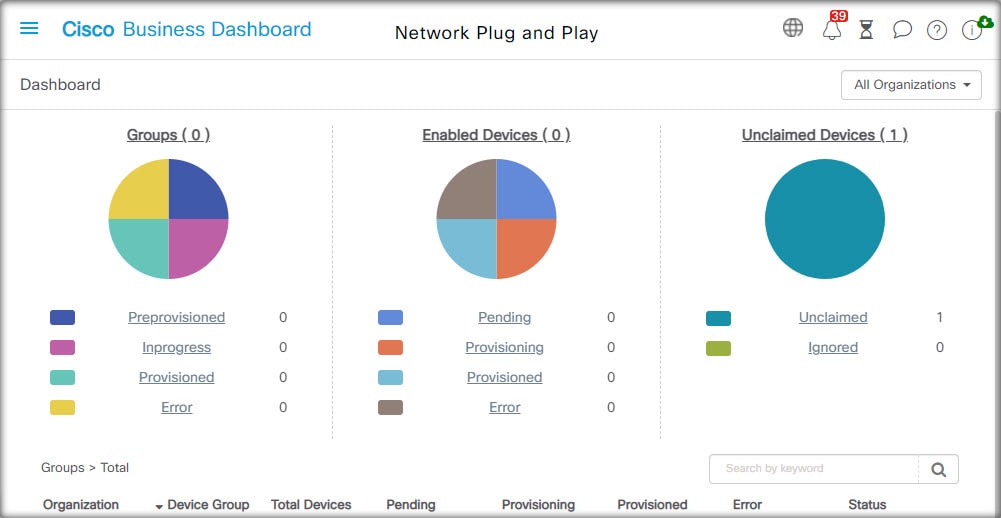
The Network Plug and Play Dashboard provides an overview of the devices currently being provisioned using Network Plug and Play.
Three charts are displayed showing the device status broken down by:
Each chart shows the number of devices or groups in each of the states listed. You can click on the state heading on any
of the charts to see a detailed list of devices or groups that fall into that category. The following table provides a breakdown
of the different statuses:
Table 1. Network Plug and Play Dashboard – Status Definitions
|
Status
|
Description
|
|
Groups
|
|
Pre-provisioned
|
Device groups with PnP-enabled devices in the Pending state only.
|
|
In Progress
|
Device groups with some PnP-enabled devices in the Pending state and some in the Provisioning or Provisioned state.
|
|
Provisioned
|
Device groups where all PnP-enabled devices are in the Provisioned state.
|
|
Error
|
Device groups with one or more PnP-enabled devices in the Error state.
|
|
Enabled Devices
|
|
Pending
|
Devices in the inventory that have been enabled for PnP, but have not yet contacted the PnP server.
|
|
Provisioning
|
Devices that have contacted the PnP server and begun provisioning but have not completed the provisioning process.
|
|
Provisioned
|
Devices that have been successfully provisioned using PnP.
|
|
Error
|
Devices where the PnP provisioning process has failed.
|
|
Unclaimed Devices
|
|
Unclaimed
|
Devices that have contacted the PnP server but are not defined in the inventory.
|
|
Ignored
|
Unclaimed devices that have been explicitly ignored by the user.
|
You can restrict the data displayed to a specific organization using the organization drop-down at the top right of the page.
When viewing device groups, type all or part of a group name in the search box to limit the groups displayed in the table.
Or you can enter a device name, product ID or serial number in the search box when viewing provisioning rules to display the
current status of an individual device.

Note
|
The chart for unclaimed devices is only displayed to Administrators who are viewing data for All Organizations.
|
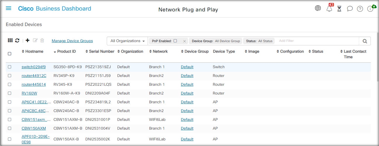
Managing Enabled Devices
Enabled Devices are devices in the inventory that have been configured for provisioning with an image or configuration file,
or were previously discovered by Cisco Business Dashboard and have attempted to connect using the Network Plug and Play protocol. An Enabled Device that has been configured with an
image or configuration file will have that image and/or configuration applied to the device at the next opportunity. If the
device is connected to and managed by the Dashboard, the changes will be applied immediately. Otherwise, the changes will
be applied the next time the device is connected - either via a probe or direct management, or when it checks in using the
Network Plug and Play protocol. An Enabled Device may also be set to apply changes during the next change window, in which
case the changes will be delayed until the next change window after the device checks in.
To create a new Enabled Device, follow the steps below.
-
Navigate to Network Plug and Play >Enabled Devices.
-
Click the ✚(plus) icon to add a new enabled device to the inventory.
Note
|
You may also click the upload icon to add devices in bulk using a csv file. Template csv files may be downloaded from the
Network Plug and Play > Configurations page by opening the configuration template to be used for the devices and selecting Download CSV Template from the Actions dropdown.
|
-
Fill out the Add New Device form with the requested parameters, including identifying details for the device, the organization, network and device group
it should belong to, then click Next.
-
Optionally, select a firmware image to be applied to the device. If you choose Default for the image, the device will use the image that is designated as the default for the product ID at the time the device
connects to the server.
Note
|
You may use the checkbox on this page to delay the provisioning of the new device until the next change window. However, this
is rarely appropriate when creating a new device, as a new device is not usually an active part of the network until after
provisioning is complete.
|
-
Optionally, select a configuration to be applied to the device, along with the version of the configuration if there is more
than one version. If the configuration is a template containing placeholders, a form will be displayed prompting for the values
that should be used for this device. Complete these fields as necessary. If the template makes use of parameters defined by
the system, click on the checkbox to display the values that will be used.
-
Click Next to proceed to the Summary screen. Review the data entered to ensure it is correct. You can also review the final device configuration in the preview
window at the bottom. When you are satisfied, click Finish.
To edit an existing device, follow the steps below.
-
Navigate to Network Plug and Play>Enabled Devices.
-
Check the checkbox for the device to be modified and click Edit. Alternatively, you can click the name of the device.
-
Click Next to display the Provision Device screen. Change the image and/or configuration file if required and make any changes to the parameter values associated with
the configuration. Optionally, check the checkbox to ensure that changes will be applied during the change window.
-
Click Next to proceed to the Summary screen. Review the data entered to ensure it is correct. You can also review the final device configuration in the preview
window at the bottom. When you are satisfied, click Finish.
Note
|
If the image or configuration file settings are changed for a device that has already been provisioned, that device's state
will reset to pending, and the device will be re-provisioned.
|
To remove an Enabled Device, follow the steps below.
-
Navigate to Network Plug and Play >Enabled Devices.
-
Check one or more checkboxes for the devices to be removed and click the delete icon.
Note
|
If an Enabled Device is deleted when that device is otherwise known to the Dashboard and the device is online, only the image
and configuration files settings for that device will be removed. The device will remain in the inventory similar to any other
managed device. If a device subsequently connects to the Dashboard using PnP, a new entry will be added to the Enabled Devices
table.
|
Unclaimed Devices
Note
|
The Unclaimed Devices page is only available to Administrators.
|
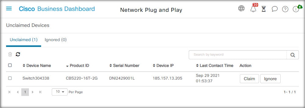
An unclaimed device is one that has connected to the service, but there is no device record in the inventory that matches
the device. To see a list of unclaimed devices, and to claim an unclaimed device so it can be managed using Network Plug and
Play, follow the steps below.
-
Navigate to Network Plug and Play >Unclaimed Devices and select the Unclaimed tab.
-
Click the claim button for the device to be managed.
-
Fill out the Unclaimed Device form with the requested parameters, including the organization, network and device group it
should belong to, then click Next.
-
Optionally, select a firmware image to be applied to the device. If you choose Default for the image, the device will use the image that is designated as the default for the product ID at the time the device
connects to the server.
-
Alternatively, select a configuration to be applied to the device, along with the version of the configuration if there is
more than one version. If the configuration is a template containing placeholders, a form will be displayed prompting for
the values that should be used for this device. Complete these fields as necessary.
If the template makes use of parameters defined by the system, you can check the checkbox to display the values that will
be used.
-
Click Next to proceed to the Summary screen. Review the data entered to ensure it is correct. You can also review the final device configuration in the preview
window at the bottom. When you are satisfied, click Finish.
To remove a device from the Unclaimed list without provisioning it, follow the steps below.
-
Navigate to Network Plug and Play>Unclaimed Devices and select the Unclaimed tab.
-
Click Ignore for the device you wish to remove from the list.
The devices will be moved to the Ignored list and no further action will be taken. To reclaim an ignored device, follow the steps below.
-
Navigate to Network Plug and Play>Unclaimed Devices and select the Ignored tab.
-
Click the Unignore button for the device to be reclaimed.
The devices will be moved to the Unclaimed list, and you can claim the devices as described above.
Auto Claiming Devices
Note
|
The Auto Claim page is only available to Administrators.
|
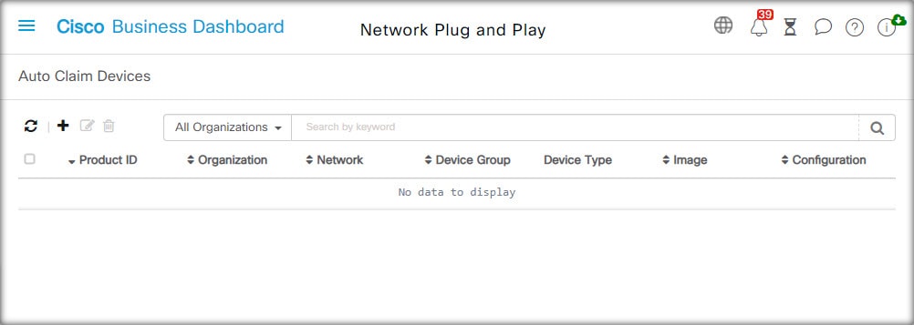
Unclaimed devices can be automatically claimed and provisioned by the server by creating an Auto Claim rule for that product
ID. To create an Auto Claim rule, follow the steps below.
-
Navigate to Network Plug and Play>Auto Claim Devices.
-
Click the ✚(plus) icon to create a new Auto Claim rule.
-
Fill out the Auto Claim Device form with the requested parameters, including the Product ID (PID) to be matched, and the organization,
network, and device group the newly claimed device should belong to, then click Next.
-
Optionally, select a firmware image to be applied to the device. If you choose Default for the image, the device will use the image that is designated as the default for the product ID at the time the device
connects to the server.
-
Alternatively, select a configuration to be applied to the device, along with the version of the configuration if there is
more than one version. If the configuration is a template containing placeholders, a form will be displayed prompting for
the values that should be used for this device. Complete these fields as necessary.
If the template makes use of parameters defined by the system, you can check the checkbox to display the values that will
be used.
-
Click Next to proceed to the Summary screen. Review the data entered to ensure it is correct. You can also review the final device configuration in the preview
window at the bottom. When you are satisfied, click Finish.
New devices that are not present in the inventory will be compared against the list of Auto Claim rules. If there is a match,
a new device record will be created in the inventory with the image and configuration file defined by the Auto Claim rule. The device will then be provisioned accordingly. If the device does not match an Auto Claim rule, it will be added to the Unclaimed list and no further action will be taken.
Device Firmware Images
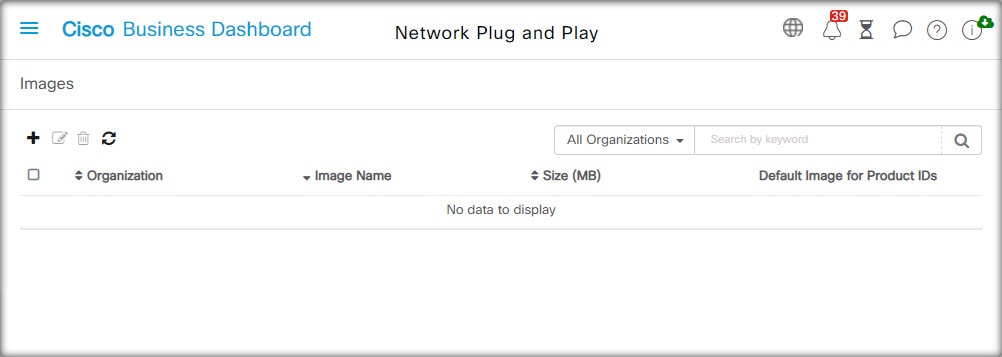
The Images page allows you to upload firmware images that can then be deployed to the devices.
Firmware images can be designated as the default image for different platforms, allowing you to update the firmware across
an entire family of devices very easily. Firmware images are specific to an organization and can only be used for provisioning
devices associated with the same organization.
To upload a firmware image, follow the steps below.
-
Navigate to .
-
Click the ✚(plus) icon.
-
Select the organization for the image from the dropdown.
-
Drag a firmware image from your PC and drop it on the target area of the Upload File window. Alternatively, click the target area and select a firmware image to upload.
-
Click Upload.
You can change the filename or designate an image as the default image for one or more device types. To modify the filename
or designate an image as a default image, follow the steps below.
-
Navigate to Network Plug and Play >Images.
-
Select the radio button for the image in the Images table and click edit.
-
If desired, modify the filename of the image using the textbox provided.
-
Optionally enter a comma-separated list of product IDs into the Default Image for Product IDs field. Product IDs can contain the wildcard characters ‘?’, representing a single character, and ‘*’, representing a string
of characters.
-
Click Save.
To remove an image, follow the steps below.
-
Navigate to Network Plug and Play >Images.
-
Select the radio button for the image to be deleted and click delete.
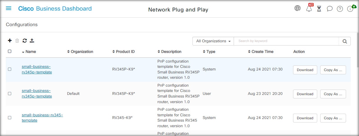
Device Configuration Files
The Configurations page allows you to upload or create configuration files that can then be deployed to the devices. Configuration
files are specific to an organization and can only be used for provisioning devices associated with the same organization.
Configuration files can be simple text files, or can contain placeholders and associated metadata to allow the same configuration
file to be used with multiple devices, while still allowing for unique parameters to be set on a device by device basis. For
example, a single configuration template could be applied to multiple devices, but allow the hostname to be specified individually
for each device.
Several configuration templates are included with the Dashboard application as system templates and are available to all organizations.
These templates allow commonly changed settings to be modified, and can be used as is, or copied and used as a basis for new
templates. For more information on the syntax of the configuration templates, See Appendix A: Managing Configuration Templates.
To create a new configuration manually, follow the steps below.
-
Navigate to Network Plug and Play>Configurations.
-
Click the ✚(plus) icon.
-
The template editor opens with a blank area for the configuration on the left, and a form on the right for managing the metadata
associated with the template.
Enter a name for the configuration in the field at the top left. Select an organization and enter a comma-separated list of
product IDs that support this configuration in the fields on the right. Optionally, enter a description. Product IDs can contain
the wildcard characters ‘?’, representing a single character, and ‘*’, representing a string of characters.
-
Create the configuration by typing or pasting text into the text area on the left. If necessary, make the appropriate changes
to the metadata using the controls on the right.
You can use the Preview button to see how the configuration template will appear when it is assigned to a device.
-
When you are satisfied with the configuration, click Save.
To upload a configuration file, follow the steps below.
-
Navigate to Network Plug and Play >Configurations.
-
Click the Upload icon.
-
Select the organization for the configuration from the dropdown. Specify a name for the configuration and optionally add a
description.
-
Drag a configuration file from your PC and drop it on the target area of the Upload File window. Alternatively, click the target area and select a configuration file to upload.
-
Click Upload.
You can click on the filename of the uploaded configuration file to view the contents in the template editor, if you wish.
To remove a configuration, follow the steps below.
-
Navigate to Network Plug and Play >Configurations.
-
Check one or more checkboxes for the configurations to be removed and click the delete icon.
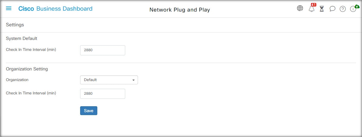
Managing Settings
The Network Plug and Play Settings page allows you to control the operation of the Network Plug and Play Protocol.
The Check In Time Interval controls how frequently a device will connect to the Network Plug and Play service after initial provisioning. To modify
this parameter, follow the steps below.
-
Navigate to Network Plug and Play>Settings.
-
Enter the desired interval between connections in the field provided. The time is in minutes, and the default is 2880 minutes,
or two days.
-
Click Save.
The Check In Time Interval is set for the system as a whole, but can be overridden at the organization level. If no interval is set for the organization,
then the system value is used.
Configuring the Certificate
The certificate automatically generated by Cisco Business Dashboard during first startup is a self-signed certificate. In most cases, this will not be sufficient for the certificate to be accepted
by the Network Plug and Play client, and it will be necessary to generate a new certificate. When generating a new self-signed
certificate or certificate signing request (CSR), the Dashboard will include the contents of the Common Name field in the Subject Alternative Name field in addition to any values specified in the Subject Alternative Name field on the GUI.
For more information on configuring the Dashboard’s certificate, see Managing Certificates.
 Feedback