Feature Summary and Revision History
Feature Description
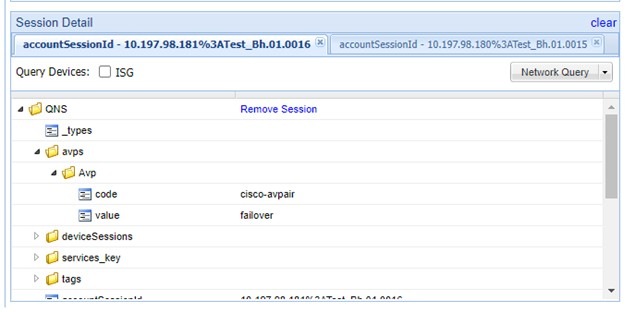
Remote Authentication Dial-In User Service (RADIUS) attributes are used to define specific authentication, authorization, and accounting (AAA) elements in a user profile, which are stored on the RADIUS program.
Enable the RADIUS endpoint to dynamically create pods on a designated node or host. This feature is necessary to ensure nodes meet specific security and regulatory parameters are geographically closer to the datacenter. Node affinity determines the node where cnAAA creates the RADIUS endpoint pods, based on affinity towards a node or group of nodes. Node affinity is a set of rules that defines custom labels on nodes and specifies label selectors within the pods. Based on these rules, the scheduler determines the pod's placement location.
 Note |
If you do not specify a node, then the Kubernetes scheduler determines the node where the RADIUS endpoint creates a pod. |
cnAAA supports both IPv4 and IPv6 connectivity on its external interfaces/endpoints (inbound and outbound).
Overview
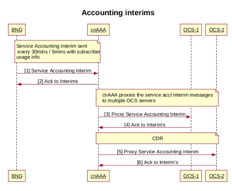
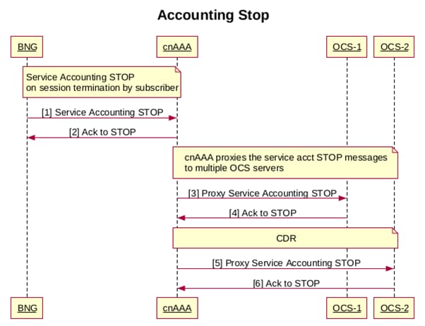
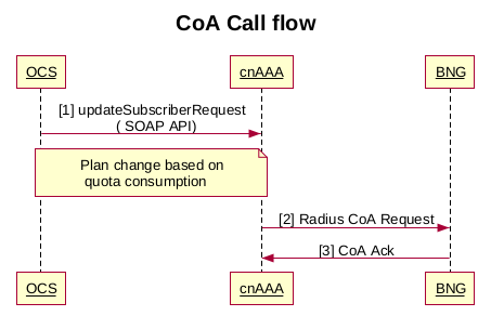
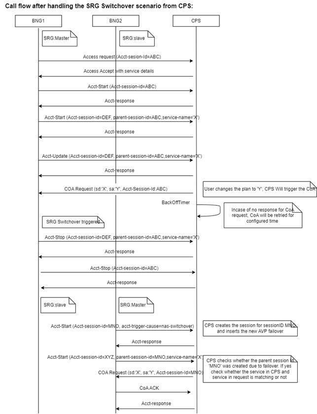
The CPC supports RADIUS for managing Authentication, Authorization, and Accounting (AAA) for users connecting to a network service. It ensures secure network access and precise session tracking for accurate billing and resource management. The feature also supports interim updates and Change of Authorization (CoA) requests, allowing real-time adjustments to user services. The Broadband Network Gateway (BNG) acts as the RADIUS client, sending requests to CPC based on user information.
The following are the core functionalities of the CPC in handling RADIUS requests:
-
Access-Request
-
Accounting-Request
Configure the node for the RADIUS Endpoint Pod
This section describes how to specify the node or host where the RADIUS endpoint must spawn the pod.
Note |
Configuration changes to the RADIUS endpoint cause the endpoint to restart automatically. Cisco recommends making such changes only within the maintenance window. |
Mandatory RADIUS configuration
To configure the RADIUS server with essential parameters for optimal network performance and security, use the following configuration:
radius bind-ip <bind IP address>
radius replicas 2
radius settings request-timeout-ms 5000
radius settings max-tries 1
radius async-threading-configuration default-processing-threads 100
radius async-threading-configuration default-action-priority 5
radius async-threading-configuration default-action-threads 100
radius async-threading-configuration default-action-queue-size 400000
radius async-threading-configuration default-action-drop-oldest-when-full true
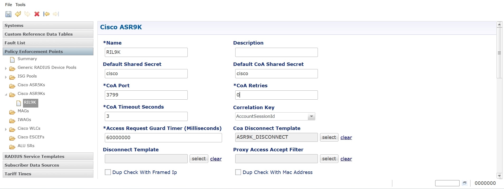
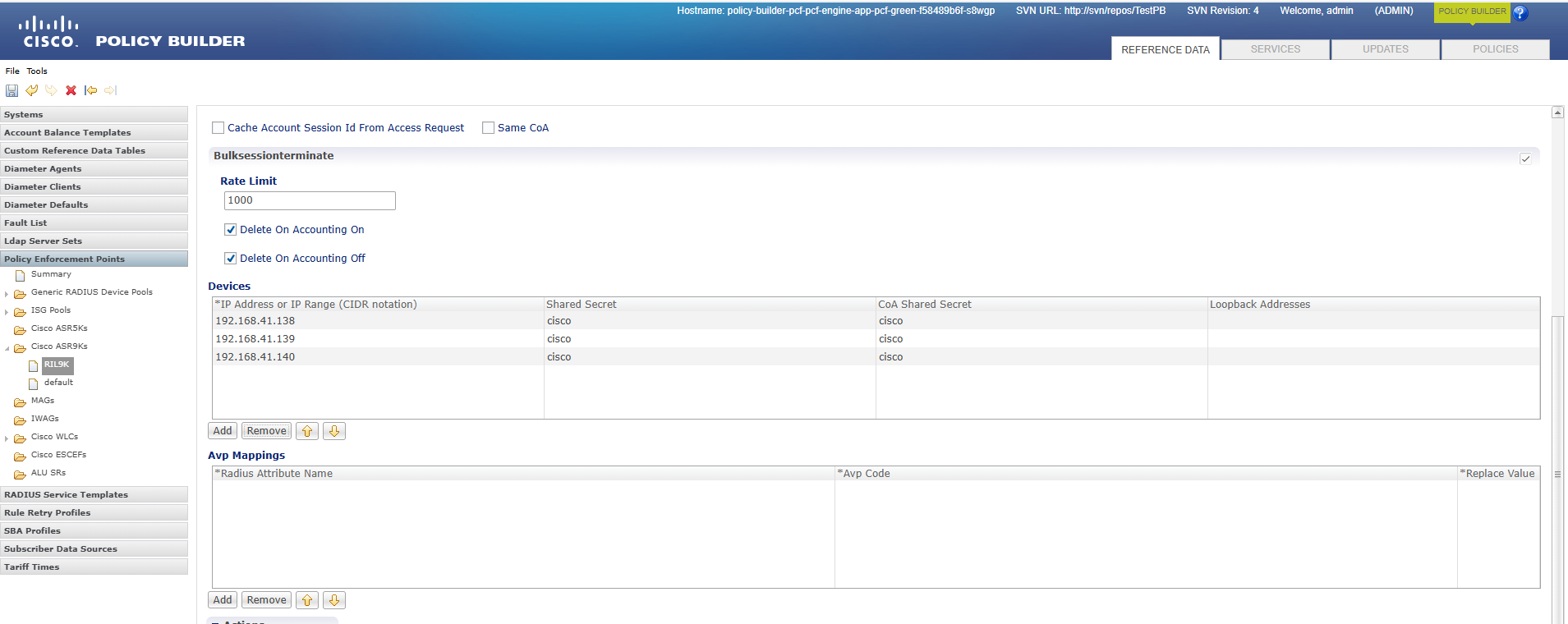
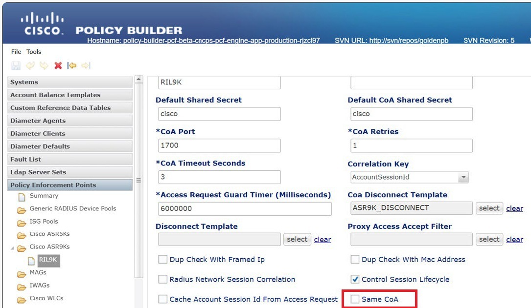
radius device-group ASR9K
default-shared-secret <secret value>
default-coa-shared-secret <secret value>
coa-port 3799
coa-timeout-seconds 3
device <BNG Device Name>
ip <BNG IP Address>
shared-secret <secret value>
coa-shared-secret <secret value>
loopback-addresses [ <loopback addresses> ]
exit
radius server-group <Server Group Name>
servers <server name>
primary <primary OCS IP Address>
secondary <secondary OCS IP Address>
nas-ip <nas p address>
accounting-port 1803
authorization-port 1802
auth-protocol PAP
radius-password <radius password>
shared-secret <secret value>
timeout-seconds 3
test-message false
test-userid test
test-password test123
thread-pool-size 330
max-proxy-queue-size 50000
server-type online (or) offline
retries 0
exit
radius properties grpc.executors
value 5
exit
radius properties grpc.timeoutMs.processing
value 5000
exit
radius properties io.netty.eventLoopThreads
value 16
exit
radius properties parallelChannelCount
value 5
exit
radius properties prometheusPort
value 9099
exit
radius properties radiusCorePoolSize
value 20
exit
radius properties radiusMaxQueue
value 4000
exit
radius properties traps.tps
value 4000
exit
radius properties udpMaxQueue
value 4000
exit
radius properties udpPoolSize
value 20
exit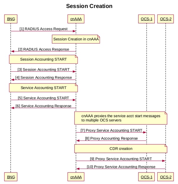


 Feedback