Inventory

Inventory

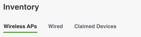
The inventory tab displays MAC addresses organized under the columns:

  • Wireless Access Points

  • Wired switches

  • Claimed devices

Figure 1. Inventory tab

The Inventory tab lists every access point (AP) and switch, regardless of location. Once you map a controller to a location, the APs in that location appear under that location in the manage page. The mapping can be performed using Prime, DNAC, or Catalyst Center. After you map the APs to a floor and assign a switch to a location, they appear in the manage page under their locations.

When you add a controller and switch to a connector, and if previous IoT streams were performed on that controller or switch, the system sends the TDL subscription and retrieves data from TDL through Cisco Spaces. The inventory process has not changed. The available actions in the inventory tab are select, delete, and export.

If there are stale APs or switches, you can delete them from the inventory tab. No other actions can be performed on this tab.
Configure wireless APs

Use this task to customize and manage the configuration of your wireless APs, such as enabling BLE modes, monitoring installed applications, viewing request history, exporting AP information, or deleting APs.

Follow these steps to configure and manage wireless APs:

Before you begin

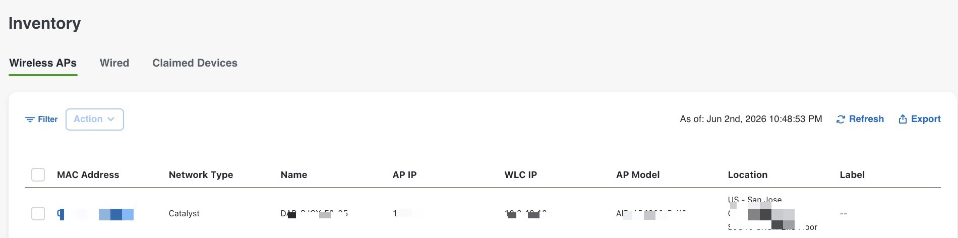
The Wireless APs tab consists of these columns: MAC Address, Network Type, Name, AP ID, WLC ID, AP Model, Location and Label.
Figure 2. Wireless APs tab

Procedure


Step 1

Select the MAC address of the AP you want to configure under the Wireless APs tab.

Step 2

The AP Configuration panel appears on the right navigation.

Step 3

In the AP Information panel, review these: MAC Address, Network Type, Name, AP IP, WLC IP, AP Model, Location and Label.

Step 4

In the Settings panel, enable BLE by toggling the BLE switch. To enable additional BLE modes, select any of these options after enabling BLE: Scan, Transmit and Dual.

Step 5

In the Request History panel, check these columns: Operation, Status, Initiated At, Last Updated At, Status Message, Config Source and Destination AP.

Note


Click the Refresh button to update all these AP configuration details.

Step 6

To refresh the list of wireless AP MAC addresses, click the Refresh button under the Wireless APs tab.

Step 7

To export a specific MAC address, select the desired AP under the Wireless APs tab and click the Export button. The details are downloaded as a .csv file to your local system.

Step 8

To delete the Wireless AP, check the checkbox for the desired MAC address and click on the Action drop down button. Click Delete to confirm.


Configure wired switches

Use this task to access, configure, and maintain wired switches in your environment. This process covers viewing switch information, managing installed apps, exporting switch data, and deleting wired switches.

Follow these steps to configure and manage wired switches:

Before you begin

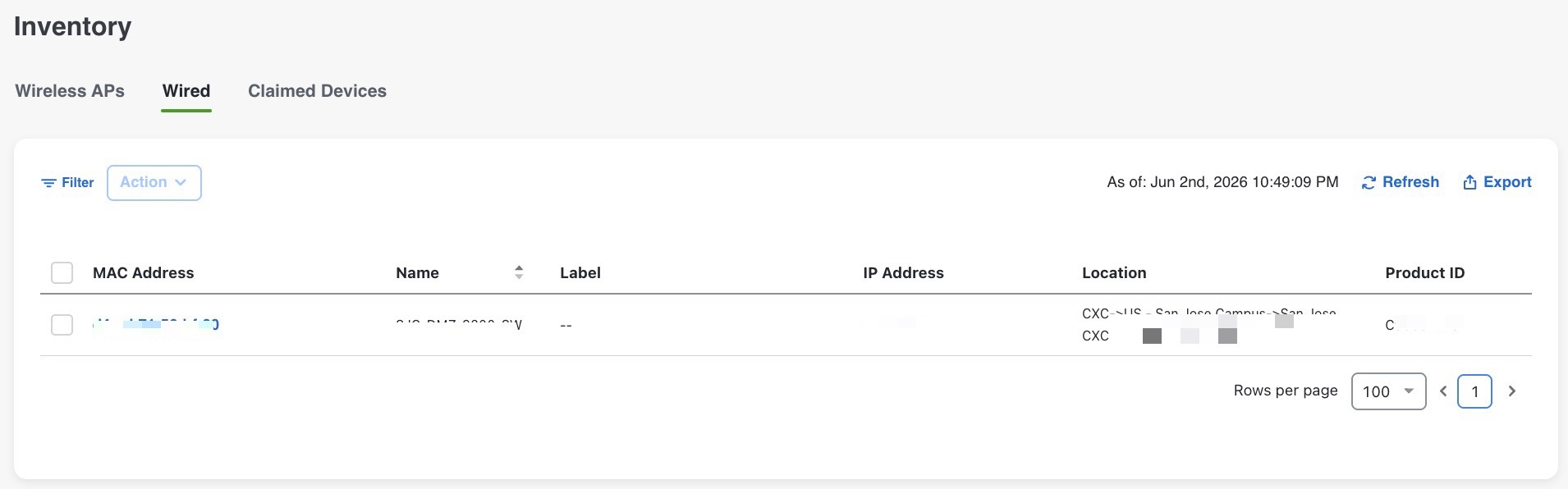
The Wired tab consists of these columns: MAC Address, Name, Label, IP Address, Location and Product ID.
Figure 3. Wired switches tab

Procedure


Step 1

Select the MAC address of the AP you want to configure under the Wired switches tab.

Step 2

The Wired Gateway panel appears on the right navigation.

Step 3

In the Wired Information panel, review these: MAC Address, Name, Label, IP Address, Location and Product ID.

Step 4

In the Energy Information panel, review these: Device, Event, Address, Module, Module Energy, Module Energy Reset Time, Module Number, Module Power Budget, Module Power Instant, Module Power Peak and Module Type.

  1. In the Module Details part, review these columns: Module Number, Host ID, Available Power, Chassis Number, Free Port, Max Power, IP Address, Number of Ports, Power Pool Index, Remaining Power, Total Consumed Power, Used Ports and Used Power.

  2. In the Port Details part, review these: Interface Name, Device Name, IP Address, Event Time, Admin State, Max. Power Drawn, Operating Power, Operating State, PD Class, Max. Admin Power, Power Consumption, Power from PSE, Power to PD and Power Used.

Step 5

In the Request History part, review these: Operation, Status, Initiated At, Last Updated At, Status Message, Config Source and Destination AP.

Step 6

To refresh the list of wired switch MAC addresses, click the Refresh button under the Wired tab.

Step 7

To export a specific MAC address, select the desired AP under the Wired tab and click the Export button. The details are downloaded as a .csv file to your local system.

Step 8

To delete the Wired switches, check the checkbox for the desired MAC address and click on the Action drop down button. Click Delete to confirm.


Configure claimed devices

Use this task when you need adjust device-specific parameters such as beacon configuration or telemetry, or onboard additional devices (Cisco, Meraki, or third-party) into your asset inventory.

Follow these steps to configure claimed devices:

Before you begin

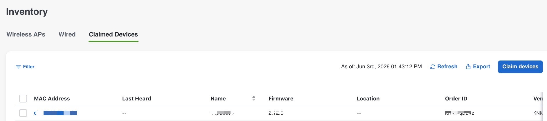
The Claimed Devices tab consists of these columns: MAC Address, Last Heard, Name, Firmware, Location, Order ID, Vendor ID and Model.
Figure 4. Claimed devices tab

Procedure


Step 1

The Base MAC Address panel appears on the right navigation.

Step 2

In the Device Information panel, review these: MAC Address, Last Heard, Name, Firmware, Location, Order ID, Vendor ID, Model and Label.

Step 3

In the Sensor Information panel, check if the sensor data is available for that device.

Step 4

In the Beacon Information panel, check if the beacon data is available for that device.

Step 5

In the Request History panel, review these: Operation, Status, Initiated At, Last Updated At, Status Message, Config Source and Destination AP.

Step 6

To refresh the list of claimed devices MAC addresses, click the Refresh button under the Claimed Devices tab.

Step 7

To export a specific MAC address, select the desired AP under the Claimed Devices tab and click the Export button. The details are downloaded as a .csv file to your local system.

Step 8

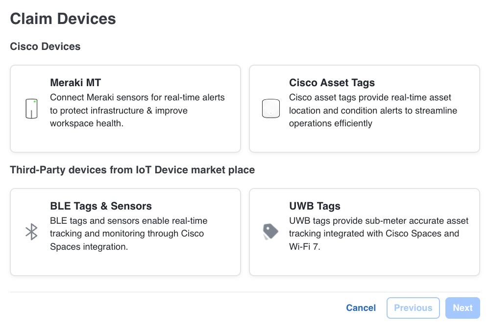
To add new claimed devices, click on the Claim devices button. The Claim Devices window appears.

Figure 5. Claim devices tab
  1. Cisco Devices: allow Meraki MT and Cisco Asset Tags.

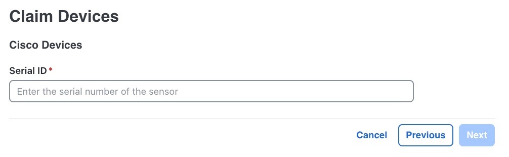
    1. Meraki MT: Select Meraki MT and click Next. Enter the Serial ID and click Next.

      Figure 6. Serial ID tab
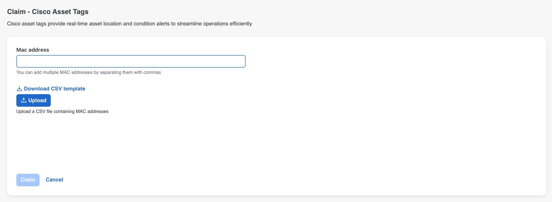
    2. Cisco Asset Tags: Select Cisco Asset Tags and click Next. The Claim - Cisco Asset Tags page appears. You can add one or more MAC addresses in the Mac address. Download the CSV template by clicking on the Download CSV template button and re-upload a CSV file containing MAC addresses using the Upload button. Click Claim to confirm. The number of tags claimed or failed is displayed.

      Figure 7. Claim-Cisco asset tags tab
  2. Third-Party devices from IoT Device market place: allows third-party BLE Tags and Sensors and UWB Tags.

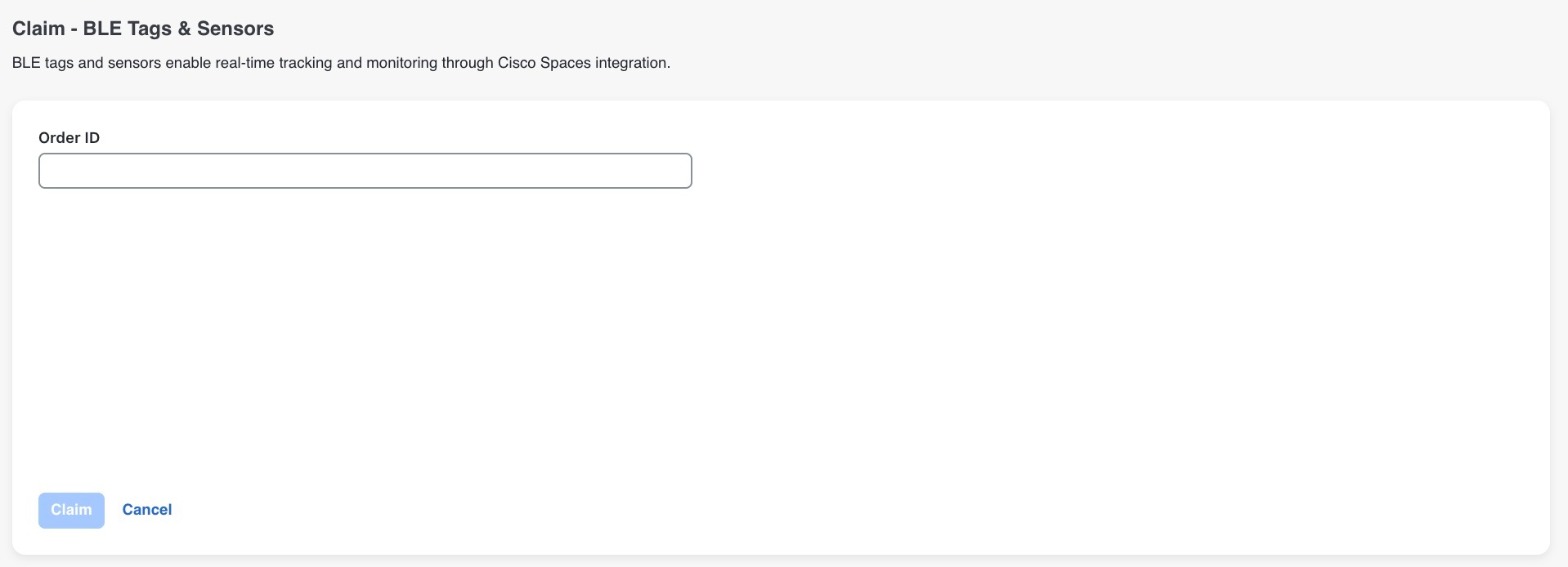
    1. BLE Tags and Sensors: Select BLE Tags and Sensors and click Next. The Claim - BLE Tags & Sensors window appears. Enter the Order ID and click Claim.

      Figure 8. BLE tags & sensors tab
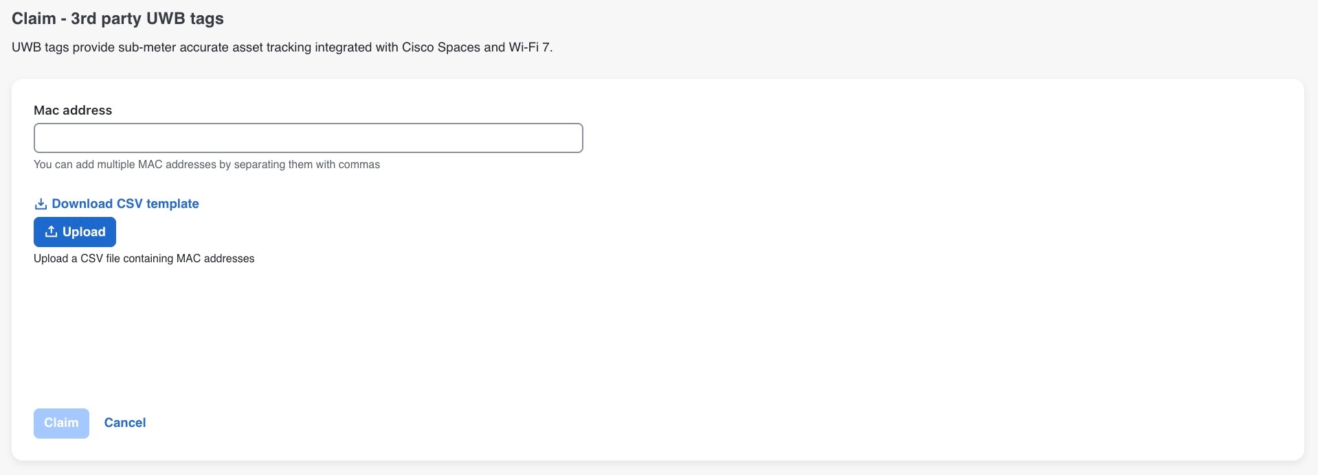
    2. UWB Tags: Select UWB Tags and click Next. The Claim - 3rd party UWB tags window appears. You can add one or more MAC addresses in the Mac address. Download the CSV template by clicking on the Download CSV template button and re-upload a CSV file containing MAC addresses using the Upload button. Click Claim to confirm. The number of tags claimed or failed is displayed.

      Figure 9. 3rd party UWB tags tab