Connecting a Cisco Reader Module
Available Languages
Table Of Contents
Connecting a Cisco Reader Module
Physical Overview and Port Description
Installing the Cisco Reader Module
Connecting a Cisco Reader Module
Overview
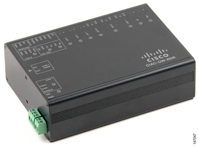
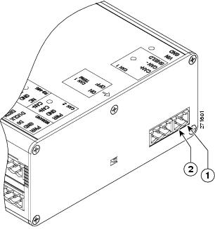
The optional Cisco Reader Module (Figure 3-1) is similar to the Cisco Physical Access Gateway, providing the same ports for Weigand readers and other input and output devices. The Cisco Reader Module is attached to a Cisco Physical Access Gateway to provide additional connections for one or two doors, but does not include Ethernet connections for the IP network. Power is supplied using the 2-pin connector for 12 to 24 VDC external power.
Figure 3-1 Cisco Reader Module
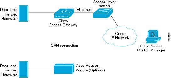
The Cisco Reader Module is connected to a required Cisco Physical Access Gateway using a CAN connection, as shown in Figure 3-2.
Figure 3-2 Cisco Reader Module connected to the Cisco Physical Access Gateway
Package Contents
Each Cisco Reader Module includes the following:
•
Six resistors (1K) for input supervision
•
•
•
•
Physical Overview and Port Description
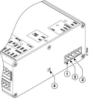
Each Cisco Reader Module includes ports for connecting up to two doors and associated input and output devices, as shown in Figure 3-3 and Figure 3-4.
Figure 3-3 Cisco Reader Module Ports and Connectors
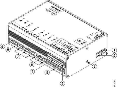
Figure 3-4 Cisco Reader Module Ports and Connectors: Top View
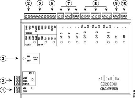
The following items are shown in Figure 3-3 and Figure 3-4:
Power
Two-pin connector for Voltage In (VIN) and Ground (GND) to connect a 12 to 24 VDC external power source.
CAN interfaces
A 3-wire CAN bus is used to connect additional modules.
Note
CAN terminator
The CAN terminator switch is set to ON for the last device in a CAN wiring bus. This switch is set to set to OFF for all other devices in the CAN bus.
Serial Interface
The RS-485 interface is not supported in this release.
Weigand Interface
One 10-pin Weigand/clock and data reader interface. This interface can be configured as two 5-pin Weigand/clock and data interfaces for installations where a 5-pin interface is sufficient.
Note
Input interfaces
Three input interfaces used to sense the contact closure. Each input can be configured as supervised or unsupervised and can be configured to sense a Normally Open (NO) or Normally Closed (NC) contact.
•
•
Output interfaces
Three Form C (5A @ 30V) relay output interfaces. Each output can be configured as either Normally Closed (NC) or Normally Open (NO).
•
•
Notes:
•
•
•
–
–
PF
Power fail input: an unsupervised input that raises a "power fail" alarm when the circuit is open. Can be configured as an additional unsupervised port. An unsupervised input indicates only normal or alarm. The corresponding LED is red when circuit is open (when no input is connected).
TM
Tamper input: an unsupervised input that raises a "tamper" alarm when the circuit is open. Can be configured as an additional unsupervised port. An unsupervised input indicates only normal or alarm. The corresponding LED is red when circuit is open (when no input is connected).
Status LEDs
Table 3-1 describes the Gateway module status LEDs:
Installing the Cisco Reader Module
Installing the Cisco Reader Module is similar to installing the Gateway, except for the following:
•
•
•
Before You Begin
Before you install a Cisco Reader Module, verify the following:
•
•
Installation Procedure
To install the Cisco Reader Module, perform the following procedure:
Step 1
Step 2
a.
b.
See Power Options and Requirements, page 1-10 for more information.
Figure 3-5 Power Connection: for the Cisco Reader Module
The following items are shown in Figure 3-5:
DC power
GND (ground)Connects the DC ground wire to the module.
DC power
Voltage In (VIN)Connects the DC Voltage In (VIN) wire to the module.
Step 3
a.
b.
c.

Note
Note
See Optional Expansion Modules, page 1-6 for more information:
Figure 3-6 CAN1 Connections: Cisco Physical Access Gateway and Reader Module
The following items are shown in Figure 3-6:
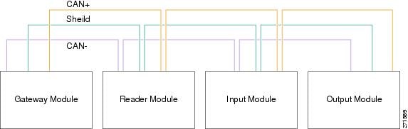
Figure 3-7 CAN Bus Wiring
Step 4
•
•
Figure 3-8 shows the location of the Weigand interface connections.
Table 3-2 describes the connections for 10-pin and 5-pin reader interface connections. The wire connectors from the reader device are shown in parentheses. If attaching a second reader, use the alternative connections shown in the column on the far right.
Figure 3-8 Weigand Interface on the Gateway and Reader Modules
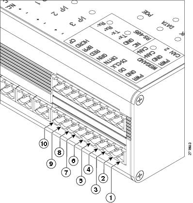
Table 3-2 Weigand Reader Wiring for 10 or 5 Pin Connections
PWR
+12v
PWR (red) 1
PWR (red)
PWR (red)
GND
Ground
GND (black)
GND (black)
GND (black)
D0
Data 0
D0 (green)
D0 (green)
----------
D1/CLCK
Data 1
D1/CLCK (white)
D1/CLCK (white)
----------
DRTN
Shield
DRTN (shield)
DRTN (shield)
DRTN (shield)
GRN
Output 2
GRN (orange)
GRN (orange)
----------
RED
Output
RED (brown)
---------- 3
GRN (orange)
BPR
Output (Beeper)
BPR (yellow)
----------
----------
HCRD
Hold Control
HCRD (blue)
----------
D1/CLCK (white)
CP
Card Present
CP (purple)
----------
D0 (green)
1 Wire colors are shown in parentheses.
2 Outputs show the LED color and reader wire color (in parentheses). For example, "GRN (orange)" supports a green LED. Attach the orange wire from the reader device.
3 ---------- means the wire slot is not used.
Step 5
a.
b.
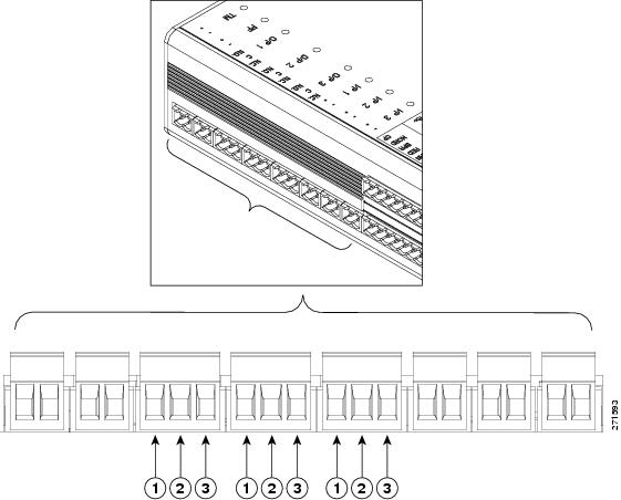
Figure 3-9 Input Connections: Cisco Physical Access Gateway and Reader Module
c.
Note
Figure 3-10 Input Connections: Cisco Physical Access Gateway and Reader Module
The following items are shown in Figure 3-10:
Step 6
a.
b.
–
–
–
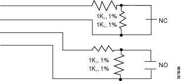
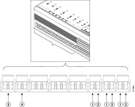
Figure 3-11 Output Connections: Cisco Physical Access Gateway and Reader Module
The following items are shown in Figure 3-11:
Step 7
 Feedback
Contact Cisco
- Open a Support Case

- (Requires a Cisco Service Contract)
This Document Applies to These Products
- Collaboration Endpoints - Retired Products
- Conferencing - Retired Products
- Contact Center - Retired Products
- Optical Networking - Retired Products
- Routers - Retired Products
- Security - Retired Products
- Servers - Unified Computing (UCS) Retired Products
- Storage Networking Retired Products
- Switches - Retired Products
- Video - Retired Products
- Wireless - Retired Products