Overview
Available Languages
Table Of Contents
The Cisco Physical Access Gateway
Support for Multiple Cisco Physical Access Gateways
CAN Bus Connections for Optional Modules
Installation and Configuration Summary
Power Options and Requirements
Installing Surge Suppressors on Output Device Connections
Connect Reader Devices with Module Power Off
Mounting a Gateway or Optional Module
Wall Mounting a Gateway or Optional Module
Overview
This document provides information to install and configure the components located near each door of a Cisco Physical Access Control system.
This document includes the following information:
–
The Cisco Physical Access Gateway
–
–
–
•
•
–
–
•
System Overview
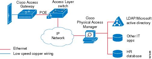
Cisco Physical Access Control is a comprehensive solution of hardware and software components, connected through an IP network as shown in Figure 1-1.
Figure 1-1 Cisco Physical Access Control: System Overview
The Cisco Physical Access Gateway
A Cisco Physical Access Gateway is installed near each door to provide processing and control for the connected door hardware, such as card readers, locks, and other input and output devices. This architecture allows access control to be deployed incrementally, door by door, eliminating the central panel and simplifying system design, wiring, and planning.
The Gateway is required, and can control up to two doors. Each Gateway supports the following:
If additional connections are required, you can connect up to 15 optional modules using a three-wire Controller Area Network (CAN) bus. These modules can be added or removed without affecting the operation of the system or other modules. See Optional Expansion Modules for more descriptions of the available modules.

Note
Related Documentation
For installation and configuration instructions, see Chapter 2, "Installing and Configuring the Cisco Physical Access Gateway". See the Cisco Physical Access Manager User Guide for advanced configuration and management of the access control components.
Support for Multiple Cisco Physical Access Gateways
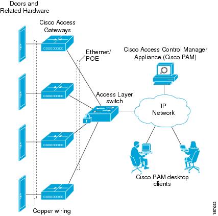
A Cisco Physical Access Gateway is installed for each door, and connected to the IP network using an Ethernet connection, as shown in Figure 1-2. This network connection provides communication with the Cisco Physical Access Manager for advanced configuration, and management with the other Gateways in the system. If the network connection is lost, the Gateway continues to provide access control functionality for the connected door devices.
Figure 1-2 Multiple Cisco Physical Access Gateways
Note
Cisco Physical Access Manager
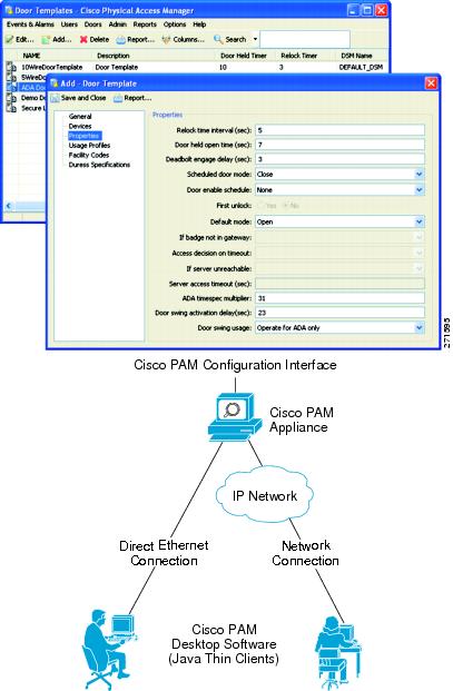
The Cisco Physical Access Manager appliance (Cisco PAM) is a hardware and software solution that provides advanced configuration, monitoring, and report generation for the entire system. Each Cisco Physical Access Gateway is connected to the Cisco PAM appliance over an Ethernet-based IP network, as shown in Figure 1-2. A Java-based desktop application is installed on a PC connected to the network, and used to configure and monitor the system, as shown in Figure 1-3.
Figure 1-3 Configuring and Monitoring Using the Cisco Physical Access Manager
The Cisco PAM appliance includes the following main features:
•
•
•
•
•
•
•
•
•
•
•
•
•
Related Documentation
For more information on the Cisco PAM appliance, including installation and configuration instructions, see the Cisco Physical Access Manager User Guide.
Optional Expansion Modules
Each Cisco Physical Access Control system includes at least one Cisco Physical Access Gateway to provide processing and connections for input and output devices such as card readers and locks. If additional connections are required, you can add optional modules to extend the functionality of the Gateway.
Module Features
Figure 1-4 shows the modules for a Cisco Physical Access Control system. Table 1-1 summarizes the features for each module.
Figure 1-4 Cisco Physical Access Gateway and the Optional Modules
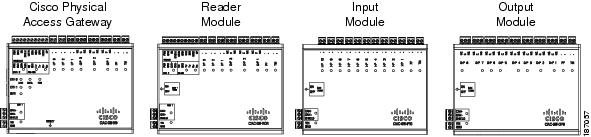
Table 1-1
•
•
•
•
•
•
•
•
•
•
•
•
•
•
•
•
•
•
•
•
•
•
•
•
•
•
1 The modules are connected using the CAN1 interface. The CAN2 interface is not supported in this release.
2 A supervised input supports four states: normal, alarm, open and short. An unsupervised input only indicates normal or alarm.
Main Features of the Cisco Physical Access Control Modules
CAN Bus Connections for Optional Modules
The optional modules are connected to a Cisco Physical Access Gateway using a CAN bus connection, as shown in Figure 1-5.
Figure 1-5 CAN Bus Wiring
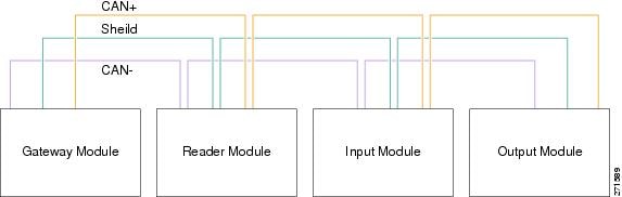
The CAN bus must adhere to the following rules:
•
•
–
–
–
•
Related Documentation
See the following chapters for instructions to install the modules and related equipment:
•
•
•
•
Installation and Configuration Summary
The following steps are an example of the main installation and configuration tasks for a Cisco Physical Access Control system. The exact procedure and order of installation for your system may vary.
Step 1
Step 2
Step 3
Step 4
Step 5
Note
Step 6
https://192.168.1.42. This URL opens the web-based configuration page.
Note
https://. This connects your browser to the secure URL.
Step 7
default username: gwadmin
default password: gwadmin
Step 8
Step 9
Step 10
Step 11
Power Options and Requirements
This section includes the following information:
•
•
Power Options
Table 1-2 summarizes the power options for each module. The Cisco Physical Access Gateway supports Power over Ethernet (PoE) and DC power. All other modules support DC power only.
•
•
Current Draw Requirements
Each Cisco Physical Access Control module requires a minimum amount of available power, as described in Table 1-3. The current draw requirements listed in Table 1-3 account for inefficiencies in power supplies and are to be used for power budgeting. The requirements do not represent actual power usage.
Installing Surge Suppressors on Output Device Connections
Install a surge suppressor between all output devices and the Gateway, Reader, or Output modules to protect the devices from power surges. Use one of the following methods:
•
•
Figure 1-6 Sample Surge Suppressor Installation

Connect Reader Devices with Module Power Off
Disconnect power from the Gateway or Reader module before connecting reader devices to the modules. Connecting a reader device when the modules are powered can cause the Gateway or Reader module to malfunction.
Mounting a Gateway or Optional Module
Each Cisco Physical Access Gateway and optional module includes two mounting brackets and four screws to mount the Gateway to the wall.
Wall Mounting a Gateway or Optional Module
Figure 1-7 shows the three options for attaching the included wall-mount brackets to a module.
Figure 1-7 Three Options for Installing Wall Mount Brackets
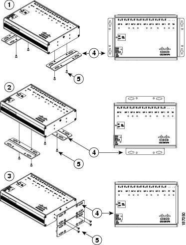
The following items are shown in Figure 1-7:
Option 1: Bottom end mounting
Mounting Brackets (included)
Option 2: Bottom side mounting
Screws
Option 3: Side mounting
Wall Mount Installation Kit Contents
Each module includes a wall mount installation kit that contains the following:
Table 1-4 Wall Mount Installation Kit Contents
Wall Mount brackets
2
Screws
8
 Feedback
Contact Cisco
- Open a Support Case

- (Requires a Cisco Service Contract)
This Document Applies to These Products
- Collaboration Endpoints - Retired Products
- Conferencing - Retired Products
- Contact Center - Retired Products
- Optical Networking - Retired Products
- Routers - Retired Products
- Security - Retired Products
- Servers - Unified Computing (UCS) Retired Products
- Storage Networking Retired Products
- Switches - Retired Products
- Video - Retired Products
- Wireless - Retired Products