Table Of Contents
Installing and Configuring the Cisco Physical Access Gateway
Physical Overview and Port Description
Installing the Cisco Physical Access Gateway
Configuring and Managing the Gateway Using a Direct Connection
Connecting a PC to the Gateway
Log On to the Gateway Administration Tool
Entering the Gateway Network Settings
Upgrading the Gateway Firmware Using a Direct Connection
Displaying Serial Numbers and Other Information
Configuring the Gateway Using Cisco Physical Access Manager
Resetting the Cisco Physical Access Gateway
Hard Reset (Restore Factory Defaults)
Installing and Configuring the Cisco Physical Access Gateway
Contents
This chapter includes the following information:
•Physical Overview and Port Description
•Installing the Cisco Physical Access Gateway
•Configuring and Managing the Gateway Using a Direct Connection
–Connecting a PC to the Gateway
–Entering the Gateway Network Settings
–Upgrading the Gateway Firmware Using a Direct Connection
–Displaying Serial Numbers and Other Information
•Configuring the Gateway Using Cisco Physical Access Manager
•Resetting the Cisco Physical Access Gateway
Overview
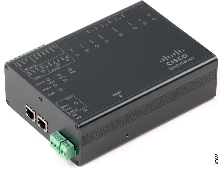
The Cisco Physical Access Gateway (Figure 2-1) is installed near each door to provide access control and connections for card readers, door locks and other input and output devices. The Gateway is connected to the Cisco Physical Access Manager using an Ethernet connection to the IP network. Power is supplied through a Power over Ethernet (PoE) connection, or using a DC power source. Each Gateway includes connections for up to two Weigand door readers, three input devices, and three output devices. Optional expansion modules are available to add additional doors and devices to the Gateway.
Figure 2-1 Cisco Physical Access Gateway
Package Contents
Each Cisco Physical Access Gateway includes the following:
•Six End-Of-Line (EOL) 1K termination resistors (used for supervised input interfaces)
•Two mounting brackets, with 4 screws for each bracket
•Regulatory compliance and safety information
•Quick Start guide
•Connector plugs, including the following:
Physical Overview and Port Description
Figure 2-2 and Figure 2-3 show the location of each port, including connections for power, Ethernet, door readers and other input and output devices.
Figure 2-2 Cisco Physical Access Gateway Ports and Connectors: Side View
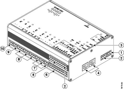
Figure 2-3 Cisco Physical Access Gateway Ports and Connectors: Top View
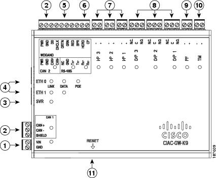
The following items are shown in Figure 2-2 and Figure 2-3:
Type Description 1Power
Two-pin connector for Voltage In (VIN) and Ground (GND) to connect a 12 to 24 VDC external power source.
2CAN
A three-wire CAN bus is used to connect additional modules, including the Cisco Reader Module, Cisco Input Module, and Cisco Output Module.
Note Modules are connected using the CAN1 interface. The CAN2 interface is not supported in this release.
3SVR (Server)
When the LED is steady green, the Gateway is connected to a Cisco PAM appliance.
4Fast Ethernet interfaces
There are two 10/100 BASE-TX RJ-45 connectors:
•ETH 0: connects the Gateway to the network. ETH 0 also supports Power over Ethernet (PoE) for the device (optional).
•ETH 1: connects the device to a PC to access the device configuration web page.
5Serial interface
The RS-485 interface is not supported in this release.
6Weigand interface
This interface can be configured as the following:
•One 10-pin Weigand/clock and data reader interface to connect a single door reader.
•Two 5-pin Weigand/clock and data interfaces to connect two door readers (for installations where a 5-pin interface is sufficient).
Note Disconnect power from the Gateway or Reader module before connecting reader devices to the modules. Connecting a reader device when the modules are powered can cause the Gateway or Reader module to malfunction.
7Input interfaces
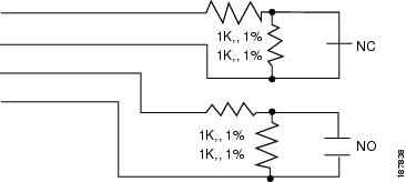
Three input interfaces used to sense the contact closure. Each input can be configured as supervised or unsupervised and can be configured to sense a Normally Open (NO) or Normally Closed (NC) contact.
•An unsupervised input senses a simple contact closure state, including Normal or Alarm. When connected to open contacts, the terminal voltage range is 4V to 5V. For closed contacts, the voltage range is 0V to 0.7V.
•A supervised input senses four contact states, including Normal, Alarm, Open and Short. These inputs require 1K End-Of-Line (EOL) termination resistors installed at the contacts (two resistors are included in the accessory kits for each Input port).
8Output interfaces
Three Form C (5A @ 30V) relay output interfaces. Each output connection can be configured as either Normally Closed (NC) or Normally Open (NO).
•C & NO connection: The relay is normally open. The circuit is closed when triggered.
•C & NC connection: The relay is normally closed. The circuit is opened when triggered.
Notes:
•Install surge protection between the output device and the Cisco PAM module, as described in Installing Surge Suppressors on Output Device Connections, page 1-11.
•Common (C) is always used, and either NC or NO is used to complete the connection.
•All Generic Output devices installed in Cisco PAM systems prior to release 1.1.0, were connected to the Gateway, Reader, or Output modules with the wiring reversed. If upgrading to Cisco PAM release 1.1.0 from an earlier release, disconnect all Generic Output devices and do the following:
–Connect Normally Open devices to the N.O. and C connectors on the Gateway, Reader, or Output module.
–Connect Normally Closed devices to the N.C. and C connectors on the Gateway, Reader, or Output module.
9PF
Power fail input: an unsupervised input that raises a "power fail" alarm when the circuit is open. Can be configured as an additional unsupervised port. An unsupervised input indicates only normal or alarm. The corresponding LED is red when circuit is open (when no input is connected).
10TM
Tamper input: an unsupervised input that raises a "tamper" alarm when the circuit is open. Can be configured as an additional unsupervised port. An unsupervised input indicates only normal or alarm. The corresponding LED is red when circuit is open (when no input is connected).
11Reset
Resets the device. See Resetting the Cisco Physical Access Gateway for more information.
LED Status
Table 2-1 describes the Gateway module status LEDs:
Installing the Cisco Physical Access Gateway
Before You Begin
Before you install a Cisco Physical Access Gateway, verify the following:
•Verify that the module has access to a power source. See Power Options and Requirements, page 1-10 for more information.
•Verify that you have the necessary mounting brackets or other hardware. See Mounting a Gateway or Optional Module, page 1-12.
Installation Procedure
To install the Cisco Physical Access Gateway, perform the following procedure:
Step 1 Mount the Gateway to a wall. See Mounting a Gateway or Optional Module, page 1-12 for more information.
Step 2 Connect the Gateway to a power source.
•If using a DC power source, insert a two-pin connector plug into the DC power port (Figure 2-4), and connect the Voltage In (VIN) and ground (GND) wires.
•If using PoE, connect an Ethernet cable from the IP network to the ETH0 port (Figure 2-4).
See Power Options and Requirements, page 1-10 for more information.
Figure 2-4 Power Connections for the Cisco Physical Access Gateway
The following items are shown in Figure 2-4:
Step 3 Connect one or two door reader devices to the Weigand interface using one of the following configurations:
•Connect a single door reader using all 10 Weigand interface pins.
•Connect one or two door readers using 5-pin Weigand interface connections (for installations where a 5-pin interface is sufficient).
Figure 2-5 shows the location of the Weigand interface connections.
Table 2-2 describes the connections for 10-pin and 5-pin reader interface connections. The wire connectors from the reader device are shown in parentheses. If attaching a second reader, use the alternative connections shown in the column on the far right.
Figure 2-5 Weigand Interface on the Gateway and Reader Modules
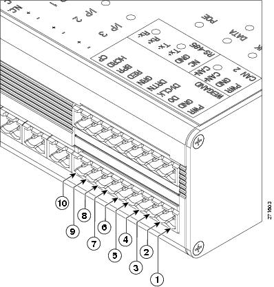
Table 2-2 Weigand Reader Wiring for 10 or 5 Pin Connections
Chassis Label Description One Reader10 Wire Connection First Reader in a5 Wire Connection Second Reader in a5 Wire Connection 1PWR
+12v
PWR (red) 1
PWR (red)
PWR (red)
2GND
Ground
GND (black)
GND (black)
GND (black)
3D0
Data 0
D0 (green)
D0 (green)
----------
4D1/CLCK
Data 1
D1/CLCK (white)
D1/CLCK (white)
----------
5DRTN
Shield
DRTN (shield)
DRTN (shield)
DRTN (shield)
6GRN
Output 2
GRN (orange)
GRN (orange)
----------
7RED
Output
RED (brown)
---------- 3
GRN (orange)
8BPR
Output (Beeper)
BPR (yellow) (yellow)
----------
----------
9HCRD
Hold Control
HCRD (blue)
----------
D1/CLCK (white)
10CP
Card Present
CP (purple)
----------
D0 (green)
1 Wire colors are shown in parentheses.
2 Outputs show the LED color and reader wire color (in parentheses). For example, "GRN (orange)" supports a green LED. Attach the orange wire from the reader device.
3 ---------- means the wire slot is not used.
Step 4 Connect input devices to the Gateway:
a. Insert two-pin connector plugs into the input ports (see Figure 2-7).
b. (Optional, for supervised input connections only). Install two End-Of-Line (EOL) 1K termination resistors in each supervised input interface (one terminator in each connector). Figure 2-6 shows the terminator installation for a Normally Closed (NC) and Normally Open (NO) input connection.
Figure 2-6 Input Connections: Cisco Physical Access Gateway and Reader Module
c. Connect the wires from the input devices (see Figure 2-7).
Note Each of the input connections can be configured as supervised or unsupervised. The tamper and power fail inputs can be configured as additional unsupervised ports. A supervised input supports four states: normal, alarm, open and short. An unsupervised input indicates only normal or alarm.
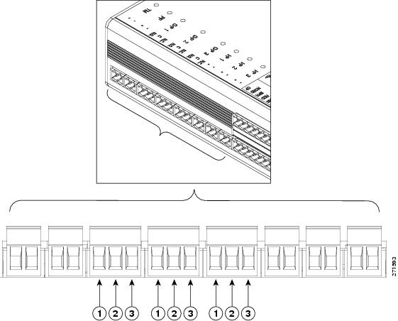
Figure 2-7 Input Connections: Cisco Physical Access Gateway and Reader Module
The following items are shown in Figure 2-7:
Step 5 Connect output devices to the Gateway (Figure 2-8). Each of the three Form C (5A @ 30V) relay output connections can be configured as either Normally Closed (NC) or Normally Open (NO).
a. Insert three-pin connector plugs into the output ports.
b. Connect the wires from the output devices.
–Common (C) is always used, and either NC or NO is used to complete the connection.
–If the relay is normally open, use the C & NO connections. The circuit is closed when triggered.
–If the relay is normally closed, use the C & NC connections. The circuit is opened when triggered.
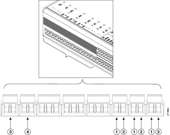
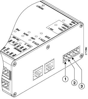
Figure 2-8 Output Connections: Cisco Physical Access Gateway and Reader Module
The following items are shown in Figure 2-8:
Step 6 Connect optional expansion modules to the Gateway, if necessary:
a. Insert a three-pin connector plug into the CAN1 port, as shown in Figure 2-9.
b. Connect the CAN wires to the CAN bus, as shown in Figure 2-10.
c. On the last device in the CAN bus, set the CAN terminator switch to ON. The CAN terminator switch in included on the Reader, Input and Output modules only (the Gateway is always the first device in the CAN bus). Set the terminator switch to OFF for all other modules in the CAN bus.
Note Modules are connected using the CAN1 interface. The CAN2 interface is not supported in this release.
Figure 2-9 CAN1 Connections: Cisco Physical Access Gateway and Reader Module
The following items are shown in Figure 2-9:
Connection Description 1CAN+
Connects to the positive terminal of the CAN bus.
2CAN-
Connects to the negative terminal of the CAN bus.
3Shield
Connects to GND and/or Shield.
Figure 2-10 CAN Bus Wiring
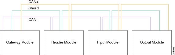
Note On the last device in the CAN bus, set the CAN terminator switch to ON. The CAN terminator switch in included on the Reader, Input and Output modules only (the Gateway is always the first device in the CAN bus).
Step 7 Connect the Gateway to the IP network by connecting an Ethernet cable to the ETH0 port, as shown in Figure 2-11.
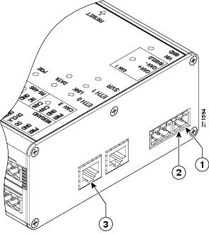
Figure 2-11 ETH 0 Ethernet Connection for the Cisco Physical Access Gateway
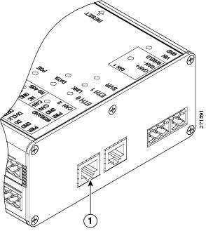
The following items are shown in Figure 2-11:
Port Description 1ETH0
Ethernet port for connecting the Gateway to the IP network.
Note The ETH0 connection can also be used for Power over Ethernet.
Note The ETH1 port is used to connect a PC to the Gateway for configuration and monitoring. See Configuring and Managing the Gateway Using a Direct Connection for more information.
Step 8 Continue to Configuring the Gateway Using Cisco Physical Access Manager.
Configuring and Managing the Gateway Using a Direct Connection
To enable the Gateway communication with the Cisco PAM appliance, connect a PC to the ETH1 port and use a web browser to enter basic network settings, as described in this section. You can also use the web administration tool to perform basic administration and monitoring tasks, such as upgrading the module firmware or displaying the module serial number.
This section includes the following information:
•Connecting a PC to the Gateway
•Entering the Gateway Network Settings
•Upgrading the Gateway Firmware Using a Direct Connection
•Displaying Serial Numbers and Other Information
Connecting a PC to the Gateway
To enter the initial Gateway settings or perform other administration tasks, connect a PC to the Gateway Eth1 port and use a web browser to access the administration pages, as described in the following steps:
•Log On to the Gateway Administration Tool
Before You Begin
To configure a Cisco Physical Access Gateway, you need the following:
•A PC and web browser.
The Cisco Physical Access Gateway supports Internet Explorer 6.0 and higher.•A Ethernet cable to connect your PC to the Gateway.
Cross-over and straight-through cables are supported.•Your PC must be configured to connect to the 192.168.1.0 network using Ethernet. Use any static host address on the network other than 192.168.1.42.
•Power connected to the Cisco Physical Access Gateway.
See Installing the Cisco Physical Access Gateway for more information.In addition, gather the following information:
•The IP Address of the Cisco PAM appliance.
•You can use a DHCP server to assign an IP address for the Gateway.
If a DHCP server is not used, gather the Cisco Physical Access Gateway IP address, IP gateway, subnet mask.•The domain name server (DNS) for the Gateway if names (not IP addresses) are used for the NTP or CPAM addresses.
Log On to the Gateway Administration Tool
Step 1 Connect an Ethernet cable from a PC to the ETH1 interface on the Gateway module.
•See Physical Overview and Port Description for the port location.
•Be sure to connect your PC to the ETH1 port. The ETH0 port is used for network communication.
•Your PC must be configured to connect to the 192.168.1.0 network using Ethernet. Use any static host address on the network other than 192.168.1.42.
Step 2 Open a web browser on your PC and enter
https://192.168.1.42
. to access the web-based administration pages.Step 3 Enter the default username and password (Figure 2-12).
default username: gwadmin
default password: gwadmin
Figure 2-12 Login Screen for the Cisco Physical Access Gateway
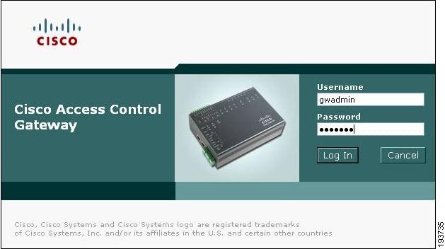
The web administration pages appear, and are described in the following sections.
Entering the Gateway Network Settings
Enter the network settings to enable IP communication between the Gateway and the Cisco PAM appliance. Network settings include the following:
•Eth0 Configuration for IP network connectivity with the Cisco PAM appliance.
•DNS Configuration if names (not IP addresses) are used for the NTP or CPAM addresses.
•Cisco PAM Configuration to define the IP address and port of the Cisco PAM appliance used to manage the Gateway.
Tip Gateway modules can be added to the IP network before or after the full module configuration is entered in Cisco PAM. For more information, see the Cisco Physical Access Manager User Guide.
Complete the following steps for each Gateway in the system.
Enter the Network settings, as shown in Figure 2-13.
Figure 2-13 Network Settings for the Cisco Physical Access Gateway
Step 1 Enter the ETH0 Configuration settings. The ETH0 port is used for network communications with the Cisco PAM appliance.
a. If a Dynamic Host Configuration Protocol (DHCP) server is configured on your IP network, select the DHCP check box for ETH0 to automatically configure the required IP network settings, including IP address, Subnet Mask, and Gateway. The DHCP check box is selected by default.
b. (Optional) If a DHCP server is not used to assign IP address settings, enter the following information in the ETH0 fields:
–IP address: Enter the IP address of the Cisco Physical Access Gateway.
–Subnet Mask: Enter the subnet mask.
–Gateway: Enter the IP gateway address.
Step 2 (Optional) Enter the DNS Server address if names (not IP addresses) are used for the CPAM address.
Step 3 Enter the Cisco PAM Configuration:
a. Enter the Cisco PAM IP address (IP address or name) to enable Gateway communication with the appliance.
b. Enter the port number for the Cisco PAM appliance. The port number must be greater than 1024 and less 65535. The default is 8020.
Tip DHCP can also be configured to supply the Gateway with the IP address of the Cisco PAM appliance by configuring option 150 in the DHCP response. The Cisco PAM appliance TCP port number can be provided by DHCP option 151 of the DHCP response.
c. Enable SSL: The secure socket layer (SSL) is enabled for secure communication between the Gateway and Cisco PAM appliance by default. If necessary SSL can be disabled by deselecting the Enable SSL check box.
Note SSL is enabled or disabled for all Gateways and the Cisco PAM appliance. Cisco Systems recommends that SSL always be enabled to ensure secure communications. If the SSL settings are changed, you must reset all Gateways and the Cisco PAM appliance.
Step 4 Click Save to save the settings. Wait until the Gateway resets and the web browser displays the screen Network Settings Applied.
Note Changes do not take effect until saved.
Step 5 Repeat these steps for each Gateway in the system.
Step 6 Perform additional configuration, verification, and monitoring tasks as described in the Cisco Physical Access Manager User Guide.
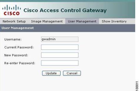
Changing the User Password
To change the password used to access the Gateway, do the following:
Tip You can also change the password for one or more Gateways using the Cisco PAM desktop software. See the Cisco Physical Access Manager User Guide for more information.
Step 1 Select the User Management tab, as shown in Figure 2-14.
Figure 2-14 User Management for the Cisco Physical Access Gateway
Step 2 Enter the Current Password.
Step 3 Enter the New Password.
Step 4 Re-enter the new password to verify the setting.
Step 5 Click Update to save the changes.
Note The Username cannot be changed.
Tip To reset the device to the default password, see Hard Reset (Restore Factory Defaults). You can also change the password using the Cisco PAM desktop software.
Upgrading the Gateway Firmware Using a Direct Connection
To upgrade the Gateway firmware from a PC directly connected to the module, do the following:
Note For instructions to upgrade firmware from the Cisco PAM appliance. See the Cisco Physical Access Manager User Guide.
Step 1 Log on to the Gateway administration tool, as described in Connecting a PC to the Gateway.
Step 2 Select the Image Management tab, as shown in Figure 2-15.
Figure 2-15 Image Management for the Cisco Physical Access Gateway
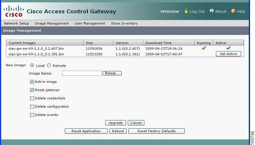
Step 3 Determine the active and running firmware images:
The Image Management window displays all firmware images loaded on the Gateway. The running image is the firmware currently operating the Gateway module. The active image is the image that will become the running image when the Gateway module is reset. The table displays the images currently loaded on the module:
•Current Image: displays a list of the firmware images currently loaded on the Gateway module.
•Running Image: the image operating the Gateway. A check appears under the Running column.
•Active Image: the image set as the active image. A check appears under the Active column.
Step 4 Upload a new firmware image from a file located on a local disk or on a remote TFTP server:
Tip You can also select an exisitng image. Click Set Active to define the new active image (see Figure 2-15), and then reset the Gateway. The new active image becomes the running image only after the Gateway is reset. See Soft Reset (Powercycle)
Option 1: Local Disk
To upload a firmware file from a local on the connected PC:
a. Select the Local radio button under New Image.
b. Click the Browse button to navigate the local drive and select a file. The file appears in the top Image Name field. You can also enter the directory path and filename manually.
Option 2: Remote TFTP Server
To upload a firmware file from a remote TFTP server:
a. Select the Remote radio button under New Image.
b. Enter the TFTP Server IP address.
c. Enter the directory Path on the TFTP server for the firmware image. Be sure the path and filename are valid. The administration tool does not verify remote server paths.
Tip The directory path and filename for the remote image displays in the second Image Name field. You can also enter the path and filename manually.
d. Select the options that will occur after the image is loaded to the Gateway:
Note When upgrading Gateway firmware images to release 1.1.0 from any earlier release, select all available options.
–Active image: (checked by default) make the firmware file new active image.
–Reset Gateway: (checked by default) perform a soft reset to powercycle the module. See Soft Reset (Powercycle) for more information. Changes to the active image are applied only after the Gateway is reset.
–Delete credentials: delete the credential data stored on the Gateway.
–Delete configuration: delete the module configuration. The configuration is automatically reloaded when the module established communication with the Cisco PAM appliance.
–Delete events: delete all events stored on the module.
Step 5 Click Upgrade to copy the firmware image to the Gateway module and perform the selected options (if any). When all options are selected, wait approximately 10-15 minutes for the firmware upgrade to complete .
Note The Gateway must be reset to enable the new active image.
Displaying Serial Numbers and Other Information
Use the Show Inventory window to display the module serial number and other information, such as the module serial number.
Step 1 Log on to the Gateway administration tool, as described in Connecting a PC to the Gateway.
Step 2 Select the Show Inventory tab, as shown in Figure 2-16.
Figure 2-16 Show Inventory Window for the Cisco Physical Access Gateway
Tip The serial number is also displayed on the back of the module. To view the serial number in Cisco PAM, open the Hardware module device view, right-click on the Gateway Controller, and select Edit to view the module properties.
Configuring the Gateway Using Cisco Physical Access Manager
After the initial Gateway configuration is complete, use the The Cisco Physical Access Manager appliance for advanced configuration of all Gateways and other components in the system.
Tip You can configure the Gateway modules in Cisco PAM before or after they are added to the IP network. For more information, see the Cisco Physical Access Manager User Guide.
Resetting the Cisco Physical Access Gateway
Reset the Gateway to powercycle the module, restore the factory settings, or delete the stored logs and other data. The effect of the restart depends on the type of restart your perform, as described in the following sections. You can reset the module using the physical button on the side of the module, or in software using either the web administration tool or the Hardware device view in Cisco PAM.
•Hard Reset (Restore Factory Defaults)
Note See Physical Overview and Port Description for the location of the Reset button.
Tip You can also use the to reset the device or restore the factory default settings.
Soft Reset (Powercycle)
Use the soft reset to powercycle the Cisco Physical Access Gateway. A soft reset reloads the device firmware to clear any software issues, but does not impact stored data. The password, logs and other information are retained.
Use one of the following methods to perform a soft reset:
•Hardware reset button: Press and release the reset button once. See Figure 2-2 ("Cisco Physical Access Gateway Ports and Connectors: Side View").
•Gateway web administration tool: Follow the instructions in Configuring and Managing the Gateway Using a Direct Connection to connect a PC to the Gateway, and click the Reset button at the bottom of the screen.
•Cisco PAM: Open the Hardware module from the Doors menu and right-click on the Gateway Controller (blue icon). Select Reset from the menu.
Hard Reset (Restore Factory Defaults)
A hard reset deletes all information on the device, including log and event data, and resets the password and all other configurations to the factory default. Any custom configurations previously entered on the device are removed.
Note the following:
•Allow five to 10 minutes for the hard reset erase operation to complete.
•Do not disconnect power from the module until the hard reset erase process is complete. Loss of power during a hard reset can result in equipment malfunction.
•The SVR LED flashes throughout the erase operation.
•The module reboots with the existing firmware image after the hard reset is complete.
Use one of the following methods to perform a hard reset:
•Hardware reset button: Press reset button three times in succession. See Figure 2-2 ("Cisco Physical Access Gateway Ports and Connectors: Side View").
•Gateway web administration tool: Follow the instructions in Configuring and Managing the Gateway Using a Direct Connection to connect a PC to the Gateway, and click the Restore Factory Defaults button at the bottom of the screen.