Configuring Bidirectional Forwarding Detection on Cisco IOS XR Software
Available Languages
Table Of Contents
Configuring Bidirectional Forwarding Detection on Cisco IOS XR Software
Prerequisites for Configuring BFD
Restrictions for Configuring BFD
Differences in BFD in Cisco IOS XR Software and Cisco IOS Software
BFD Source and Destination Ports
BFD Packet Intervals and Failure Detection
Priority Settings for BFD Packets
BFD Over Member Links on Link Bundles
Overview of BFD State Change Behavior on Member Links and Bundle Status
Configuring BFD Under a Dynamic Routing Protocol or Using a Static Route
Enabling BFD on a BGP Neighbor
Enabling BFD for OSPF on an Interface
Enabling BFD on a Static Route
Configuring BFD on Bundle Member Links
Specifying the BFD Destination Address on a Bundle
Enabling BFD Sessions on Bundle Members
Configuring the Minimum Thresholds for Maintaining an Active Bundle
Configuring BFD Packet Transmission Intervals and Failure Detection Times on a Bundle
Configuring Allowable Delays for BFD State Change Notifications Using Timers on a Bundle
Enabling Echo Mode to Test the Forwarding Path to a BFD Peer
Overriding the Default Echo Packet Source Address
Specifying the Echo Packet Source Address Globally for BFD
Specifying the Echo Packet Source Address on an Individual Interface or Bundle
Configuring BFD Session Teardown Based on Echo Latency Detection
Delaying BFD Session Startup Until Verification of Echo Path and Latency
Disabling Echo Mode on a Router
Disabling Echo Mode on an Individual Interface
Minimizing BFD Session Flapping Using BFD Dampening
Clearing and Displaying BFD Counters
Configuration Examples for Configuring BFD
BFD Over Static Routes: Example
000000000000000000000000BFD on Bundle Member Links: Examples
Echo Packet Source Address: Examples
Echo Latency Detection: Examples
Echo Startup Validation: Examples
BFD Echo Mode Disable: Examples
BFD Peers on Routers Running Cisco IOS and Cisco IOS XR Software: Example
Configuring Bidirectional Forwarding Detection on Cisco IOS XR Software
This module describes the configuration of bidirectional forwarding detection (BFD) on the Cisco XR 12000 Series Router.
Bidirectional forwarding detection (BFD) provides low-overhead, short-duration detection of failures in the path between adjacent forwarding engines. BFD allows a single mechanism to be used for failure detection over any media and at any protocol layer, with a wide range of detection times and overhead. The fast detection of failures provides immediate reaction to failure in the event of a failed link or neighbor.
Feature History for Configuring Bidirectional Forwarding Detection on Cisco IOS XR Software
Contents
•
Prerequisites for Configuring BFD
•
•
Prerequisites for Configuring BFD
You must be in a user group associated with a task group that includes the proper task IDs. The command reference guides include the task IDs required for each command. If you suspect user group assignment is preventing you from using a command, contact your AAA administrator for assistance.
The following prerequisites are required to implement BFD:
•
•
•
–
–
–
•
•
•
–
–
Link Aggregation Control Protocol (LACP) Distributing state is reached, -Or-
EtherChannel or POS Channel is configured, -Or-
Hot Standby and LACP Collecting state is reached.
Restrictions for Configuring BFD
The following restrictions apply to BFD:
•
•
–
–
–
•
•
•
Information About BFD
To configure BFD, you should understand the following concepts:
•
•
Differences in BFD in Cisco IOS XR Software and Cisco IOS Software
If you are already familiar with BFD configuration in Cisco IOS software, be sure to consider the following differences in BFD configuration in the Cisco IOS XR software implementation:
•
•
•
•
BFD Modes of Operation
Cisco IOS XR software supports the asynchronous mode of operation only, with or without using echo packets. Asynchronous mode without echo will engage various pieces of packet switching paths on local and remote systems. However, asynchronous mode with echo is usually known to provide slightly wider test coverage as echo packets are self-destined packets which traverse same packet switching paths as normal traffic on the remote system.
BFD echo mode is enabled by default for the following interfaces:
•
•
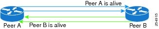
When BFD is running asynchronously without echo packets (Figure 1), the following occurs:
•
•
•
Figure 1 BFD Asynchronous Mode Without Echo Packets
When BFD is running asynchronously with echo packets (Figure 2), the following occurs:
•
•
Figure 2 BFD Asynchronous Mode With Echo Packets
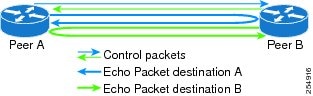
For more information about control and echo packet intervals in asynchronous mode, see the "BFD Packet Intervals and Failure Detection" section.
BFD Packet Information
This section includes the following topics:
•
•
•
BFD Source and Destination Ports
BFD payload control packets are encapsulated in UDP packets, using destination port 3784 and source port 49152. Even on shared media, like Ethernet, BFD control packets are always sent as unicast packets to the BFD peer.
Echo packets are encapsulated in UDP packets, as well, using destination port 3785 and source port 3785.
The BFD over bundle member feature increments each byte of the UDP source port on echo packets with each transmission. UDP source port ranges from 0xC0C0 to 0xFFFF. For example:
1st echo packet: 0xC0C0
2nd echo packet: 0xC1C1
3rd echo packet: 0xC2C2
The UDP source port is incremented so that sequential echo packets are hashed to deviating bundle member.
BFD Packet Intervals and Failure Detection
BFD uses configurable intervals and multipliers to specify the periods at which control and echo packets are sent in asynchronous mode and their corresponding failure detection.
There are differences in how these intervals and failure detection times are implemented for BFD sessions running over physical interfaces, and BFD sessions on bundle member links.
BFD Packet Intervals on Physical Interfaces
When BFD is running over physical interfaces, echo mode is used only if the configured interval is less than two seconds.
BFD sessions running over physical interfaces when echo mode is enabled send BFD control packets at a slow rate of every two seconds. There is no need to duplicate control packet failure detection at a fast rate because BFD echo packets are already being sent at fast rates and link failures will be detected when echo packets are not received within the echo failure detection time.
BFD Packet Intervals on Bundle Member Links
On each bundle member interface, BFD asynchronous mode control packets run at user-configurable interval and multiplier values, even when echo mode is running.
However, on a bundle member interface when echo mode is enabled, BFD asynchronous mode must continue to run at a fast rate because one of the requirements of enabling BFD echo mode is that the bundle member interface is available in BFD asynchronous mode.
The maximum echo packet interval for BFD on bundle member links is the minimum of either 30 seconds or the asynchronous control packet failure detection time.
When echo mode is disabled, the behavior is the same as BFD over physical interfaces, where sessions exchange BFD control packets at the configured rate.
Control Packet Failure Detection In Asynchronous Mode
Control packet failure in asynchronous mode without echo is detected using the values of the minimum interval (bfd minimum-interval for non-bundle interfaces, and bfd address-family ipv4 minimum-interval for bundle interfaces) and multiplier (bfd multiplier for non-bundle interfaces, and bfd address-family ipv4 multiplier for bundle interfaces) commands.
For control packet failure detection, the local multiplier value is sent to the neighbor. A failure detection timer is started based on (I x M), where I is the negotiated interval, and M is the multiplier provided by the remote end.
Whenever a valid control packet is received from the neighbor, the failure detection timer is reset. If a valid control packet is not received from the neighbor within the time period (I x M), then the failure detection timer is triggered, and the neighbor is declared down.
Echo Packet Failure Detection In Asynchronous Mode
The standard echo failure detection scheme is done through a counter that is based on the value of the bfd multiplier command on non-bundle interfaces, and the value of the bfd address-family ipv4 multiplier command for bundle interfaces.
This counter is incremented each time the system sends an echo packet, and is reset to zero whenever any echo packet is received, regardless of the order that the packet was sent in the echo packet stream.
Under ideal conditions, this means that BFD generally detects echo failures that exceed the period of time (I x M) or (I x M x M) for bundle interfaces, where:
•
•
So, if the system transmits one additional echo packet beyond the multiplier count without receipt of any echo packets, echo failure is detected and the neighbor is declared down (See Example 2).
However, this standard echo failure detection does not address latency between transmission and receipt of any specific echo packet, which can build beyond (I x M) over the course of the BFD session. In this case, BFD will not declare a neighbor down as long as any echo packet continues to be received within the multiplier window and resets the counter to zero. Beginning in Cisco IOS XR 4.0.1, you can configure BFD to measure this latency for non-bundle interfaces. For more information, see Example 3 and the "Echo Packet Latency" section.
Echo Failure Detection Examples
This section provides examples of several scenarios of standard echo packet processing and failure detection without configuration of latency detection for non-bundle interfaces. In these examples, consider an interval of 50 ms and a multiplier of 3.

Note
Example 1
The following example shows an ideal case where each echo packet is returned before the next echo is transmitted. In this case, the counter increments to 1 and is returned to 0 before the next echo is sent and no echo failure occurs. As long as the roundtip delay for echo packets in the session is less than the minimum interval, this scenario occurs:
Time (T): Echo#1 TX (count = 1)T + 1 ms: Echo#1 RX (count = 0)T + 50 ms: Echo#2 TX (count = 1)T + 51 ms: Echo#2 RX (count = 0)T + 100 ms: Echo#3 TX (count = 1)T + 101 ms: Echo#3 RX (count = 0)T + 150 ms: Echo#4 TX (count = 1)T + 151 ms: Echo#4 RX (count = 0)Example 2
The following example shows the absence in return of any echo packets. After the transmission of the fourth echo packet, the counter exceeds the multiplier value of 3 and echo failure is detected. In this case, echo failure detection occurs at the 150 ms (I x M) window:
Time (T): Echo#1 TX (count = 1)T + 50 ms: Echo#2 TX (count = 2)T + 100 ms: Echo#3 TX (count = 3)T + 150 ms: Echo#4 TX (count = 4 -> echo failureExample 3
The following example shows an example of how roundtrip latency can build beyond (I x M) for any
particular echo packet over the course of a BFD session using the standard echo failure detection, but
latency between return of echo packets overall in the session never exceeds the (I x M) window and
the counter never exceeds the multiplier, so the neighbor is not declared down.
Note
Time (T): Echo#1 TX (count = 1)T + 1 ms: Echo#1 RX (count = 0)T + 50 ms: Echo#2 TX (count = 1)T + 51 ms: Echo#2 RX (count = 0)T + 100 ms: Echo#3 TX (count = 1)T + 150 ms: Echo#4 TX (count = 2)T + 151 ms: Echo#3 RX (count = 0; ~50 ms roundtrip latency)T + 200 ms: Echo#5 TX (count = 1)T + 250 ms: Echo#6 TX (count = 2)T + 251 ms: Echo#4 RX (count = 0; ~100 ms roundtrip latency)T + 300 ms: Echo#7 TX (count = 1)T + 350 ms: Echo#8 TX (count = 2)T + 351 ms: Echo#5 RX (count = 0; ~150 ms roundtrip latency)T + 451 ms: Echo#6 RX (count = 0; ~200 ms roundtrip latency; no failure detection)T + 501 ms: Echo#7 RX (count = 0; ~200 ms roundtrip latency; no failure detection)T + 551 ms: Echo#8 RX (count = 0; ~200 ms roundtrip latency; no failure detection)Looking at the delay between receipt of echo packets for the BFD session, observe that no latency is beyond the (I x M) window:
Echo#1 RX - Echo#2 RX: 50 msEcho#2 RX - Echo#3 RX: 100msEcho#3 RX - Echo#4 RX: 100msEcho#4 RX - Echo#5 RX: 100msEcho#5 RX - Echo#6 RX: 100msEcho#6 RX - Echo#7 RX: 50msEcho#7 RX - Echo#8 RX: 50msSummary of Packet Intervals and Failure Detection Times for BFD on Bundle Interfaces
For BFD on bundle interfaces, with a session interval I and a multiplier M, the following packet intervals and failure detection times apply for BFD asynchronous mode (Table 2):
•
•
–
–
•
Table 2 BFD Packet Intervals and Failure Detection Time Examples on Bundle Interfaces
50
3
150
150
450
75
4
300
300
1200
200
2
400
400
800
2000
3
6000
6000
18000
15000
3
45000
300001
90000
1 The maximum echo packet interval for BFD on bundle member links is the minimum of either 30 seconds or the asynchronous control packet failure detection time.
Echo Packet Latency
In Cisco IOS XR software releases prior to Cisco IOS XR 4.0.1, BFD only detects an absence of receipt of echo packets, not a specific delay for TX/RX of a particular echo packet. In some cases, receipt of BFD echo packets in general can be within their overall tolerances for failure detection and packet transmission, but a longer delay might develop over a period of time for any particular roundtrip of an echo packet (See Example 3).
Beginning in Cisco IOS XR 4.0.1, you can configure the router to detect the actual latency between transmitted and received echo packets on non-bundle interfaces and also take down the session when the latency exceeds configured thresholds for that roundtrip latency. For more information, see the "Configuring BFD Session Teardown Based on Echo Latency Detection" section.
In addition, you can verify that the echo packet path is within specified latency tolerances before starting a BFD session. With echo startup validation, an echo packet is periodically transmitted on the link while it is down to verify successful transmission within the configured latency before allowing the BFD session to change state. For more information, see the "Delaying BFD Session Startup Until Verification of Echo Path and Latency" section.
Priority Settings for BFD Packets
For all interfaces under over-subscription, the internal priority needs to be assigned to remote BFD Echo packets, so that these BFD packets are not overwhelmed by other data packets. In addition, CoS values need to be set appropriately, so that in the event of an intermediate switch, the reply back of remote BFD Echo packets are protected from all other packets in the switch.
As configured CoS values in ethernet headers may not be retained in Echo messages, CoS values must be explicitly configured in the appropriate egress QoS service policy. CoS values for BFD packets attached to a traffic class can be set using the set cos command. For more information on configuring class-based unconditional packet marking, see "Configuring Modular QoS Packet Classification" in the Cisco IOS XR Modular Quality of Service Configuration Guide for the Cisco XR 12000 Series Router.
BFD for IPv4
Cisco IOS XR software supports bidirectional forwarding detection (BFD) for IPv4.
In BFD for IPv4 single-hop connectivity, Cisco IOS XR software supports both asynchronous mode and echo mode over physical numbered Packet-over-SONET/SDH (POS) and Gigabit Ethernet links, as follows:
•
•
•
Consider the following guidelines when configuring BFD on Cisco IOS XR software:
•
•
–
–
–
–
–
–
–
–
Note
•
–
–
–
–
–
•
•
BFD Over Member Links on Link Bundles
Beginning in Cisco IOS XR Release 4.1, the BFD feature supports BFD sessions on individual physical bundle member links to monitor Layer 3 connectivity on those links, rather than just at a single bundle member as in prior releases (Figure 3).
Figure 3 BFD Sessions in Original BFD Over Bundles and Enhanced BFD Over Bundle Member Links Architectures
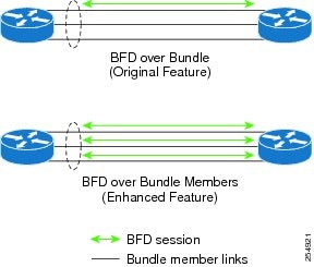
When you run BFD on link bundles, you can run an independent BFD session on each underlying physical interface that is part of that bundle.
When BFD is running on a link bundle member, the following layers of connectivity are effectively tested as part of the interface state monitoring for BFD:
•
•
•
The BFD agent on each bundle member link monitors state changes on the link. BFD agents for sessions running on bundle member links communicate with a bundle manager. The bundle manager determines the state of member links and the overall availability of the bundle. The state of the member links contributes to the overall state of the bundle based on the threshold of minimum active links or minimum active bandwidth that is configured for that bundle.
Overview of BFD State Change Behavior on Member Links and Bundle Status
This section describes when bundle member link states are characterized as active or down, and their effect on the overall bundle status:
•
Note
•
•
–
–
•
–
The BFD system notifies the peer on the neighbor router that the configuration is removed. The BFD session is removed from the bundle manager without affecting other bundle member interfaces or the overall bundle state.
–
Removing a member link from a bundle causes the bundle member to be removed ungracefully. The BFD session is deleted and BFD on the neighboring router marks the session DOWN rather than NBR_CONFIG_DOWN.
•
–
The BFD system notifies the bundle manager that the BFD configuration has been removed on the neighboring router and, if bfd timers nbr-unconfig is configured on the link, the timer is started. If the BFD configuration is removed on the local router before the timer expires, then the timer is stopped and the behavior is as expected for BFD configuration removal on the local router.
If the timer expires, then the behavior is the same as for a BFD session DOWN notification.
–
•
•
Whenever a member's state changes, the bundle manager determines if the number of active members is less than the minimum number of active links threshold. If so, then the bundle is placed, or remains, in DOWN state. Once the number of active links reaches the minimum threshold then the bundle returns to UP state.
•
•
•
Note
How to Configure BFD
This section includes the following procedures:
•
•
•
•
•
•
•
•
•
•
BFD Configuration Guidelines
Before you configure BFD, consider the following guidelines:
•
•
•
–
•
•
–
–

Caution
To enable or disable IPv4 uRPF checking on an IPv4 interface, use the [no] ipv4 verify unicast source reachable-via command in interface configuration mode.
Configuring BFD Under a Dynamic Routing Protocol or Using a Static Route
To establish a BFD neighbor, complete at least one of the following procedures to configure BFD under a dynamic routing protocol or using a static route:
•
•
•
Enabling BFD on a BGP Neighbor
BFD can be enabled per neighbor, or per interface. This task describes how to enable BFD for BGP on a neighbor router. To enable BFD per interface, use the steps in the "Enabling BFD for OSPF on an Interface" section.
Note
SUMMARY STEPS
1.
2.
3.
4.
5.
6.
7.
8.
or
commitDETAILED STEPS
Enabling BFD for OSPF on an Interface
The following procedures describe how to configure BFD for Open Shortest Path First (OSPF) on an interface. The steps in the procedure are common to the steps for configuring BFD on IS-IS and MPLS-TE; only the command mode differs.
Note
SUMMARY STEPS
1.
2.
3.
4.
5.
6.
7.
8.
or
commit9.
DETAILED STEPS
Enabling BFD on a Static Route
The following procedure describes how to enable BFD on a static route.
SUMMARY STEPS
1.
2.
3.
4.
5.
6.
or
commitDETAILED STEPS
Configuring BFD on Bundle Member Links
To configure BFD on bundle member links, complete the following procedures:
•
•
•
•
•
•
Prerequisites
The physical interfaces that are members of a bundle must be directly connected between peer routers without any switches in between.
Specifying the BFD Destination Address on a Bundle
To specify the BFD destination address on a bundle, complete the following steps:
SUMMARY STEPS
1.
2.
3.
4.
or
commitDETAILED STEPS
Enabling BFD Sessions on Bundle Members
To enable BFD sessions on bundle member links, complete the following steps:
SUMMARY STEPS
1.
2.
3.
4.
or
commitDETAILED STEPS
Configuring the Minimum Thresholds for Maintaining an Active Bundle
The bundle manager uses two configurable minimum thresholds to determine whether a bundle can be brought up or remain up, or is down, based on the state of its member links.
•
•
Whenever a member's state changes, the bundle manager determines if the number of active members or available bandwidth is less than the minimum. If so, then the bundle is placed, or remains, in DOWN state. Once the number of active links or available bandwidth reaches one of the minimum thresholds, then the bundle returns to UP state.
To configure minimum bundle thresholds, complete the following steps:
SUMMARY STEPS
1.
2.
3.
4.
5.
or
commitDETAILED STEPS
Configuring BFD Packet Transmission Intervals and Failure Detection Times on a Bundle
BFD asynchronous packet intervals and failure detection times for BFD sessions on bundle member links are configured using a combination of the bfd address-family ipv4 minimum-interval and bfd address-family ipv4 multiplier interface configuration commands on a bundle.
The BFD control packet interval is configured directly using the bfd address-family ipv4 minimum-interval command. The BFD echo packet interval and all failure detection times are determined by a combination of the interval and multiplier values in these commands. For more information see the "BFD Packet Intervals and Failure Detection" section.
To configure the minimum transmission interval and failure detection times for BFD asynchronous mode control and echo packets on bundle member links, complete the following steps:
SUMMARY STEPS
1.
2.
3.
4.
5.
or
commitDETAILED STEPS
Configuring Allowable Delays for BFD State Change Notifications Using Timers on a Bundle
The BFD system supports two configurable timers to allow for delays in receipt of BFD SCNs from peers before declaring a BFD session on a link bundle member down:
•
•
For more information about how these timers work and other BFD state change behavior, see the "Overview of BFD State Change Behavior on Member Links and Bundle Status" section.
To configure the timers that allow for delays in receipt of BFD SCNs from peers, complete the following steps:
SUMMARY STEPS
1.
2.
3.
4.
5.
or
commitDETAILED STEPS
Enabling Echo Mode to Test the Forwarding Path to a BFD Peer
BFD echo mode is enabled by default for the following interfaces:
•
•
Note
Overriding the Default Echo Packet Source Address
If you do not specify an echo packet source address, then BFD uses the IP address of the output interface as the default source address for an echo packet.
In Cisco IOS XR releases before 3.9.0, we recommend that you configure the local router ID using the router-id command to change the default IP address for the echo packet source address to the adrdress specified as the router ID.
Beginning in Cisco IOS XR release 3.9.0 and later, you can use the echo ipv4 source command in BFD or interface BFD configuration mode to specify the IP address that you want to use as the echo packet source address.
You can override the default IP source address for echo packets for BFD on the entire router, or for a particular interface:
•
•
Specifying the Echo Packet Source Address Globally for BFD
To specify the echo packet source IP address globally for BFD on the router, complete the following steps:
SUMMARY STEPS
1.
2.
3.
4.
or
commitDETAILED STEPS
Specifying the Echo Packet Source Address on an Individual Interface or Bundle
To specify the echo packet source IP address on an individual BFD interface or bundle, complete the following steps:
SUMMARY STEPS
1.
2.
3.
4.
5.
or
commitDETAILED STEPS
Configuring BFD Session Teardown Based on Echo Latency Detection
Beginning in Cisco IOS XR 4.0.1, you can configure BFD sessions on non-bundle interfaces to bring down a BFD session when it exceeds the configured echo latency tolerance.
To configure BFD session teardown using echo latency detection, complete the following steps.
Prerequisites
Before you enable echo latency detection, be sure that your BFD configuration supports echo mode.
Restrictions
Echo latency detection is not supported on bundle interfaces.
SUMMARY STEPS
1.
2.
3.
4.
or
commitDETAILED STEPS
Delaying BFD Session Startup Until Verification of Echo Path and Latency
Beginning in Cisco IOS XR Release 4.0.1, you can verify that the echo packet path is working and within configured latency thresholds before starting a BFD session on non-bundle interfaces.
To configure BFD echo startup validation, complete the following steps.
Prerequisites
Before you enable echo startup validation, be sure that your BFD configuration supports echo mode.
Restrictions
Echo startup validation is not supported on bundle interfaces.
SUMMARY STEPS
1.
2.
3.
4.
or
commitDETAILED STEPS
Disabling Echo Mode
BFD does not support asynchronous operation in echo mode in certain environments. Echo mode should be disabled when using BFD for the following applications or conditions:
•
•
•
Note
You can disable echo mode for BFD on the entire router, or for a particular interface:
•
•
Disabling Echo Mode on a Router
To disable echo mode globally on the router complete the following steps:
SUMMARY STEPS
1.
2.
3.
4.
or
commitDETAILED STEPS
Disabling Echo Mode on an Individual Interface
The following procedures describe how to disable echo mode on an interface .
SUMMARY STEPS
1.
2.
3.
4.
5.
or
commitDETAILED STEPS
Minimizing BFD Session Flapping Using BFD Dampening
To configure BFD dampening to control BFD session flapping, complete the following steps.
SUMMARY STEPS
1.
2.
3.
4.
or
commitDETAILED STEPS
Clearing and Displaying BFD Counters
The following procedure describes how to display and clear BFD packet counters. You can clear packet counters for BFD sessions that are hosted on a specific node or on a specific interface.
SUMMARY STEPS
1.
2.
3.
DETAILED STEPS
Configuration Examples for Configuring BFD
This section includes the following BFD configuration examples:
•
•
•
•
•
•
•
BFD Over BGP: Example
The following example shows how to configure BFD between autonomous system 65000 and neighbor 192.168.70.24:
RP/0/0/CPU0:router# configureRP/0/0/CPU0:router(config)# router bgp 65000RP/0/0/CPU0:router(config-bgp)# bfd multiplier 2RP/0/0/CPU0:router(config-bgp)# bfd minimum-interval 20RP/0/0/CPU0:router(config-bgp)# neighbor 192.168.70.24RP/0/0/CPU0:router(config-bgp-nbr)# remote-as 2RP/0/0/CPU0:router(config-bgp-nbr)# bfd fast-detectBFD Over OSPF: Example
The following example shows how to enable BFD for OSPF on a Gigabit Ethernet interface:
RP/0/0/CPU0:router# configureRP/0/0/CPU0:router(config)# router ospf 0RP/0/0/CPU0:router(config-ospf)# area 0RP/0/0/CPU0:router(config-ospf-ar)# interface gigabitEthernet 0/3/0/1RP/0/0/CPU0:router(config-ospf-ar-if)# bfd fast-detectRP/0/0/CPU0:router(config-ospf-ar-if)# commitRP/0/0/CPU0:Dec 2 07:06:48.508 : config[65685]: %MGBL-LIBTARCFG-6-COMMIT : Configuration committed by user 'xxx'. Use 'show configuration commit changes 1000001134' to view the changes.RP/0/0/CPU0:router(config-ospf-ar-if)# endRP/0/0/CPU0:Dec 2 07:06:48.848 : config[65685]: %MGBL-SYS-5-CONFIG_I : Configured from console by labRP/0/0/CPU0:router# show run router ospfrouter ospf 0area 0interface GigabitEthernet0/3/0/1bfd fast-detectBFD Over Static Routes: Example
The following example shows how to enable BFD on an IPv4 static route. In this example, BFD sessions are established with the next-hop 10.3.3.3 when it becomes reachable.
RP/0/0/CPU0:router# configureRP/0/0/CPU0:router(config)# router staticRP/0/0/CPU0:router(config-static)# address-family ipv4 unicast 10.2.2.0/24 10.3.3.3 RP/0/0/CPU0:router(config-static)# bfd fast-detectRP/0/0/CPU0:router(config-static)# end000000000000000000000000BFD on Bundle Member Links: Examples
The following example shows how to configure BFD on member links of a POS bundle interface:
interface Bundle-POS 1bfd address-family ipv4 timers start 60bfd address-family ipv4 timers nbr-unconfig 60bfd address-family ipv4 multiplier 4bfd address-family ipv4 destination 192.168.77.2bfd address-family ipv4 fast-detectbfd address-family ipv4 minimum-interval 120ipv4 address 192.168.77.1 255.255.255.252bundle minimum-active links 2bundle minimum-active bandwidth 150000!interface Loopback1ipv4 address 10.1.1.2 255.255.255.255!!interface Pos0/2/0/0bundle id 1 mode active!interface Pos0/1/0/0bundle id 1 mode active!interface Pos0/1/0/1bundle id 1 mode activeinterface Pos0/1/0/2bundle id 1 mode activeinterface Pos0/1/0/3bundle id 1 mode activerouter staticaddress-family ipv4 unicast! IPv4 Bundle-Pos1 session, shares ownership with bundle manager192.168.177.1/32 192.168.77.2 bfd fast-detectrouter ospf foobfd fast-detectredistribute connectedarea 0interface Bundle-Pos1! IPv4 Bundle-Pos1 session, shares ownership with bundle manager!router ospfv3 barrouter-id 10.1.1.2bfd fast-detectredistribute connectedarea 0interface Bundle-Pos1The following example shows how to configure BFD on member links of Ethernet bundle interfaces:
bfdinterface Bundle-Ether4echo disable!interface GigabitEthernet0/0/0/2.3echo disable!!interface GigabitEthernet0/0/0/3 bundle id 1 mode activeinterface GigabitEthernet0/0/0/4 bundle id 2 mode activeinterface GigabitEthernet0/1/0/2 bundle id 3 mode activeinterface GigabitEthernet0/1/0/3 bundle id 4 mode activeinterface Bundle-Ether1ipv4 address 192.168.1.1/30bundle minimum-active links 1!interface Bundle-Ether1.1ipv4 address 192.168.100.1/30dot1q vlan 1001!interface Bundle-Ether2bfd address-family ipv4 destination 192.168.2.2bfd address-family ipv4 fast-detectbfd address-family ipv4 min 83bfd address-family ipv4 mul 3ipv4 address 192.168.2.1/30bundle minimum-active links 1!interface Bundle-Ether3bfd address-family ipv4 destination 192.168.3.2bfd address-family ipv4 fast-detectbfd address-family ipv4 min 83bfd address-family ipv4 mul 3ipv4 address 192.168.3.1/30bundle minimum-active links 1!interface Bundle-Ether4bfd address-family ipv4 destination 192.168.4.2bfd address-family ipv4 fast-detectbfd address-family ipv4 min 83bfd address-family ipv4 mul 3ipv4 address 192.168.4.1/30bundle minimum-active links 1!interface GigabitEthernet 0/0/0/2ipv4 address 192.168.10.1/30!interface GigabitEthernet 0/0/0/2.1ipv4 address 192.168.11.1/30dot1q vlan 2001!interface GigabitEthernet 0/0/0/2.2ipv4 address 192.168.12.1/30dot1q vlan 2002!interface GigabitEthernet 0/0/0/2.3ipv4 address 192.168.13.1/30dot1q vlan 2003!router staticaddress-family ipv4 unicast10.10.11.2/32 192.168.11.2 bfd fast-detect minimum-interval 250 multiplier 310.10.12.2/32 192.168.12.2 bfd fast-detect minimum-interval 250 multiplier 310.10.13.2/32 192.168.13.2 bfd fast-detect minimum-interval 250 multiplier 310.10.100.2/32 192.168.100.2 bfd fast-detect minimum-interval 250 multiplier 3Echo Packet Source Address: Examples
The following example shows how to specify the IP address 10.10.10.1 as the source address for BFD echo packets for all BFD sessions on the router:
RP/0/0/CPU0:router# configureRP/0/0/CPU0:router(config)# bfdRP/0/0/CPU0:router(config-bfd)# echo ipv4 source 10.10.10.1
The following example shows how to specify the IP address 10.10.10.1 as the source address for BFD echo packets on an individual Gigabit Ethernet interface:
RP/0/0/CPU0:router# configureRP/0/0/CPU0:router(config)# bfdRP/0/0/CPU0:router(config-bfd)# interface gigabitethernet 0/1/0/0RP/0/0/CPU0:router(config-bfd-if)# echo ipv4 source 10.10.10.1
The following example shows how to specify the IP address 10.10.10.1 as the source address for BFD echo packets on an individual Packet-over-SONET (POS) interface:
RP/0/0/CPU0:router # configureRP/0/0/CPU0:router(config)# bfdRP/0/0/CPU0:router(config-bfd)# interface pos 0/1/0/0RP/0/0/CPU0:router(config-bfd-if)# echo ipv4 source 10.10.10.1
Echo Latency Detection: Examples
In the following examples, consider that the BFD minimum interval is 50 ms, and the multiplier is 3 for the BFD session.
The following example shows how to enable echo latency detection using the default values of 100% of the echo failure period (I x M) for a packet count of 1. In this example, when one echo packet is detected with a roundtrip delay greater than 150 ms, the session is taken down:
RP/0/0/CPU0:router# configureRP/0/0/CPU0:router(config)# bfdRP/0/0/CPU0:router(config-bfd)# echo latency detect
The following example shows how to enable echo latency detection based on 200% (two times) of the echo failure period for a packet count of 1. In this example, when one packet is detected with a roundtrip delay greater than 300 ms, the session is taken down:
RP/0/0/CPU0:router# configureRP/0/0/CPU0:router(config)# bfdRP/0/0/CPU0:router(config-bfd)# echo latency detect percentage 200The following example shows how to enable echo latency detection based on 100% of the echo failure period for a packet count of 3. In this example, when three consecutive echo packets are detected with a roundtrip delay greater than 150 ms, the session is taken down:
RP/0/0/CPU0:router # configureRP/0/0/CPU0:router(config)# bfdRP/0/0/CPU0:router(config-bfd)# echo latency detect percentage 100 count 3Echo Startup Validation: Examples
The following example shows how to enable echo startup validation for BFD sessions on non-bundle interfaces if the last received control packet contains a non-zero "Required Min Echo RX Interval" value:
RP/0/0/CPU0:router# configureRP/0/0/CPU0:router(config)# bfdRP/0/0/CPU0:router(config-bfd)# echo startup validate
The following example shows how to enable echo startup validation for BFD sessions on non-bundle interfaces regardless of the "Required Min Echo RX Interval" value in the last control packet:
RP/0/0/CPU0:router# configureRP/0/0/CPU0:router(config)# bfdRP/0/0/CPU0:router(config-bfd)# echo startup validate forceBFD Echo Mode Disable: Examples
The following example shows how to disable echo mode on a router:
RP/0/0/CPU0:router# configureRP/0/0/CPU0:router(config)# bfdRP/0/0/CPU0:router(config-bfd)# echo disableThe following example shows how to disable echo mode on an interface:
RP/0/0/CPU0:router# configureRP/0/0/CPU0:router(config)# bfdRP/0/0/CPU0:router(config-bfd)# interface gigabitethernet 0/1/0/0RP/0/0/CPU0:router(config-bfd-if)# echo disableBFD Dampening: Examples
The following example shows how to configure an initial and maximum delay for BFD session startup on BFD bundle members:
RP/0/0/CPU0:router # configureRP/0/0/CPU0:router(config)# bfdRP/0/0/CPU0:router(config-bfd)# dampening bundle-member initial-wait 8000RP/0/0/CPU0:router(config-bfd)# dampening bundle-member maximum-wait 15000The following example shows how to change the default initial-wait for BFD on a non-bundle interface:
RP/0/0/CPU0:router # configureRP/0/0/CPU0:router(config)# bfdRP/0/0/CPU0:router(config-bfd)# dampening initial-wait 30000RP/0/0/CPU0:router(config-bfd)# dampening maximum-wait 35000BFD Peers on Routers Running Cisco IOS and Cisco IOS XR Software: Example
The following example shows how to configure BFD on a router interface on Router 1 that is running Cisco IOS software, and use the bfd neighbor command to designate the IP address 192.0.2.1 of an interface as its BFD peer on Router 2. Router 2 is running Cisco IOS XR software and uses the router static command and address-family ipv4 unicast command to designate the path back to Router 1's interface with IP address 192.0.2.2.
Router 1 (Cisco IOS software)
Router# configureRouter(config)# interface GigabitEthernet8/1/0Router(config-if)# description to-TestBed1 G0/0/0/0Router(config-if)# ip address 192.0.2.2 255.255.255.0Router(config-if)# bfd interval 100 min_rx 100 multiplier 3Router(config-if)# bfd neighbor 192.0.2.1Router 2 (Cisco IOS XR Software)
RP/0/0/CPU0:router# configureRP/0/0/CPU0:router(config)# router staticRP/0/0/CPU0:router(config-static)# address-family ipv4 unicastRP/0/0/CPU0:router(config-static-afi)# 10.10.10.10/32 192.0.2.2 bfd fast-detectRP/0/0/CPU0:router(config-static-afi)# exitRP/0/0/CPU0:router(config-static)# exitRP/0/0/CPU0:router(config)# interface GigabitEthernet0/0/0/0RP/0/0/CPU0:router(config-if)# ipv4 address 192.0.2.1 255.255.255.0Where to Go Next
BFD is supported over multiple platforms. For more detailed information about these commands, see the related chapters in the corresponding Cisco IOS XR Routing Command Reference and Cisco IOS XR MPLS Command Reference for your platform at:
http://www.cisco.com/en/US/products/ps5845/prod_command_reference_list.html
•
•
•
•
•
Additional References
The following sections provide references related to implementing BFD for Cisco IOS XR software.
Related Documents
Standards
No new or modified standards are supported by this feature, and support for existing standards has not been modified by this feature.
—
RFCs
draft-ietf-bfd-base-06
Bidirectional Forwarding Detection, March, 2007
draft-ietf-bfd-v4v6-1hop-06
BFD for IPv4 and IPv6 (Single Hop), March, 2007
MIBs
—
To locate and download MIBs using Cisco IOS XR software, use the Cisco MIB Locator found at the following URL and choose a platform under the Cisco Access Products menu: http://cisco.com/public/sw-center/netmgmt/cmtk/mibs.shtml
Technical Assistance
 Feedback
Contact Cisco
- Open a Support Case

- (Requires a Cisco Service Contract)
This Document Applies to These Products
- Collaboration Endpoints - Retired Products
- Conferencing - Retired Products
- Contact Center - Retired Products
- Optical Networking - Retired Products
- Routers - Retired Products
- Security - Retired Products
- Servers - Unified Computing (UCS) Retired Products
- Storage Networking Retired Products
- Switches - Retired Products
- Video - Retired Products
- Wireless - Retired Products