OAM Segment Endpoint
Available Languages
Table Of Contents
Prerequisites for OAM Segment Endpoint
Restrictions for OAM Segment Endpoint
Information About OAM Segment Endpoint
How to Configure OAM Segment Endpoint
Configuring OAM Segment Endpoint
Verifying OAM Segment Endpoint
Configuration Examples for OAM Segment Endpoint
OAM Segment Endpoint Configuration: Example
Feature Information for OAM Segment Endpoint
OAM Segment Endpoint
First Published: November 8, 2004Last Updated: November 20, 2009The OAM Segment Endpoint feature terminates segment Operation, Administration and Maintenance (OAM) cells arriving on the Layer 2 transport virtual circuit (VC). The OAM Segment Endpoint feature helps in checking the segment connectivity. This feature can be used with Any Transport over MPLS (AToM) and Layer 2 Tunnel Protocol Version 3 (L2TPv3).
Finding Feature Information
Your software release may not support all the features documented in this module. For the latest feature information and caveats, see the release notes for your platform and software release. To find information about the features documented in this module, and to see a list of the releases in which each feature is supported, see the "Feature Information for OAM Segment Endpoint" section.
Use Cisco Feature Navigator to find information about platform support and Cisco IOS and Catalyst OS software image support. To access Cisco Feature Navigator, go to http://www.cisco.com/go/cfn. An account on Cisco.com is not required.
Contents
•
Prerequisites for OAM Segment Endpoint
•
•
•
•
•
Prerequisites for OAM Segment Endpoint
This feature can be enabled under Layer 2 transport permanent virtual circuit (PVC) submode and virtual circuit (VC) class configuration mode.
Restrictions for OAM Segment Endpoint
The following restrictions apply to the OAM Segment Endpoint feature:
•
•
•
•
Information About OAM Segment Endpoint
To configure the OAM Segment Endpoint feature, you should understand the following concept:
VP/VC Segment Endpoint
The Cisco 12000 series Internet router or Cisco 7200 router responds to the incoming segment cells, if the OAM Segment Endpoint feature is configured; otherwise they are transferred on the pseudowire.
Irrespective of whether the is feature is enabled or not, End OAM cells for both VPs and VCs are transferred on the pseudowire. To terminate End OAM cells, you need to enable OAM-emulation.
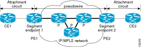
Figure 1 shows ATM transport over MPLS.
Figure 1 ATM Transport over MPLS
How to Configure OAM Segment Endpoint
See the following sections for tasks that use the oam-ac segment endpoint command to terminate the segment OAM cells on a VC:
•
•
Configuring OAM Segment Endpoint
This feature coexists with OAM emulation for Layer 2 VCs. If OAM emulation is already enabled, segment endpoint configuration is redundant. On the Cisco 12000 series router, F4/F5 distributed Operations, Administration and Maintenance (dOAM) is enabled by default.
SUMMARY STEPS
1.
2.
3.
4.
5.
6.
7.
8.
DETAILED STEPS
Verifying OAM Segment Endpoint
To verify whether the OAM Segment Endpoint feature is working correctly, use the following steps to monitor the segment cells (arriving on the Layer 2 transport VC) that are being terminated on ATM links in a network.
SUMMARY STEPS
1.
2.
DETAILED STEPS
Configuration Examples for OAM Segment Endpoint
This section contains the following configuration and verification examples:
•
OAM Segment Endpoint Configuration: Example
VC Layer 2 Transport
Router(config)# interface atm1/1Router(config-if)# pvc 0/100 l2transportRouter(cfg-if-atm-l2trans-pvc)# oam-ac segment endpointRouter(cfg-if-atm-l2trans-pvc)# endVC-Class Configuration
Router(config)# vc-class atm testRouter(config-vc-class)# oam-ac segment endpointRouter(config-vc-class)# endThe following is sample output for the show running-config interface command:
Router# show running-config interface atm1/1Building configuration...Current configuration : 177 bytes!interface ATM1/1no ip addressno ip directed-broadcastatm pvp 40 l2transportoam-ac segment endpointno atm enable-ilmi-trapno atm ilmi-keepalivepvc 0/100 l2transportoam-ac segment endpointendRouter# show running-configBuilding configuration...Current configuration : 4251 bytes!vc-class atm testoam-ac segment endpointoam-pvc manage!Verification Examples
The following is sample output from the show atm pvc command. It provides the segment OAM cell configuration and status information.
Router# show atm pvc 12/122VC 12/122 doesn't exist on interface ATM1/0 - cannot displayVC 12/122 doesn't exist on interface ATM1/1 - cannot displayATM1/2.3: VCD: 7, VPI: 12, VCI: 122UBR, PeakRate: N/A (UBR VC)AAL5 L2transport, etype:0xF, Flags: 0x10000C2E, VCmode: 0x0OAM Cell Emulation: not configuredOAM Segment Endpoint: enabled ============> oam-ac segment endpoint enabledInterworking Method: Not ConfiguredRemote Circuit Status = No Alarm, Alarm Type = NoneInPkts: 0, OutPkts: 0, InBytes: 0, OutBytes: 0InPRoc: 0, OutPRoc: 0InFast: 0, OutFast: 0, InAS: 0, OutAS: 0Out CLP=1 Pkts: 0OAM cells received: 0F5 InEndloop: 0, F5 InSegloop: 0,F5 InEndcc: 0, F5 InSegcc: 0, F5 InAIS: 0, F5 InRDI: 0OAM cells sent: 0F5 OutEndloop: 0, F5 OutSegloop: 0,F5 OutEndcc: 0, F5 OutSegcc: 0, F5 OutAIS: 0, F5 OutRDI: 0OAM cell drops: 0Status: UPRouter# show atm pvc 40/3ATM1/1: VCD: 48, VPI: 40, VCI: 3UBR, PeakRate: N/A (UBR VC)AAL5-MUX, etype:0x0, Flags: 0xD2C, VCmode: 0x0OAM frequency: 0 second(s), OAM retry frequency: 0 second(s) OAM up retry count: 0, OAM down retry count: 0 OAM Segment Endpoint: enabled OAM END CC Activate retry count: 0, OAM END CC Deactivate retry count: 0 OAM END CC retry frequency: 0 second(s), OAM SEGMENT CC Activate retry count: 0, OAM SEGMENT CC Deactivate retrycount: 0OAM SEGMENT CC retry frequency: 0 second(s),OAM Loopback status: OAM DisabledOAM VC state: Not ManagedILMI VC state: Not ManagedOAM END CC status: OAM CC ReadyOAM END CC VC state: Not ManagedOAM SEGMENT CC status: OAM CC ReadyOAM SEGMENT CC VC state: Not ManagedInARP DISABLEDInPkts: 0, OutPkts: 0, InBytes: 0, OutBytes: 0InPRoc: 0, OutPRoc: 0, Broadcasts: 0InFast: 0, OutFast: 0, InAS: 0, OutAS: 0Out CLP=1 Pkts: 0OAM cells received: 0F4 InEndloop: 0, F4 InSegloop: 0, F4 InAIS: 0, F4 InRDI: 0OAM cells sent: 0F4 OutEndloop: 0, F4 OutSegloop: 0, F4 OutAIS: 0, F4 OutRDI: 0 OAM cell drops: 0Status: UPAdditional References
The following sections provide references related to the OAM Segment Endpoint feature.
Related Documents
Cisco IOS commands
ATM Commands
Any Transport over MPLS
Detecting failures when using OAM cells and PVC management
Troubleshooting PVC Failures When Using OAM Cells and PVC Management
Layer 2 Tunnel Protocol Version 3
WAN configuration
Standards
IETF Specification
Encapsulation Methods for Transport of Layer 2 Frames over MPLS
IETF Specification
Layer Two Tunneling Protocol (Version 3)
IETF Specification
Transport of Layer 2 Frames over MPLS
ITU-T Specification I.610 (ITU-T specification for B-ISDN operation and maintenance principles and functions)
I.610 Series I: B-ISDN Operation and Maintenance Principles and Functions
1 Not all supported standards are listed.
MIBs
RFCs
Technical Assistance
Feature Information for OAM Segment Endpoint
Table 1 lists the features in this module and provides links to specific configuration information.
Not all commands may be available in your Cisco IOS software release. For release information about a specific command, see the command reference documentation.
Use Cisco Feature Navigator to find information about platform support and software image support. Cisco Feature Navigator enables you to determine which Cisco IOS and Catalyst OS software images support a specific software release, feature set, or platform. To access Cisco Feature Navigator, go to http://www.cisco.com/go/cfn. An account on Cisco.com is not required.

Note
Table 1 Feature Information for OAM Segment Endpoint
OAM Segment Endpoint
12.0(30)S
12.2(33)SREThe OAM Segment Endpoint feature terminates segment Operation, Administration and Maintenance (OAM) cells arriving on the Layer 2 transport virtual circuit (VC). The OAM Segment Endpoint feature helps in checking the segment connectivity. This feature can be used with Any Transport over MPLS (AToM) and Layer 2 Tunnel Protocol Version 3 (L2TPv3).
The following sections provide information about this feature:
•
The following commands were introduced or modified: oam-ac segment endpoint, show atm pvc.
Glossary
customer edge (CE) router—A router that belongs to a customer network, which connects to a provider edge (PE) router to utilize Multiprotocol Label Switching (MPLS) Virtual Private Network (VPN) network services.
provider edge (PE) router—Entry point into the service provider network. The PE router is typically deployed on the edge of the network and is administered by the service provider. The PE router is the redistribution point between Enhanced Interior Gateway Routing Protocol (EIGRP) and Border Gateway Protocol (BGP) in PE to CE networking.
pseudowire (PW)—A mechanism that carries the elements of an emulated service from one provider edge (PE) to one or more PEs over a packet-switched network (PSN).
VPN—virtual private network. Allows IP traffic to travel securely over public TCP/IP networks and the Internet by encapsulating and encrypting all IP packets. VPN uses a tunnel to encrypt all information at the IP level.
Note
Cisco and the Cisco Logo are trademarks of Cisco Systems, Inc. and/or its affiliates in the U.S. and other countries. A listing of Cisco's trademarks can be found at www.cisco.com/go/trademarks. Third party trademarks mentioned are the property of their respective owners. The use of the word partner does not imply a partnership relationship between Cisco and any other company. (1005R)
Any Internet Protocol (IP) addresses and phone numbers used in this document are not intended to be actual addresses and phone numbers. Any examples, command display output, network topology diagrams, and other figures included in the document are shown for illustrative purposes only. Any use of actual IP addresses or phone numbers in illustrative content is unintentional and coincidental.
© 2004-2009 Cisco Systems, Inc. All rights reserved.
 Feedback
Contact Cisco
- Open a Support Case

- (Requires a Cisco Service Contract)
This Document Applies to These Products
- Collaboration Endpoints - Retired Products
- Conferencing - Retired Products
- Contact Center - Retired Products
- Optical Networking - Retired Products
- Routers - Retired Products
- Security - Retired Products
- Servers - Unified Computing (UCS) Retired Products
- Storage Networking Retired Products
- Switches - Retired Products
- Video - Retired Products
- Wireless - Retired Products