Validated Profile: Financial (SD-Access and SD-WAN) Vertical
Available Languages
Bias-Free Language
The documentation set for this product strives to use bias-free language. For the purposes of this documentation set, bias-free is defined as language that does not imply discrimination based on age, disability, gender, racial identity, ethnic identity, sexual orientation, socioeconomic status, and intersectionality. Exceptions may be present in the documentation due to language that is hardcoded in the user interfaces of the product software, language used based on RFP documentation, or language that is used by a referenced third-party product. Learn more about how Cisco is using Inclusive Language.
- US/Canada 800-553-2447
- Worldwide Support Phone Numbers
- All Tools
 Feedback
 Feedback
Document purpose and use
The purpose of this document is to outline a typical finance deployment profile that Cisco recommends. It provides guidelines for a typical fabric deployment that uses Cisco Catalyst Center and serves as a validation document you can refer to during the process. Deployment engineers can use this document's theoretical sections in conjunction with its practical sections to help understand the service requirements to make the best decisions for their network during deployment and configuration.
Target audience
The target audience for this finance profile is the technical staff that is responsible for engineering and operating the network, as well as the implementation teams.
Solution overview
Financial organizations run thousands of branches throughout the world, ranging from small ATMs to large corporate offices spanning across multiple regions. While each site has its own specific requirements, the financial vertical requires standardized and secure network connectivity, simplified network operations and maintenance, highly failure-resilient systems, and a consistent policy implementation across the entire organization. The design and deployment considerations help achieve end-to-end segmentation and a consistent policy for the enterprise and branch locations of financial deployments.
This Cisco Validated Profile (CVP) document provides guidelines and focuses on the challenges, solution, deployment options, operational management, and migration for a financial profile network deployment. Validated end-to-end use cases, scaling, and hardware and software recommendations are provided so that you can make the best decisions for your organization during the deployment of your network. This document provides pointers to the associated design and deployment guides for enterprise networks, which provide guidance about how to deploy the most common implementations of a Cisco Catalyst Software-Defined Wide Area Network (SD-WAN) using Cisco Software-Defined Access (SD-Access) to achieve an end-to-end secured network for financial organizations.
Scope
This document serves as a valuable reference for understanding the available solutions. Included are common use cases, challenges, and explanations about how Catalyst SD-WAN and SD-Access solve the requirements for financial network deployments. Step-by-step instructions for configurations are not provided.
Traditional networks versus SD-Access and Catalyst SD-WAN
The following sections discuss the challenges of traditional network architecture and how Cisco SD-Access and Catalyst SD-WAN can address them.
Challenges in traditional networks
Organizations deploying traditional financial network architectures face mounting challenges as the number of users, devices, and types of devices continue to grow. Identifying, grouping, and analyzing the traffic of all these users and devices is a significant concern for organizations that want to ensure that they do not impact their corporate infrastructure should a device or network device become compromised. In traditional networks, the requirement for many virtual LANs (VLANs) and manual Access Control Lists (ACLs) across multiple and often disparate devices becomes a recipe for manual misconfiguration disasters. As the business expands over time, more devices and locations are added, increasing complexity and the possibility for errors. New and more complex security rules must be manually updated across the enterprise.
When the organization adds a new branch to the enterprise, the network operations team may require ACLs updates in both the headquarters and branch locations. If an error is made during the update, the security policy will become inconsistent and could result in a security breach. Network administrators must spend significant time planning and configuring network changes to ensure that every device is securely onboarded onto the network using the correct network segment. The traditional ways of building a network do not cater to the requirements of an evolving network and ever-growing security concerns.
Why SD-Access
SD-Access is built on an intent-based networking (IBN) foundation that encompasses visibility, automation, security, and simplification. Using Catalyst Center automation and orchestration, network administrators can implement changes across the entire enterprise environment through an intuitive interface. Using that same controller, they can build enterprise-wide fabric architectures, classify endpoints for security grouping, create and distribute security policies, and monitor network performance and availability.
SD-Access secures the network at the macrosegmentation and microsegmentation levels using Virtual Routing and Forwarding (VRF) tables and security group tags (SGTs). This is called multitier segmentation, which is not optimal in traditional networks. The security boundary is pushed to the very edge of the network infrastructure for both wired and wireless clients.
The security contexts associated with a user or device are dynamically assigned when they authenticate their network connection. SD-Access is superior to traditional network deployments for these reasons:
● Orchestration and automation complexity reduction and operational consistency
● Multitier segmentation that includes group-based policies
● Dynamic policy mobility for wired and wireless clients
Why Catalyst SD-WAN
The Catalyst SD-WAN solution is an enterprise-grade WAN architecture overlay that enables digital and cloud transformation for enterprises. It fully integrates routing, security, centralized policy enforcement, and orchestration into large-scale networks. It is multitenant, cloud-delivered, highly automated, secure, scalable, and application-aware with rich analytics. The Catalyst SD-WAN technology addresses the problems and challenges of common WAN deployments.
Benefits include:
● Centralized network and policy management, as well as operational simplicity, resulting in reduced change control and deployment times.
● Independent transport overlay that extends to the data center, branch, and cloud. A mix of Multiprotocol Label Switching (MPLS) and low-cost broadband or any combination of transports in an active/active method optimizes capacity and reduces bandwidth costs.
● Flexible deployment because the separation of the control plane and data plane allows the control components to be deployed on premises or in the cloud. The WAN edge router deployment can be physical or virtual and can be deployed anywhere in the network.
● Robust and comprehensive security that includes strong encryption of data, end-to-end network segmentation, router and control component certificate identity with a zero-trust security model, control plane protection, application firewall, and insertion of Cisco Umbrella, firewalls, and other network services.
● Seamless connectivity to the public cloud, and movement of the WAN edge to the branch.
● Visible and recognizable applications with real-time service-level agreement (SLA) enforcement and application-aware policies.
● Dynamic optimization of SaaS applications, resulting in improved application performance for users.
● Rich analytics with visibility into applications and infrastructure that enables rapid troubleshooting and assists in forecasting and analysis for effective resource planning.
The Catalyst SD-WAN solution offers the following use-case categories:
● Secure automated WAN: Secures connectivity between remote offices, data centers, and public or private cloud over a transport-independent network.
● Application performance optimization: Improves the application experience for users at remote offices.
● Secure direct internet access: Offloads locally the internet traffic at the remote office.
● Multicloud connectivity: Connects remote offices with cloud (SaaS and IaaS) applications over an optimal path and through regional colocation or exchange points where security services can be applied.
For more information, see the Catalyst SD-WAN Data Sheet.
Catalyst SD-WAN components
The Catalyst SD-WAN solution uses separate planes for orchestration, management, control, and data. The orchestration plane assists in the automatic onboarding of routers into the Catalyst SD-WAN overlay. The management plane is responsible for central configuration and monitoring. The control plane builds and maintains the network topology and makes decisions on where traffic flows. The data plane is responsible for forwarding packets based on decisions from the control plane.
The primary components for the Catalyst SD-WAN solution consist of the SD-WAN Manager network management system (management plane), the SD-WAN Controller (control plane), the SD-WAN Validator (orchestration plane), and the WAN edge router (data plane).
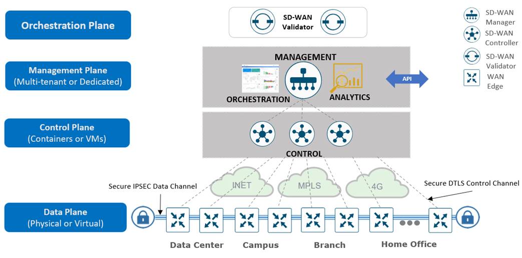
● SD-WAN Manager
A centralized, software-based network management system with a graphical user interface (GUI) used to conveniently monitor, configure, and maintain all Catalyst SD-WAN devices and their connected links in the underlay and overlay networks. It provides a single visual dashboard for day zero, day one, and day two operations. For a complete summary of recommended computing resources for the Catalyst SD‑WAN control components for software version 20.15, see the Control Components Compatibility Matrix.
● SD-WAN Controller
A software-based component responsible for the centralized control plane of the SD-WAN network. It maintains a secure connection to each WAN edge router and distributes routes and policy information via the Overlay Management Protocol (OMP), acting as a route reflector. It also orchestrates the secure data plane connectivity between the WAN edge routers by reflecting crypto key information originating from WAN edge routers, which allows for a scalable architecture without an Internet Key Exchange (IKE) protocol.
● SD-WAN Validator
A software-based component that does the initial authentication of WAN edge devices and orchestrates SD-WAN Controller, Manager, and WAN edge connectivity. It also has a key role in enabling communication between devices located behind Network Address Translation (NAT).
● WAN edge router
A device, available as either a hardware appliance or software-based router, located at a physical site or in the cloud, that provides secure data plane connectivity between the sites over one or more WAN transports. It is responsible for traffic forwarding, security, encryption, Quality of Service (QoS), routing protocols such as Border Gateway Protocol (BGP) and Open Shortest Path First (OSPF), and more.
SD-Access components
Catalyst Center
Catalyst Center is a powerful management system that simplifies, connects, secures, and automates network operations. Catalyst Center simplifies management of the Catalyst network infrastructure and ensures a consistent user experience across wired and wireless networks. It delivers enterprise-scale, secure, seamless, and reliable connectivity among users, applications, and things.
Benefits:
● Simplifies operations and reduces operational costs by leveraging AI and automating network operations.
● Improves user experiences with deep insights into business-critical applications and client health.
● Accelerates digital agility through business process automation using Cisco and a third-party ecosystem.
● Secures the digital enterprise with intuitive security policy management, AI-enabled enforcement, and automated compliance checks.
● Drives sustainability by enabling smart buildings and optimizing a Power over Ethernet (PoE) infrastructure.
● Supports both physical appliances and virtual appliances.
For more details, see the Catalyst Center Data Sheet.
For the Catalyst Center installation guides, see the Install and Upgrade Guides.
Cisco Identity Services Engine
Identity Services Engine (ISE) is a secure network access platform enabling increased management awareness, control, and consistency for users and devices accessing an organization's network. ISE is an integral and mandatory part of SD-Access for implementing network access control policy. ISE performs policy implementation, enabling dynamic mapping of users and devices to scalable groups, and simplifying end-to-end security policy enforcement. Catalyst Center is used as the dashboard to manage and create SGTs and define their policies. Group and policy services are driven by ISE and orchestrated by Catalyst Center's policy authoring workflows. Policy management with identity services is enabled in an SD-Access network using ISE integrated with Catalyst Center for dynamic mapping of users and devices to scalable groups. This simplifies end-to-end security policy management and enforcement at a greater scale than traditional network policy implementations relying on IP access lists.
ISE supports standalone and distributed deployment models. Multiple, distributed nodes can be deployed together to provide failover resiliency and scale. The range of deployment options allows support for hundreds of thousands of endpoint devices. Minimally, a basic two-node ISE deployment is recommended for SD-Access single-site deployments with each ISE node running all services (personas) for redundancy. SD-Access deployments can be running without ISE integration for policy management.
For deployment models, see the Cisco Identity Services Engine Administrator Guide.
For more details, see the ISE Performance and Scalability Guide.
Cisco Catalyst 9000 series switches
Catalyst 9000 series switches offer flexible and highly scalable design options. Switches supported in different fabric roles offer secure, fast, and reliable connectivity to users and endpoints within the network. For more details, see the Catalyst 9000 switching family data sheets.
Cisco Catalyst Wireless LAN Controller and Access Point
Cisco Catalyst 9800 Series Wireless LAN Controllers and access points (AP) provide seamless network management and deployment in both on-premises and cloud for wireless clients. For the complete data sheet of Catalyst 9800 Series and Catalyst 9100 Series devices, see:
● Cisco Access Point and Wireless Controller Selector
SD-Access fabric
SD-Access is the evolution from traditional campus LAN designs to networks that explicitly implement an organization's intent. Fabric technology, an integral part of SD-Access, provides wired and wireless campus networks with programmable overlays and easy-to-deploy network virtualization, allowing a physical network to host one or more logical networks to meet the design intent.
In addition to network virtualization, fabric technology in the campus network enhances control of communications, providing software-defined segmentation and policy enforcement based on user identity and group membership. Software-defined segmentation is seamlessly integrated using Cisco TrustSec, providing microsegmentation for groups within a virtual network (VN) using SGTs. Using Catalyst Center to automate the creation of VNs with integrated security and segmentation reduces operational expenses and reduces risk. Network performance, network insights, and telemetry are provided through the Assurance and Analytics capabilities. SD-Access provides policy mobility for both wired and wireless clients.
Fabric architecture overview
The following sections provide an overview of the SD-Access architecture and solution components.
Solution components
The SD-Access solution is provided through a combination of Catalyst Center, ISE, and wired and wireless device platforms that have fabric functionality leveraging the Locator/ID Separation Protocol (LISP) for fabric overlay. As described later in the fabric roles section, the wired and wireless device platforms are used to create the elements of a fabric site. Catalyst Center software, including the SD-Access application package, runs on a Catalyst Center hardware appliance.
Operational planes
The network planes of operation include the following:
● Control plane: Messaging and communication protocol between infrastructure devices in the fabric.
● Data plane: Encapsulation method used for the data packets.
● Policy plane: Used for security and segmentation.
● Management plane: Orchestration, assurance, visibility, and management.
In SD-Access the control plane is based on LISP, the data plane is based on Virtual Extensible LAN (VXLAN), the policy plane is based on Cisco TrustSec, and the management plane is enabled and powered by Catalyst Center.
Network architecture
The SD-Access architecture is supported by fabric technology implemented for the campus, enabling the use of VNs (overlay networks) running on a physical network (underlay network) creating alternative topologies to connect devices. In SD-Access, the user-defined overlay networks are provisioned as VRF instances that provide separation of routing tables.
Fabric roles
A fabric role is an SD-Access software construct running on physical hardware.
● Control plane node
The SD-Access fabric control plane node is based on the LISP Map-Server and Map-Resolver functionality combined on the same node. The control plane node’s database tracks all endpoints in the fabric site and associates the endpoints to fabric nodes, decoupling the endpoint IP address or MAC address from the location (closest router) in the network.
● Edge node
The SD-Access fabric edge nodes are the equivalent of an access layer switch in a traditional campus LAN design. The edge node provides endpoint registration locally and updates the control plane node. The edge node provides anycast Layer 3 gateway for the hosts to connect to the fabric network and acts as an authentication relay agent for the hosts.
● Intermediate node
Intermediate nodes are part of the Layer 3 network used for interconnections among the devices operating in a fabric role such as the interconnections between border nodes and edge nodes. These nodes provide IP reachability, physical connectivity, and support the added Maximum Transmission Unit (MTU) requirement to accommodate the larger-sized IP packets encapsulated with fabric VXLAN information.
● Border node
Fabric border nodes serve as the gateway between the SD-Access fabric site and the networks external to the fabric. The border node can extend network virtualization from inside the fabric to outside the fabric by using VRF-lite and VRF-aware routing protocols to preserve the segmentation. This may be a single switch, a switch with hardware stacking, or a StackWise Virtual deployment.
● Fabric in a box
Fabric in a box is an SD-Access construct where the border node, control plane node, and edge node are running on the same fabric node. This may be a single switch, a switch with hardware stacking, or a StackWise Virtual deployment. For more details, see the StackWise Virtual White Paper.
● Extended node
SD-Access Extended nodes offer the ability to extend the enterprise network by providing connectivity to noncarpeted spaces of an enterprise, commonly called the Extended Enterprise. Extended nodes offer a Layer 2 port extension to a fabric edge node while providing segmentation and group-based polices to the endpoints connected to these switches. For more details, see the Extended Node Design.
● Fabric Wireless LAN Controllers and APs
Fabric wireless controllers and nonfabric wireless controllers provide AP image and configuration management, client session management, and mobility services. Fabric wireless controllers provide added services for fabric integration such as registering MAC addresses of wireless clients into the host tracking database of the fabric control plane nodes. The fabric-mode APs are Cisco Wi-Fi 6 (802.11ax) and 802.11ac Wave 2 APs associated with the fabric wireless controller that have been configured with one or more fabric-enabled SSIDs. Fabric-mode APs continue to support the same wireless media services that traditional APs support, such as applying Application Visibility and Control (AVC), QoS, and other wireless policies. For more details, see the SD-Access Wireless Design and Deployment Guide.
● SD-Access embedded wireless
Wireless controller functionality without a hardware wireless controller in distributed branches and small campuses can be achieved with the Catalyst 9800 Embedded Wireless Controller available for Catalyst 9000 Series switches as a software package. The Catalyst 9800 Embedded Wireless Controller for Catalyst 9000 Series switches supports SD-Access deployments with the following Catalyst 9000 Series switches topologies:
◦ Functioning as a colocated border and a control plane.
◦ Functioning as an edge node when the border and control plane node are on a routing platform.
◦ Functioning as a fabric in a box.
● Transit and peer network
SD-Access is a construct that defines how Catalyst Center automates the border node configuration for the connections between fabric sites or between a fabric site and the external world. This connectivity may be MAN, WAN, or internet. There are two distinct types of transit networks available in an SD-Access fabric, SD-Access transit and IP transit to connect Distributed Campuses and an external network.
● Transit control plane nodes
Transit control plane nodes are a fabric role construct supported in SD-Access for a Distributed Campus. It works the same way as a site-local control plane node, except it services the entire fabric. Transit control plane nodes are only required when using SD-Access transits. For more information, see SD-Access and the Distributed Campus Deployment Guide.
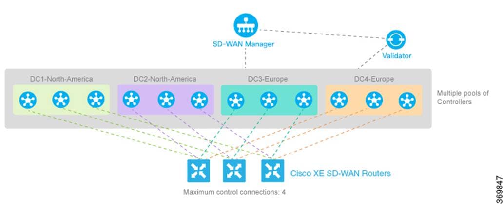
Catalyst SD-WAN solution constructs
The following diagram demonstrates several aspects of the Catalyst SD-WAN solution. This sample topology depicts two WAN edge sites, each directly connected to a private MPLS transport and a public internet transport. The cloud-based SD-WAN Controllers, the SD-WAN Validator, along with the SD-WAN Manager are accessible directly through internet transport. In addition, the topology includes cloud access to SaaS and IaaS applications.
The WAN edge routers form a permanent DTLS or TLS control connection to the SD-WAN Controllers and connect to both SD-WAN Controllers over each transport. The routers also form a permanent DTLS or TLS control connection to the SD-WAN Manager, but over just one of the transports. The WAN edge routers securely communicate with other WAN edge routers using IPsec tunnels over each transport. The Bidirectional Forwarding Detection (BFD) protocol is enabled by default and runs over each of these tunnels, detecting loss, latency, jitter, and path failures.
● Site ID
A unique identifier of a site in the Catalyst SD-WAN overlay network with a numeric value 1 through 4294967295. It identifies the source location of an advertised prefix. This ID must be configured on every WAN edge device, including the control components, and must be the same for all WAN edge devices that reside at the same site. A site could be a data center, a branch office, a campus, or something similar. By default, IPsec tunnels are not formed between WAN edge routers within the same site that share the same site-id.
● System IP
Persistent, system-level IPv4 address that uniquely identifies the device independently of any interface addresses. It acts much like a router ID, so it doesn't require advertisement or knowledge by the underlay. It is assigned to the system interface that resides in VPN 0 and is never advertised. A best practice, however, is to assign this system IP address to a loopback interface and advertise it in any service VPN. It can then be used as a source IP address for SNMP and logging, making it easier to correlate network events with SD-WAN Manager information.
● Organization name
Assigned to the entire Catalyst SD-WAN overlay, this field is case sensitive and must match the organization name configured on all the Catalyst SD-WAN devices in the overlay. It is used to define the Organization Unit (OU) field to match in the Certificate Authentication process when a Catalyst SD-WAN device is brought into the overlay network.
● Private and Public IP addresses
◦ Private IP address
On WAN edge routers, the private IP address is the IP address assigned to the interface of the Catalyst SD-WAN device. This is the pre-NAT address, and despite the name, can be a public address or a private address (RFC 1918).
◦ Public IP address
This is the post-NAT address detected by the SD-WAN Validator. This address can be either a public address (publicly routable) or a private address (RFC 1918).
In the absence of NAT, the private and public IP address of the Catalyst SD-WAN device is the same.
● TLOC
The Transport Locator (TLOC) is the attachment point where a WAN edge router connects to the WAN transport network. A TLOC is uniquely identified and represented by a three-tuple: System IP, link color, and Encapsulation GRE/IPSec.
● Color
Applies to WAN edge routers or SD-WAN Managers and Controllers and helps to identify an individual TLOC; different TLOCs are assigned different color labels. The example Catalyst SD-WAN topology uses a public color called “biz-internet” for the internet transport TLOC and a private color called “mpls” for the other transport TLOC.
● Overlay management protocol
The overlay management protocol (OMP) is the core routing protocol of Catalyst SD-WAN that has a structure like BGP and manages the Catalyst SD-WAN overlay network. The protocol runs between SD-WAN Controllers and between SD-WAN Controllers and WAN edge routers where control plane information, such as route prefixes, next-hop routes, crypto keys, and policy information, is exchanged over a secure DTLS or TLS connection. The SD-WAN Controller acts like a BGP route reflector; it receives routes from WAN edge routers, processes and applies any policy to them, and then advertises them to other WAN edge routers in the overlay network.
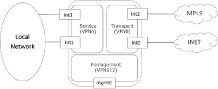
● Virtual private networks (VPNs)
In the Catalyst SD-WAN overlay, VPNs provide segmentation, much like VRFs. Each VPN is isolated from one another, and each VPN has its own forwarding table. An interface or subinterface is explicitly configured under a single VPN and cannot be part of more than one VPN. Labels are used in OMP route attributes and in the packet encapsulation, which identifies the VPN a packet belongs to. There are two main VPNs present by default in the WAN edge devices and control components, VPN 0 and VPN 512. VPN 0 is a transport VPN. It contains the interfaces that connect to the WAN transports. Secure DTLS/TLS connections to the control components are initiated from this VPN. VPN 512 is the management VPN. It carries the out-of-band management traffic to and from the Catalyst SD-WAN devices.
The following figure illustrates VPNs on a WAN edge router. The interfaces, Int0 and Int2, are part of the transport VPN; Int1 and Int3 are part of the service VPN that is attached to the local network at the site. The mgmt0 port is part of VPN 512.
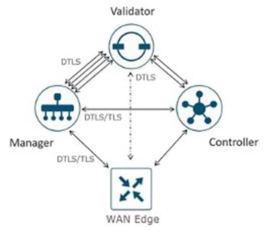
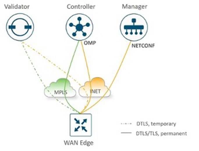
● Control Connections
The Catalyst SD-WAN Manager and Controllers initially contact and authenticate to the SD-WAN Validator, forming persistent DTLS connections, and then subsequently establish and maintain persistent DTLS/TLS connections with each other. WAN edge devices onboard in a similar manner but drop the transient SD-WAN Validator connection and maintain DTLS/TLS connections with the SD-WAN Manager and Controllers.
The following diagrams illustrate various control connections between controllers and WAN edge devices.
For details, see the Catalyst SD-WAN Design Guide.
Compatibility matrix
Catalyst Center provides coverage for Cisco enterprise switching, routing, and mobility products. For a complete list of Cisco products supported, see our compatibility matrix:
● Cisco Catalyst Center Compatibility Matrix
● Cisco SD-Access Compatibility Matrix
● Catalyst SD-WAN Compatibility Matrix
Financial profile deployment
This section offers design guidance for the financial space focusing on the requirements and how SD-Access and Catalyst SD-WAN are used in this vertical to have a simple, secure, and flexible network.
The topologies, use cases, and solutions focus on the themes and requirements of standard financial deployments.
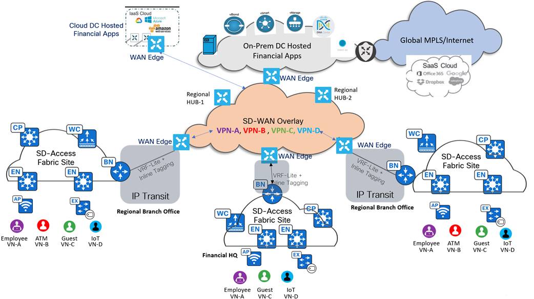
The following figure illustrates a large financial, multiregional campus and branch deployment:
Business outcomes and challenges
Financial networks are widespread, diverse, and complex with unique challenges. These networks must fulfill the requirement of elevated levels of security, resilience, and regulatory compliances.
The following are the most critical capabilities present in a financial organization network to achieve business outcomes.
Financials
Streamline expenses and boost earnings through deployment automation across thousands of sites while minimizing the requirement for onsite network operations whenever possible.
Large-scale multisite deployments
Financials are typically large multisite deployments that run thousands of sites across vast geographic regions. It is an enormous challenge to deploy and manage such large networks box-by-box or site-by-site with onsite network management teams. To maintain complex site deployments with minimal manual work, automation is critical.
Automation and monitoring
Given the global footprint of large financials, a solution is required so that any location can be brought up faster and managed remotely by a lean IT staff. The requirement is to have automation and assurance in the network to reduce the complexity and time spent on deployments and troubleshooting.
Security
To enhance security, mitigate risks, and ensure compliance with regulatory standards, financial networks must implement robust security protocols, conduct regular risk assessments, and adhere to industry-specific regulations and standards.
For financial customers, the choice between on-premises and cloud-based Catalyst SD-WAN security solutions depends on specific requirements and priorities. On-premises solutions offer control, compliance, and customization essential for handling sensitive financial data. In contrast, cloud-based solutions provide scalability, advanced security features, and cost efficiency, which can be crucial for rapidly evolving environments. A hybrid approach may often be the most advantageous, leveraging the strengths of both on-prem and cloud-based security to meet diverse operational requirements.
Cybersecurity threats are the biggest threat to a financial company's Chief Information Security Officer (CISO). The rapid transition to hybrid work and the evolution of digital business services to customers have massively increased attack surface vectors available to cyber criminals.
If not kept in check, these bad actors can take advantage of vulnerabilities and cause massive losses in both financial and reputational terms. The CISO group periodically reviews basic security fundamentals and security processes.
Isolation of guest users
Customers visiting financial branches bring different endpoints that could be compromised, so the traffic from guest devices must be isolated and inspected. In such scenarios, the next-generation network must support traffic inspection for wired and wireless guest traffic, which means the first-hop for all guest traffic must be a firewall in a demilitarized zone (DMZ).
Compliance regulations
Financial systems must protect extremely sensitive financial records and information of customers, and they are strictly bound by government regulations. For example, the payment card industry (PCI-DSS) standards include mandates such as data encryption in flight, security mandates for storing customer data, and tracking and monitoring network resources and cardholder data. Financial networks must provide complete and constant visibility for network management and monitoring.
Because different departments and guests all share the same network infrastructure, every group must be isolated from one another and restricted to only the resources they are allowed to access. At the same time, these diverse groups of users and devices require access to shared services.
User experience
For financial customers, application experience must be tailored to meet the distinct requirements of employees and guests. Employees benefit from optimized, secure, and compliant access to critical financial applications, ensuring efficient and uninterrupted workflow. In contrast, guests receive isolated, limited access that prioritizes security and basic functionality, ensuring that the core network remains protected. This differentiation ensures that financial institutions can maintain high standards of security and performance while accommodating various user requirements.
High sensitivity to QoS
In addition to worrying about security, compliance, and availability, a slow and QoS-disparate network can lead to poor customer satisfaction and monetary losses. When it comes to trading floors, which are overly sensitive to delays, low latency and consistent QoS are mandatory to fulfill the organizational requirements.
Operational
Maximize productivity and ease digital transformation initiatives while effectively managing reputation and enhancing brand value.
High availability
Due to the criticality of financial systems in our daily lives, 100% availability is the goal. A five-nines availability comes close to 100% availability and guarantees that the network will be up for 99.999% of the time (roughly 5 minutes and 16 seconds of outage a year). Automation, monitoring, load-balancing, and failover schemes can allow financial firms to meet or beat the goal of five-nines availability.
Centralized and consistent policy management
With exponential growth in the number of endpoints connecting to the network and the spanning of large financial organizations across the globe, there is a requirement to manage security policy in different geographical regions.
This leads to management complexity as the rules may be driven by the local laws. There is a crucial requirement to simplify the grouping of users and devices so that security policies can be managed intuitively.
Video streaming across branches and headquarters
As the trading business for financial organizations has grown rapidly, working with real-time information is a primary focus area.
Financial traders require access to real-time data to remain competitive in the marketplace. Banks want to display programs and strategies to visiting customers through IPTV-based ads and videos running continuously in all branches.
Acquisitions integration
To reap the full collaboration and benefits of acquiring an organization, the systems of the two merging organizations must be integrated to optimize redundant operations. The network is usually the first integration area, but this must be done securely so that the organization is not exposed to new vulnerabilities.
Solutions to financial challenges and business outcomes
The solutions discussed here help to achieve the business requirements identified for financial network deployments.
Financial
Automation and monitoring are essential components of modern IT infrastructure management. Automation can include tasks such as software deployment, configuration management, system provisioning, and workflow orchestration. By automating repetitive and time-consuming tasks, organizations can improve efficiency, reduce errors, and free human resources to focus on more strategic activities. Monitoring, however, involves continuously observing and analyzing the performance and health of IT systems, networks, applications, and services.
SD-WAN Manager is a key component of the Catalyst SD-WAN solution. It plays a crucial role in simplifying network operations by providing centralized management and control of the Catalyst SD-WAN infrastructure. The following are several ways in which SD-WAN Manager simplifies network operations:
● Centralized management
Offers a single dashboard view of the entire Catalyst SD-WAN network, making it easier for network administrators to configure, monitor, and manage network resources. Centralized management simplifies network administration by reducing the requirement for accessing and managing individual network devices.
● Automation and orchestration
SD-WAN Manager provides automation and orchestration capabilities that allow administrators to centrally define and enforce network policies. This eliminates the requirement for manual configuration on individual devices, which reduces the risk of human error and ensures consistent network policy enforcement across the network.
● Application visibility and control
SD-WAN Manager offers deep visibility into network traffic and application performance. It enables administrators to identify and prioritize critical applications, which ensures that they receive the necessary network resources. This simplifies network operations by improving application performance and user experience.
Zero-touch provisioning
SD-WAN Manager supports zero-touch provisioning, which eliminates the requirement for manually deploying new SD-WAN device configurations. This reduces deployment time and minimizes the requirement for onsite technical expertise. Integration with the Cisco Plug-and-Play (PnP) portal on the back end simplifies onboarding of edge locations.
LAN automation
Cisco LAN automation simplifies network operations, frees IT staff from time-consuming, repetitive network configuration tasks, and creates a standard, error-free underlay network. LAN automation accelerates building the underlay network without the traditional network planning and implementation process.
LAN automation provides the following key benefits:
● Zero-touch provisioning
Network devices are automatically detected, set up, and integrated into the network from their original factory settings without manual intervention.
● End-to-end topology
New network systems are automatically discovered, and their connections can be modeled and programmed. These systems can be automated with Layer 3 IP addressing and routing protocols to create dynamic end-to-end routing topologies.
● Resilience
LAN automation integrates system and network configuration parameters that optimize forwarding topologies and redundancy. Cisco LAN automation enables system-level redundancy and automates best practices to enable best-in-class resiliency during planned or unplanned network outages.
● Security
Recommended network access and infrastructure protection parameters are automated, which provides security from the initial deployment.
● Compliance
LAN automation helps eliminate human errors, misconfigurations, and inconsistent rules and settings that drain IT resources. During new system onboarding, LAN automation provides compliance across the network infrastructure by automating globally managed parameters from Catalyst Center.
For more details, see the SD-Access LAN Automation Deployment Guide.
Troubleshooting using Intelligent Capture
Financial customers often lack an onsite network support team in smaller branches, making troubleshooting difficult.
Catalyst Center Intelligent Capture capability provides support for a direct communication link between Catalyst Center and APs in SD-Access wireless environments. Catalyst Center can receive packet capture data, AP and client statistics, and spectrum data. With the direct communication link between Catalyst Center and APs, Intelligent Capture allows access to data from APs that are not available from wireless controllers.
PnP and Return Material Authorization (RMA)
Catalyst Center automates the deployment of Catalyst 9000 series switches at branches or campuses using built-in PnP functionality, which enables easy onboarding to the network for switches, routers, and wireless APs. An agent installed on the device will call-home to Catalyst Center and download the required software and device configuration from Catalyst Center.
Replacing older hardware in a large enterprise network is complex. It involves identifying the right replacement hardware with compatible software versions, ensuring accurate configuration, and avoiding errors during setup. This process requires careful planning and execution to maintain network stability and performance. Catalyst Center offers a complete workflow to seamlessly identify, replace, and configure hardware in the network. For more details, see Network Device Onboarding, the Onboard a cEdge Device with PnP Process and Cisco Plug and Play Support Guide for Cisco SD-WAN Products.
Software upgrade and image management
To automate the upgrade of a Catalyst 9000 Series switch at a branch or campus, use the Catalyst Center Software Image Management (SWIM) solution, which standardizes software images for your network devices. For more details, see Software Image Management.
Catalyst Center stores all the unique software images according to image type and version for the devices in your network. SWIM lets you view, import, and delete software images and push them to your network devices.
SD-WAN Manager allows you to centrally upgrade the software on Catalyst SD-WAN edge devices in the overlay network and reboot them with the new software. You can simultaneously do this for a single device or for multiple devices. The software upgrade can also be scheduled later. SD-WAN Manager provides workflows to run upgrades on the SD-WAN Controller and SD-WAN Validator instances. For more details, see the SD-WAN Monitor and Maintain Configuration Guide.
Security
To solve security challenges, implement comprehensive measures such as robust encryption protocols, regular security audits, and proactive threat monitoring to safeguard against potential cyber threats and data breaches. This solution leverages the built-in security features as well as the integration of ISE and Catalyst Center to provide highly secure and segmented systems.
Catalyst Center scales the network and still restricts access to critical applications in the fabric while improving situational awareness on the network. ISE gathers real-time contextual information from networks, users, and devices for Catalyst Assurance. This integration simplifies the advanced security requirements of the financial institution that strives to prevent fraud and protect confidential data. The integration facilitates the provisioning of network access, accelerates security operations, and consistently enforces policies anywhere in the network.
In the financial sector, security requirements are met through group-based policy (GBP) and identity-based access control features like IEEE 802.1X and MAC Authentication Bypass. These features, along with site-level MACsec encryption and Fully Qualified Domain Names-based (FQDN-based) certificates, ensure secure access and data protection.
Financial institutions have strict security and compliance requirements. Catalyst SD-WAN addresses these with features like robust segmentation, strong encryption, zero-trust security, advanced threat protection, continuous monitoring, compliance, audit capabilities, and integration with existing security systems. By implementing these security measures with Catalyst SD-WAN, financial institutions can ensure a secure, resilient, and compliant network environment. This protects sensitive financial data and maintains the trust of customers and stakeholders, ultimately supporting the overall institution business objectives.
The Catalyst SD-WAN solution offers security measures at all levels, including:
● Control plane
Catalyst SD-WAN fabric incorporates a zero-trust security model within its control plane. This ensures that all elements of the fabric are authenticated and authorized before network admittance. This model is built on digital certificates to establish the identity of each fabric element used in authentication. The certificates are used to establish secure TLS or DTLS control channels between the controllers and between the WAN edge routers and the various controllers. TLS and DTLS use Advanced Encryption Standard (AES-256) encryption algorithm to encrypt all control traffic sent over the control connections. AES-256-GCM is also used for integrity, to ensure traffic has not been tampered with. An authorization list is required for WAN edge devices to be admitted into the network.
● Data plane
For the data plane, authentication is enforced by using both a key exchange model and an enhanced version of the Encapsulating Security Payload (ESP) protocol. The enhanced version of ESP protects the data packet payload through encryption using the AES-GCM-256 cipher.
● Management plane
The management plane uses role-based access control (RBAC) and ACLs to manage which users and devices can access the SD-WAN Manager by specifying allowed source IP addresses.
Catalyst SD-WAN Manager provides a comprehensive security framework tailored to the requirements of financial institutions. With strong encryption, multifactor authentication, RBAC, and integration with external IDP providers, SD-WAN Manager ensures that the management plane remains secure and resilient. These features help financial institutions protect sensitive data, comply with regulatory requirements, and maintain high levels of performance and reliability. By leveraging SD-WAN Manager, financial customers can confidently manage their networks, knowing they have a robust security foundation in place.
Endpoint security with zero-trust solution
Networks require protection against external and internal threats. The SD-Access zero-trust security solution provides secure access to users and devices from all locations across the network. The SD-Access zero-trust security solution provides the flexibility to adopt a path to a zero-trust workplace based on your network settings and services. You can configure how users connect to the network using dynamic rules and automated segmentation.
The SD-Access zero-trust security solution provides the capability to automate network access policies using the following features:
● Endpoint visibility: Identify and group endpoints. Map their interactions through traffic flow analysis and define access policies.
● Trust monitoring: Continuously monitor the endpoint behavior, scan for vulnerabilities, verify trustworthiness for continued access, and isolate rogue or compromised endpoints.
● Network segmentation: Enforce group-based access policies and secure the network through multilevel segmentation.
SD-Access can force network devices such as APs and switches to be securely onboarded using IEEE 802.1x mechanisms. This protects the network from the attachment of unauthorized devices by maintaining closed authentication on all edge node APs. Extended nodes onboarded securely using closed authentication are called supplicant-based extended nodes (SBEN).
SBEN are provisioned as policy extended nodes by Catalyst Center to have a supplicant with EAP-TLS authentication on their uplink to the edge node. The EAP-TLS certificate is provisioned by Catalyst Center using Catalyst Center Certificate Authority (CA). After successful onboarding, access to the port is only based on authentication status. If the device or port fails, the authentication session is cleared, and traffic is rejected. When the port comes back, it goes through dot1x authentication to regain access to the SD‑Access network. Secure AP onboarding is done by authorizing the AP on a closed authentication port by allowing limited access to DHCP with DNS and Catalyst Center for the PnP workflow. The PnP workflow on Catalyst Center enables a dot1x supplicant on the AP, and the AP uses this supplicant to authenticate with ISE.
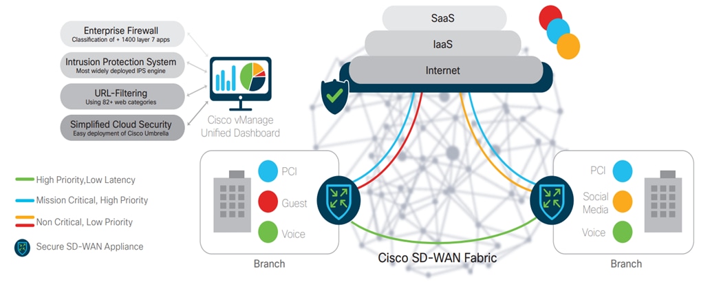
Branch users and devices
Threat protection for branch users and devices involves features that safeguard against threats like DDOS, unauthorized access, viruses, malware, and ransomware. This includes embedded security features on SD-WAN branch routers such as zone-based firewalls, intrusion prevention and detection systems (IPS and IDS), URL filtering, advanced malware protection (AMP), SSL with TLS proxy, and DNS with web-layer security and Cisco Umbrella integration.
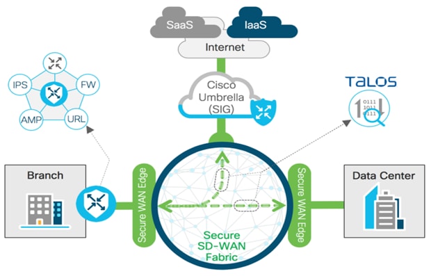
For details, see Catalyst SD-WAN security.
Cisco AI Endpoint Analytics
Cisco AI Endpoint Analytics, our next-generation endpoint visibility solution, gathers deeper context from your network and IT ecosystem to make all endpoints visible and searchable. It detects and reduces the number of unknown endpoints in your enterprise using the following techniques:
● Deep packet inspection (DPI) gathers deeper endpoint context by scanning and understanding applications and communications protocols of IT, building automation and healthcare endpoints.
● Machine learning (ML) intuitively groups endpoints with common attributes and helps IT administrators label them. These unique labels are then anonymously shared with other organizations as suggestions, where similar groups of unknown endpoints may be seen. This helps reduce the unknown endpoints and group them based on newer labels.
● Integrations with Cisco and third-party products provide added network and non-network context that is used to profile endpoints.
AI Endpoint Analytics reduces or ends the first hurdle that many customers face when implementing security policies, like overcoming a lack of visibility of endpoints, with high fidelity. It is available in Catalyst Center Release 2.1.2.x and later as a new application. Customers with subscription-level Catalyst Advantage and higher have access to AI Endpoint Analytics. The following short technology primers will look at AI Endpoint Analytics and how Cisco customers stand to benefit from it:
● Cisco SD-Access AI Endpoint Analytics
● AI Endpoint Analytics Catalyst Center Guide
Cisco Stealthwatch Security Analytics service
The Cisco Stealthwatch Security Analytics service on Catalyst Center, in conjunction with Stealthwatch, provides real-time monitoring of all network traffic. The Stealthwatch Security Analytics service on Catalyst Center automates network setup to send data to Stealthwatch, enhancing visibility and malware detection.
For more details, see the Stealthwatch Security Analytics Service on Cisco Catalyst Center User Guide.
End-to-end encryption
Financial customers require data traveling across their network to be encrypted to ensure privacy, data confidentiality, and compliance with regulatory requirements. Financial institutions typically require encryption at Layer 2 within their corporate networks and at Layer 3 across the WAN. Within the fabric site, encryption at the MAC layer is accomplished using Media Access Control Security (MACsec).
To provide encryption on these links, use MACsec. MACsec is the lEEE 802.1AE standard that enables devices on Ethernet networks to provide confidentiality, integrity, and authenticity for data in transit. Switch-to-host and switch-to-switch MACsec can be enabled in the SD-Access network on compatible switches via templates in Catalyst Center. Encryption at the WAN is handled by IPsec tunnels between each WAN edge router.
Network segmentation
Network segmentation is essential for protecting critical business assets. Catalyst Center provides a simplified approach, called macrosegmentation, to protect data between VNs. Catalyst Center also provides the framework for deploying microsegmentation using group-based access control for endpoints within VNs.
The concept of network segmentation is not new, but it has evolved significantly. Initially, network segmentation was defined as the process of breaking up one flat network or broadcast domain into smaller segments with VLANs.
As requirements were established to extend network segments across organizations, regardless of location, the concept of VNs or VRF instances was used to implement Layer 3 isolation between network segments.
Isolation is inherent, as each VRF maintains its own routing and forwarding, thereby creating a VN. Isolation is achieved because routes contained in one VRF are not present in another, thereby limiting communications between them. With GBP, segmentation is no longer performed based on VLANs or VRFs with IP addressing and routing. Instead, GBP relies on the use of role‑based or group-based membership, regardless of IP addressing, to create policies that allow segmentation of the network.
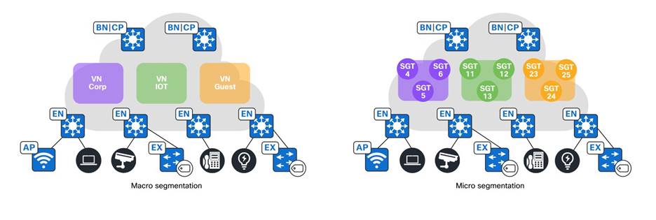
Macrosegmentation
In financial networks, a preferred segmentation method is to separate network endpoints like employees, ATMs, monitoring devices, and guests into different VRFs. SD-Access allows for the separation of network endpoints into different VRFs for better security and management, and this can be set up using Catalyst Center.
For example, up to five VNs may be deployed within branch and data center sites. Strict separation of traffic between VNs is both required and maintained by the financial network. These VNs consist of the following:
● Employee VN: Used for internal business applications.
● ATM VN: Used for ATMs and other devices accessing internal financial applications.
● Monitoring VN: Used for logging information (syslog and/or SNMP traps) and in-band management.
● Guest VN: Used primarily for guest Wi-Fi access to the customer-facing web applications reachable via the internet.
● INFRA VN: Used only for APs and extended nodes mapped to the global routing table. The wireless controller sits outside the fabric. The border node is responsible for providing reachability between the wireless controller management interface subnet and the APs management IP pool, so that the Control and Provisioning of Wireless Access Points Protocol (CAPWAP) tunnel can form, and the AP can register to the wireless controller.
Microsegmentation
Microsegmentation simplifies the provisioning and management of network access control using groups to classify network traffic and enforce policies. This allows more granular security policies within the VNs in an SD-Access fabric.
Within a single VN, further segmentation is often required to group employees by access levels and place devices like printers in separate security groups. Traditionally, this required different subnets enforced by IP ACLs. SD-Access offers microsegmentation, which allows the use of the same subnet with a user-centric approach. Dynamic authorization assigns different SGTs based on authentication, and Security-Group Access Control Lists (SGACLs) enforce these SGT-based rules.
When users connect to the network, they are authenticated via methods like 802.1X and MAC Authentication Bypass (MAB). Network authorization then classifies user traffic using contextual information such as identity and location. This classification is propagated to an enforcement point, where a policy determines if the traffic is permitted or denied.
For details, see the SD-Access Macrosegmentation Deployment Guide.
Segment optimization and management
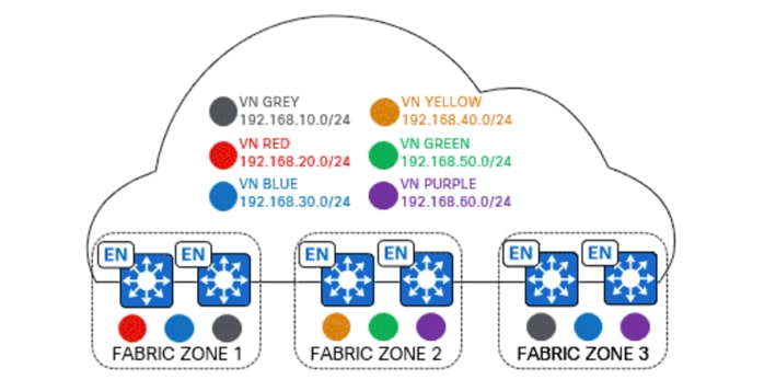
Fabric zones are required for three main reasons:
● Manageability: Solves for large-scale deployments of fabric edge nodes in a single fabric site with a way to manage a network based on smaller locations, or zones (building, floors).
● Security: Provides granular control of VN and IP pool provisioning within a site.
● Scalability and performance: Reduces provisioning time across the fabric edge nodes.
Fabric zones localize Layer 2 VNs and Anycast Gateways to specific sections of a fabric site, such as individual buildings. Fabric zones are optional. They reside within a fabric site and can only contain edge nodes and extended nodes. If fabric zones are used, only specific VNs and Anycast Gateways are provisioned to the edge nodes in each fabric zone.
If fabric zones are not used, all VNs and Anycast Gateways are provisioned to all edge nodes in the fabric site. When a design hierarchy element is moved into a fabric zone, all existing edge nodes provisioned at or below the design hierarchy element are automatically moved into the fabric zone. There is no impact to user traffic when existing edge nodes move into a fabric zone.
The following figure shows an example of a fabric zone configuration:
End-to-end segmentation
Proper end-to-end network segmentation is a foundational measure to address various network security and scalability issues. SD-Access allows network architects to implement secure segmentation for users, devices, and applications across the network, enhancing robustness and scalability. Macrosegmentation and microsegmentation in SD-Access fabric can extend beyond the network by mapping SD-Access VNs to Catalyst SD-WAN VRF context. The SGT carries across Catalyst SD-WAN with inline SGT tagging to have a common end-to-end segmentation.
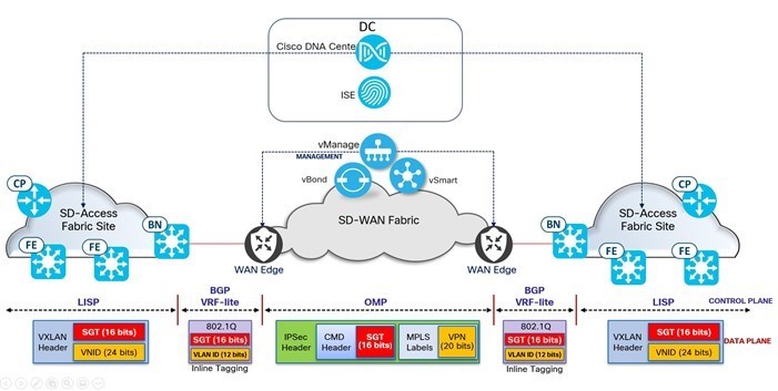
In the Catalyst SD-WAN overlay network, VRFs divide the network into different segments. Segmentation is done at the edges of a router, and the segmentation information is carried in the packets in the form of an identifier. All prefixes belonging to a single VRF are kept in a separate routing table. This provides Layer 3 isolation required for the various segments in the network. In addition, the SD-WAN Controller maintains the VRF context of each prefix. Separate routing tables provide isolation on a single node. Catalyst SD-WAN allows for the application of granular policies on an individual segment (VRF) basis, including Security, QoS, App Aware Routing, and Topology (Hub and Spoke, Full Mesh, Partial Mesh, and so on).
For more details, see Catalyst SD-WAN Segmentation.
The SD-WAN Manager provides network administrators with tools to implement and manage network segmentation. The SD-WAN Manager uses several features and techniques to achieve segmentation.
Security policies
You can implement security policies to control traffic within segments. This includes firewall rules, ACLs, and other security measures to control the flow of traffic between segments.
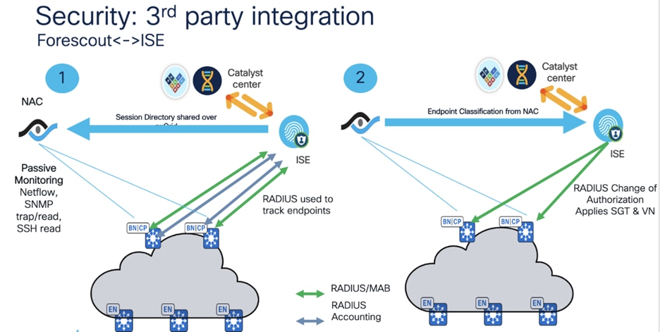
Integrating ISE with the third-party Forescout platform
Integrating ISE with the third-party Forescout platform enhances network security by combining identity-based access control with comprehensive device visibility and management. This integration allows organizations to enforce policies more effectively across their network infrastructure, ensuring greater control and security posture.
● Define Groups: Uses Catalyst Center to create logical groups for protected endpoints based on their access requirements, and applications and services.
● Traffic Observation: Catalyst Center allows for the observation of traffic patterns between these groups, providing visibility into communication flows for effective policy management.
● Leverage ISE Infrastructure: Integrate with ISE to use its geo-resilient deployment capabilities, ensuring continuous service availability across locations.
● SGT Data Sharing: ISE shares SGT data via pxGrid, enabling seamless integration with security applications for optimized policy enforcement.
● Optimized Policy Management: Combined, Catalyst Center and ISE offer automation and identity-driven policies, allowing for dynamic policy adjustments based on real-time context, such as user identity and device type.
This integrated approach enhances security and operational efficiency by leveraging network and security infrastructure for comprehensive policy management and traffic visibility.
Forescout's pxGrid Plugin integrates with existing ISE deployments so that you can benefit from Forescout visibility and assessment for policy decisions while continuing to use ISE as an enforcement point. The pxGrid plugin enables Forescout platform policies to detect ISE-related properties on endpoints, and to apply ISE Adaptive Network Control (ANC) policies, including policies that assign security groups to devices.
This plugin is also known as the Forescout Cisco pxGrid Plugin.
To use the plugin, you should have a solid understanding of ISE concepts, functionality, and terminology, and understand how Forescout Platform policies and other basic features work.
The plugin uses certificates to securely communicate with ISE.
A Forescout platform policy or manual action instructs ISE to apply an ANC policy to devices that the operator selects or that meet Forescout platform policy conditions.
ISE applies a security group to the devices that match the ANC policy.
Cisco switches are configured to allow or deny access to resources for specific SGTs.
For more information about the pxGrid plugin for ISE, see:
https://docs.forescout.com/bundle/pxgrid-1-2-2-h/page/c-about-the-pxgrid-plugin.html
To enable Cisco ISE pxGrid, see:
https://docs.forescout.com/bundle/pxgrid-1-2-2-h/page/c-configure-cisco-ise-for-the-plugin.html#t_pxgrid_12_h_configure_cisco_ise_for_the_pxgrid_plugin
User experience
Assurance and visibility
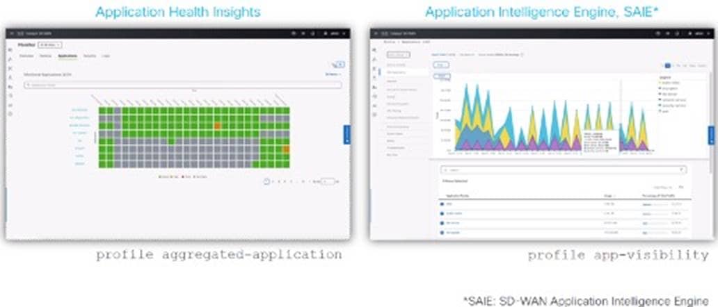
Catalyst SD-WAN offers a unified interface that combines assurance and management capabilities, providing customers with a comprehensive and near real-time view of network and application health, configurations, and security status. The unified dashboard streamlines administrative tasks, minimizes operational complexities, and strengthens network oversight and governance. By leveraging SD-WAN Analytics, customers can synthesize extensive telemetry data, blending application performance insights with network conditions in an intuitive and simplified dashboard. This advanced analytics capability improves network visibility and establishes historical benchmarks, helping customers quickly identify the root cause of any issue. This capability translates to actionable intelligence, full-context alerts, and detailed security insights, enabling NetOps and SecOps teams to effectively safeguard their networks against evolving cyber threats.
The integration of Catalyst SD-WAN and ThousandEyes brings end-to-end visibility into application delivery and network performance beyond traditional enterprise network boundaries. This integration provides the only Catalyst SD-WAN solution with turnkey ThousandEyes vantage points, delivering an optimal application experience over any network. Enterprises and other organizations can expedite the deployment of ThousandEyes agents through an SD-WAN Manager integration.
For more details, see Catalyst SD-WAN Analytics.
Catalyst Center manages your network by automating network devices and services and provides network assurance and analytics capabilities. Catalyst Center collects telemetry from network devices, ISE, users, endpoints, applications, and other integrations across the network. Catalyst Center Network Analytics correlates data from various sources to help administrators and operators offer comprehensive network insight into:
● Device 360 or client 360: View device or client connectivity, including information on topology, throughput, and latency from various times and different applications.
● Network time travel: Review historical data to identify the cause of a network issue.
● Application experience: Provide exceptional visibility and performance control for critical business applications tailored to each user.
● Network analytics: Provide recommended actions for issues found in the network. These actions can involve guided remediation, where the engine provides troubleshooting steps.
For more details, see Catalyst Center Assurance.
Thousand Eyes agent integration
ThousandEyes enables IT organizations to troubleshoot application and user experience issues by providing hop-by-hop visibility across your enterprise, ISP, and Software as a Service (SaaS) provider network. When combined with Catalyst Center insights into the health of networks and users, the ThousandEyes integration provides IT access to powerful diagnostics. Combining Catalyst Center with ThousandEyes, IT administrators can quickly understand the impact and root cause of an application performance issue. Customers can use the Catalyst Center guided workflow to deploy ThousandEyes agents quickly.
For more details, see ThousandEyes and Catalyst Center integration.
The Cisco ThousandEyes Enterprise agent can be deployed natively as a container application on supported Cisco IOS XE Catalyst SD-WAN devices, enabling integration between Catalyst SD-WAN and ThousandEyes. You can install and activate the ThousandEyes Enterprise agent through SD-WAN Manager. By integrating Catalyst SD-WAN with ThousandEyes, you can gain granular insights into network and application performance with full hop-by-hop path analysis across the internet, and you can isolate fault domains for expedited troubleshooting and resolution.
For the configuration guide, see Extended Visibility with Cisco SD-WAN and Cisco ThousandEyes.
IP Address Management server integration
The IP Address Management (IPAM) server integration with Catalyst Center allows viewing the network IP address scopes and identifying the scopes owned by the financial network.
In SD-Access deployments, the IPAM integration provides Catalyst Center access to existing IP address scopes. When configuring new IP address pools in Catalyst Center, it automatically updates the IPAM server, which reduces the management tasks.
For more information about the IPAM server, see the administrator guide.
ServiceNow integration
Catalyst Center and ServiceNow (ITSM) integration supports the following capabilities:
● Manage incidents, events, changes, and problems.
● Manage approval and preapproval chains.
● Manage formal change and maintenance window schedules.
The integration scope is mainly to check your network for assurance and maintenance issues, and for events requiring software image updates for compliance, security, or any other operational triggers. Details about these issues are then published to an ITSM system or any REST endpoint.
For more information about the ServiceNow integration, see the user guide.
Operational
System and network resiliency
The financial vertical solution requires the handling of failures at multiple layers, including low-level device, link failures, controller failures, and data center outages. Catalyst Center provides system resiliency with features such as high availability and disaster recovery. SD-Access and Catalyst SD-WAN also offer network resiliency with support for dual SD-Access borders, dual Catalyst SD-WAN WAN edges, fabric nodes with stacks and StackWise Virtual Link (SVL), and wireless controllers in Stateful Switchover (SSO) and N+1.
Catalyst SD-WAN enhances network resiliency, ensuring that financial organizations maintain connectivity and application performance even in the face of network failures or adverse conditions. This network resiliency is important for business continuity. Catalyst SD-WAN offers the following features and strategies to enhance network resiliency.
Controller redundancy
Catalyst SD-WAN supports the clustering of SD-WAN Manager instances. A minimum of three nodes are required to form a cluster. Each node within a cluster shares configuration and statistics database. A single SD-WAN Manager instance manages up to 2000 Catalyst SD-WAN routers. A three-node SD-WAN Manager cluster manages up to 4000 devices and can tolerate one node failure. SD-WAN Manager maintains configuration and statistics databases for all routers. The configuration and statistics databases are replicated between the cluster members for fault tolerance. If one of the SD-WAN Manager instances fails, the two remaining instances provide the redundancy required to continue to manage the Catalyst SD-WAN routers. The configuration and statistics database must run on all three SD-WAN Manager instances. However, they can be separated. For example, with a cluster of six SD-WAN Manager instances, three of them can maintain the configuration database, and the other three can maintain the statistics database. Managing statistics (when DPI is enabled) can impose a heavy load on an SD-WAN Manager instance. With a cluster, this responsibility can be separated from other services.
For details about designing controller redundancy in Catalyst SD-WAN networks, see the Catalyst SD-WAN HA Design Guide.
Active/active data centers
If financial organizations have multiple data centers (DC), Catalyst SD-WAN edge locations can be configured to maintain active/active connections to each data center with routes from one DC being preferred over the other for data plane traffic in normal conditions. If the preferred DC experiences an outage, traffic is automatically redirected to the other DC, ensuring continuous access to applications and data.
Disaster recovery
Financial institutions have a low tolerance for management, control, or data plane failure. Catalyst Center supports both intracluster and intercluster resiliency. The Catalyst Center Disaster Recovery implementation consists of three components: the main site, the recovery site, and the witness site. At any given time, the main and recovery sites operate in either active or standby roles. The active site manages your network while the standby site maintains a continuously updated copy of the active site's data and managed services. When an active site goes down, Catalyst Center automatically initiates a failover, completing the tasks necessary to designate the former standby site as the new active site.
For more details about disaster recovery, see the Catalyst Center Administrator Guide and Catalyst SD-WAN disaster recovery.
Resilient network architecture
SVL, like its predecessor Virtual Switching System (VSS), addresses and simplifies Layer 2 operations. It is the virtualization of two physical switches into a single logical switch from a control and management plane perspective. It provides the potential to eliminate spanning tree and first-hop redundancy protocol requirements, along with multiple touchpoints to configure those technologies.
Layer 3 routed access moves the Layer 2 and Layer 3 boundary from the distribution layer to the access layer. With the boundary shifted, the distribution and collapsed core layers no longer require handling Layer 2 adjacency and redundancy. This boundary shift means that the network design can focus more on Layer 3 routing, reducing the complexity associated with Layer 2 protocols and redundancy mechanisms. StackWise Virtual simplifies control plane protocols and physical connections, but it requires extra protocols for Layer 2 issues. In a Layer 3 network, it may lead to losing a redundant Interior Gateway Protocol (IGP) or Exterior Gateway Protocol (EGP) control plane instance.
Apart from the conventional means of providing resiliency using stacking and SVL, regional hubs and campus headquarters in financial networks often require protection from building failures. This protection ensures that connectivity to data centers for payment gateways and other critical applications is always available. SD-Access allows for a flexible deployment by enabling fabric borders to be placed in different physical locations while still being a part of a single fabric site.
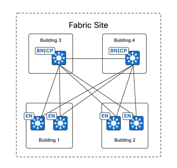
In the preceding figure, Buildings 1 through 4 are in the same fabric site, with the co-located border nodes and control plane nodes located in separate buildings. SD-Access provides the flexibility to assign priorities to these border node deployments so that one border node can be prioritized or become the only active border carrying traffic if it is active. When a building fails, the border node in the other building can automatically take over all traffic from the edge nodes.
WAN redundancy
Multiple connection branches have multiple WAN connections, ensuring continuous connectivity even if links fail. Catalyst SD-WAN dynamically routes traffic based on link performance and availability.
(Optional) Edge device redundancy
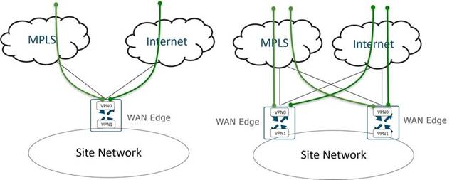
Dual edge device branches may deploy dual Catalyst SD-WAN edge devices in an active/active or active/standby configuration to enhance local redundancy. TLOC-Extensions extend the WAN circuits to peer routers at the same site, offering transport level redundancy on both Catalyst SD-WAN routers.
The following figures are transport options from a WAN edge in a Catalyst SD-WAN.
Fallback segments
SD-Access supports a critical VLAN capability to provide minimum required network connectivity options to endpoints when the connectivity to their ISE server is lost because of outages, such as a WAN outage. For onboarded clients, if connectivity to the ISE policy service node is lost, periodic reauthorization is paused to ensure disruptions in the authentication path do not impact the data plane. For clients that are not yet onboarded into the network, the critical VLAN feature places the client on a special VLAN if connectivity to ISE is lost. This VLAN provides limited access to the network. Critical VLANs can use microsegmentation to enforce the policy in absence of ISE.
Catalyst Center High Availability
Catalyst Center High Availability (HA) framework reduces the amount of failure downtime and makes your network more resilient. The HA framework achieves this by providing near real-time synchronization of changes across your cluster nodes, giving your network a level of redundancy to deal with any issues. Catalyst Center supports a three-node cluster configuration, which provides HA for both software and hardware.
For configuration details, see the Catalyst Center High Availability Guide.
ISE HA
A deployment that has a single ISE node is called a standalone deployment. This node runs the administration, policy service, and monitoring personas. A deployment that has more than one ISE node is called a distributed deployment. To support failover and improve performance, set up multiple ISE nodes in a distributed deployment. In an ISE distributed deployment, administration and monitoring activities are centralized, and processing is distributed across the policy service nodes.
For more details about ISE installation and upgrades, see the Install and Upgrade Guide.
Wireless LAN controller redundancy
The HA SSO feature on the wireless controller allows the AP to connect to the active controller and share its data with the standby controller. When the active controller fails and the standby controller takes over, APs remain connected, and clients do not disconnect. Only one CAPWAP tunnel is maintained with the active wireless controller.
All the control plane activities are centralized and synchronized between the active and standby units. The active controller centrally manages all the control and management communication. The network control data traffic is transparently switched from the standby unit to the active unit for centralized processing.
For more details, see the High Availability SSO Deployment Guide for Cisco Catalyst 9800 Series Wireless Controllers.
Large-scale multisite deployments and centralized policy management
Large-scale multisite deployment refers to the implementation of a system, application, or infrastructure across multiple locations or sites on a significant scale. This approach is often adopted to meet the diverse requirements of organizations with widespread operations across regions. It offers organizations the flexibility, resilience, and scalability. Streamlined policy management from a centralized location can help businesses achieve end-to-end consistent policy management.
Multiple Catalyst Centers to a single ISE cluster
Global deployments spread across various locations require multiple Catalyst Centers to be deployed because of scale considerations, latency network requirements, and global compliance reasons. Multiple Catalyst Center clusters can be integrated into a single ISE system, providing centralization and standardization of authentication, authorization, and security group policy across the global enterprise.
Large ISE deployments, such as in financial networks, can benefit by integrating multiple Catalyst Center clusters with a single ISE system. Catalyst Center supports multiple Catalyst Center clusters for each ISE deployment to use ISE better and provide a centralized policy management plane for multiple Catalyst Centers.
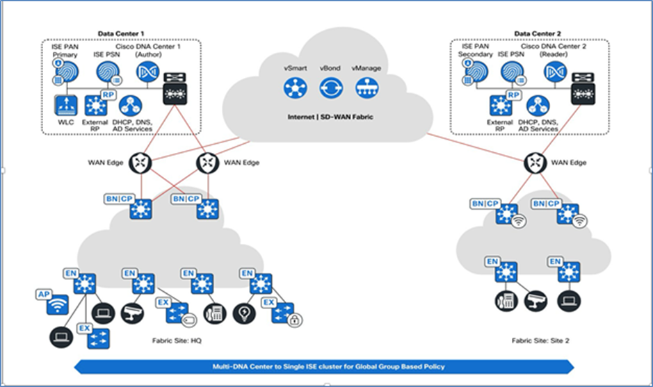
For more details about the processes for multiple Catalyst Center to a single ISE deployment, see the Prescriptive Deployment Guide.
Centralized policy management
To deal with the problems associated with managing the exponential growth in the number of endpoints connecting to the network, design a solution that integrates Bring Your Own Device (BYOD) capabilities. Globally, build a set of security policies that span the globe but are easy to manage and propagate.
Solve these problems with Catalyst Center integrated with ISE, both of which are foundational elements of an SD-Access network. Within the network, enable secure onboarding for endpoints with SD-Access and ISE, using a redirect to a Mobile Device Manager (MDM). After the endpoint is onboarded appropriately, it has all the security policies, security clients, and signatures matching the organization security policies. With SD-Access, enforce compliance with the security policy based on the posture assessment.
After devices are authorized on the network, embed a security tag based on the authorized session and apply a security policy that is enforced end-to-end anywhere in the network.
Globally, Catalyst Center can author policy in one cluster and then absorb that on multiple Catalyst Center clusters around the world allowing for the same policies to be propagated globally. This ability allows building a flexible policy that makes sense and simultaneously scales across the entire global enterprise.
Observationally, with Catalyst Center and SD-Access, evaluate group interactions with Security Group Policy Analytics. Security Group Policy Analytics is a Catalyst Center application that enables identifying which users and devices are interacting within the network, anywhere in the world. If behavior must be corrected immediately, build a contract in Catalyst Center and deploy it globally in minutes.
Policy management in Catalyst SD-WAN allows financial organizations to define and enforce rules that govern how traffic is handled across the network. Deployment and monitoring of centralized policies across the Catalyst SD-WAN fabric is done through Catalyst SD-WAN Manager and executed at the Catalyst SD‑WAN Controller. The following figure shows different policies that can be implemented in a financial organization.
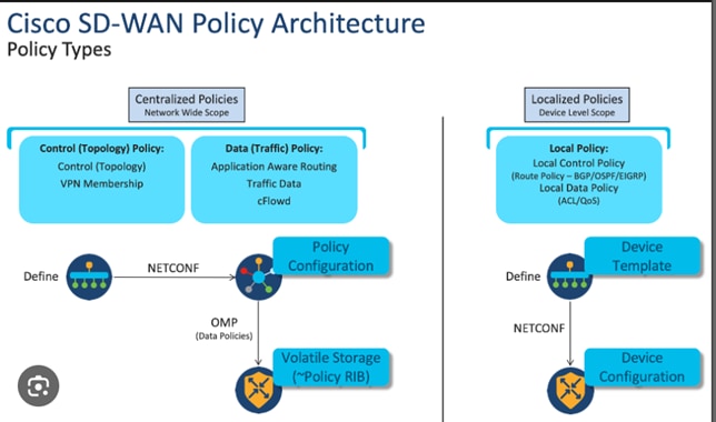
Control policies
Catalyst SD-WAN control policies are essential for defining how traffic is routed and managed across the network. These policies allow network administrators to optimize performance, enforce security, and ensure compliance with organizational requirements. The following list identifies the types of control policies in Catalyst SD-WAN and how they are typically implemented, allowing network administrators to define which sites can connect with each other:
● Traffic engineering policies
● VPN membership policies
● Topology policies
● Traffic filtering policies
Implementation of hub and spoke, full mesh, and partial and regional mesh models are done using control policies. For more details, see Catalyst SD-WAN Control Policy Configuration.
Traffic steering
Policies are used to define how traffic is steered through the network. Create policies that direct specific types of traffic over specific links or paths. For example, send critical business application traffic over a high-performance link while directing guest traffic over a lower-cost link.
Traffic steering in Catalyst SD-WAN is a crucial feature for financial customers, because it ensures that the right traffic gets the right priority and is routed through the most appropriate paths based on performance, cost, and security requirements. Traffic steering can be effectively implemented for financial customers using the following Catalyst SD-WAN features:
● AAR
● Policy-based routing
● Dynamic path selection
● QoS
● SLAs
AAR
Catalyst SD-WAN AAR is a powerful feature that financial institutions can use to ensure their critical applications receive the necessary performance, security, and reliability. Financial customers can use the following features to implement AAR:
● Application identification
● Performance monitoring and SLAs
● Traffic policies and path selection
● QoS and prioritization
● Continuous monitoring and adjustments
These policies allow Catalyst SD-WAN edge devices to select the best path dynamically for application traffic based on the performance requirements of each application.
● SLA compliance: Ensure that applications meet predefined performance metrics.
● Application prioritization: Prioritize traffic based on application type (for example, VoIP video conferencing).
Enabling enhanced AAR on Catalyst SD-WAN edge devices accelerates the detection of tunnel performance issues.
For more details, see the Catalyst SD-WAN Policies Configuration Guide.
Benefits of enhanced AAR
● Improved the Performance Routing (PfR) metrics (loss, latency, and jitter) measurements by introducing inline data that provides more accurate and detailed measurements of these metrics. Inline data refers to the traffic that is processed and inspected directly at the edge of the network, within the Cisco IOS XE Catalyst SD-WAN devices. Instead of routing all the traffic to a central location for analysis and security checks, inline data allows for real-time inspection and decision making at the network edge.
● Quick Enhanced-App-Route Detection and SLA enforcement, which involves reducing the poll interval to a very low value (minimum of 10 seconds). This benefit allows the IOS XE Catalyst SD-WAN devices to detect quickly any slow degradation of circuits. If a circuit fails to meet the SLA threshold, the tunnels are swiftly switched out from SLA forwarding to ensure efficient and reliable network performance. SLA forwarding refers to the capability of the Catalyst SD-WAN solution to route network traffic dynamically based on predefined performance criteria or SLAs.
● Improved speed of SLA switch-over.
● SLA dampening is introduced for a smoother transition to SLA forwarding. Before implementing SLA forwarding, the tunnel goes through a process called dampening, which helps prevent disruptions and instabilities. This benefit ensures a smooth transition back to SLA, minimizing any negative effects on network performance.
● Enhancements are made to measure loss, latency, and jitter.
For more details, see Enhanced Application-Aware Routing.
Custom applications in financial networks
Many financial institutions may have internal and proprietary applications that require priority consideration. These applications can be classified as custom applications on edge devices, and policies can be applied to provide preferential treatment. Catalyst SD-WAN does this using the Software-Defined Application Visibility and Control (SD-AVC) capabilities.
For more information, see the Catalyst SD-WAN Custom Application Guide.
Security policies
You can create policies to enforce security rules and restrictions. This creation might involve implementing firewall rules, ACLs, or VPN policies to protect the network and sensitive data.
With fabric sites and branches throughout the world, Catalyst SD-WAN provides a robust transport for connectivity between an SD-Access site underlay and overlay. Using inline SGT tagging, SGTs are maintained end to end, allowing for consistent policy enforcement throughout the domain and at the fabric edges.
Isolation of guest users
Financial network administrators often manage extensive guest services with a common subnet across all their campus and branch sites. To address this challenge, SD-Access provides the Multisite Remote Border (MSRB) solution using VN anchors. This solution allows traffic from a given VN at multiple dispersed sites to be aggregated back to a central location, also known as an anchor site. At the central location, the VN uses a single common subnet rather than having to define and use individual site subnets for guest traffic.
VN anchor sites significantly simplify guest service deployments across SD-Access fabric sites and provide consistent and secure segmentation for guest traffic in financial environments with a simplified and centralized common subnet structure.
Using anchored services, traffic for guest endpoints that belong to the anchored VN at each site are aggregated and tunneled back to the MSRB at the anchor site over a VXLAN. An anchor site functions much like a traditional fabric site, but it forms a virtual fabric site serving a particular VN.
This virtual fabric site has its own border nodes and control plane nodes that are dedicated to the anchor site. A distinctive feature of the anchor site is that its edge nodes and fabric wireless controllers are dispersed across multiple fabric sites, also known as anchoring sites.
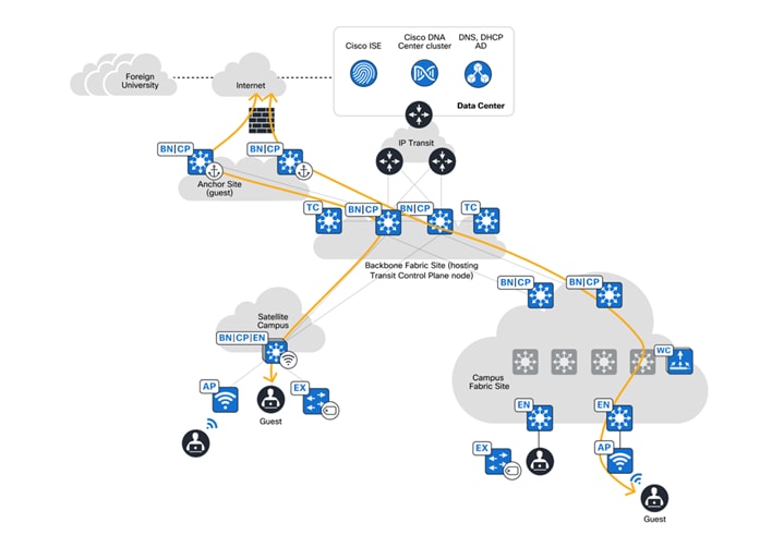
MSRB
MSRB is enabled on each VN. For an anchored VN, all edges in the anchoring sites use the anchor site border nodes and control plane nodes for data plane and control communication. Fabric wireless controllers in the anchoring sites communicate with the anchor site control plane node for wireless endpoint registration specific to the anchored VN. Since the anchor site border node reachability may cross multiple IP networks, make sure that with the MTU across the entire path, the additional VXLAN header overhead of 50 bytes is accommodated.
After a guest endpoint joins the guest SSID and passes the Central Web Authentication (CWA) using ISE, it is associated with the anchored guest VN. Guest traffic is tunneled to the anchor site border node and egresses to the internet through a firewall.
Additionally, while the guest traffic is encapsulated in a VLAN and passes through the fabric, the first-hop or gateway for guest traffic can be outside the fabric and connected at Layer 2 to the MSRB. This device can be a firewall for inspection purposes, if it's a design requirement.
From an ISE perspective, the suggested following options for the financial customers that require isolated guest environments are:
● Separate Policy Service Node (PSN) hosted in a DMZ for guest users
● Dedicated PSN for guest users
By having separate authentication, authorization, and MSRB for the guest user, the guest network is now fully isolated from the control plane, data plane, and policy plane perspective, ensuring the guest network is isolated from the other financial users, devices, and resources.
Guest access automation
Catalyst Center configures CWA, External Web Authentication (EWA), and hotspot SSIDs on Cisco Aire OS and Polaris-based wireless LAN controllers (Catalyst 9800 and embedded wireless on Catalyst 9000 platforms) to enable guest access flow in SD-Access network.
For more details, see Cisco DNA Center SD-Access Guest Automation.
Video streaming across branches and headquarters
Multicast will be required in the SD-Access campus fabric for various trading floor and video applications that exist in a financial environment. Video applications include various advertisements that can be streamed to various branches across various regions to explain new product offerings or programs to visiting customers.
Multicast data can be streamed from a variety of sources, including regional data centers, corporate data centers, and so on. The SD-Access architecture provides the flexibility of end-to-end seamless multicast data traffic to flow from anywhere in the larger enterprise network to anywhere across the globe. This multicast traffic can be streamed over SD-Access transit or IP-based transit networks. SD-Access supports all flavors of multicast, with flexibility in allocating multicast Rendezvous Points (RP) nodes either inside the SD-Access fabric or outside of it.
Multicast is supported in both the overlay VN and the physical underlay networks in SD-Access.
The multicast source can either reside outside the fabric or can be inside fabric overlay. Multicast receivers are commonly directly connected to edge nodes or extended nodes. However, multicast receivers can also be outside of the fabric site if the source is in the overlay. Protocol Independent Multicast with Any-Source Multicast (PIM-ASM) and PIM Source-Specific Multicast (PIM-SSM) are supported. SD-Access supports two different transport methods for forwarding multicast.
● Head-end replication uses the overlay.
● Native multicast uses the underlay.
Head-end replication
Head-end replication (or ingress replication) is done either by the multicast first-hop router (FHR) when the multicast source is in the fabric overlay or by the border nodes when the source is outside the fabric site.
Native multicast
Native multicast does not require the ingress fabric node to do unicast replication. Instead, the whole underlay, including intermediate nodes, is used to do the replication. To support native multicast, the FHRs, last-hop routers (LHRs), and all network infrastructure between them must be enabled for multicast.
Inactive hosts in the branch network
Layer 2 flooding is feature that enables the flooding of broadcast, link-local multicast, and ARP traffic for a given overlay subnet. In traditional networking, broadcasts are flooded out of all ports in the same VLAN. By default, SD-Access transports frames without flooding Layer 2 broadcast and unknown unicast traffic, and other methods are used to address ARP requirements and ensure standard IP communication gets from one endpoint to another.
However, some networks require using broadcast, specifically to support silent hosts, which generally require the reception of an ARP broadcast to come out of silence. This use case is commonly seen in some building management systems (BMS) that have endpoints that must use ARP for one other and receive a direct response at Layer 2. Another common use case for broadcast frames is Wake-On-LAN (WoL) Ethernet broadcasts that occur when the source and destination are in the same subnet.
Because the default suppression of broadcast allows for the use of larger IP address pools, the pool size of the overlay subnet requires careful consideration when Layer 2 flooding is enabled. Consider using a /24 (24-bit netmask) or smaller address pool to limit the number of broadcasts, because each of these frames must be processed by every device in the segment. Layer 2 flooding should be used selectively, where required, by using a small address pool and ensuring it is not enabled by default.
SD-Access multicast over SD-WAN
SD-Access native multicast relies on Source-Specific Multicast (SSM) in the underlay. Therefore, SSM configurations are configured on the fabric nodes and intermediate nodes. The multicast RPs can be external to the SD-Access fabric in the data center or local to fabric. Typically, because most of this kind of streaming happens from the data center, place the RP nodes closer to the sources. Receivers placed across fabric sites can subscribe to multicast traffic over Catalyst SD-WAN. Multicast (SSM with ASM) is enabled on the service VPN subinterfaces of the Catalyst SD-WAN edges towards the overlay VN on the fabric border nodes. This topology ensures a complete end-to-end native multicast configuration throughout the fabric nodes and Catalyst SD-WAN edges.
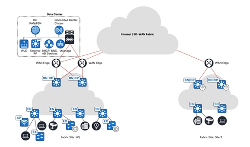
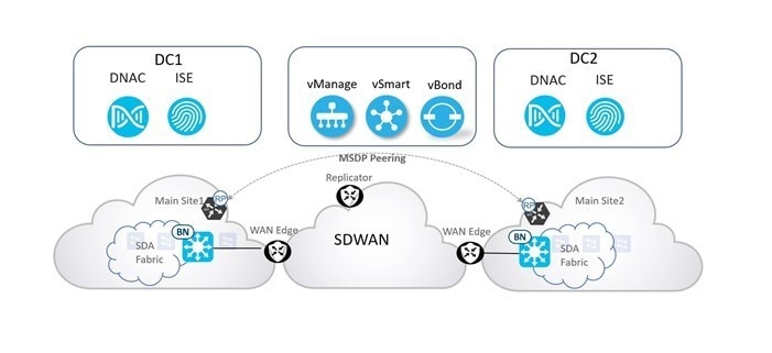
Multicast is enabled on the service VPN subinterfaces of the Catalyst SD-WAN WAN edges, which are connected to the underlay network in the fabric borders. This topology ensures a complete end-to-end native multicast configuration throughout the fabric nodes and Catalyst SD-WAN WAN edges.
Catalyst SD-WAN offers a variety of network services and features to help financial organizations optimize and manage their networks more effectively. These services are designed to improve network performance, security, and overall agility. Some of the key network services available in Catalyst SD-WAN are:
Service chaining
Catalyst SD-WAN service chaining is also known as service insertion. Both terms are used interchangeably. It refers to the capability of inserting one or more network and security services into the path of specific data traffic in an automated manner within the Catalyst SD-WAN overlay fabric.
A common use case for service chaining in financial customer network is regulatory compliance, such as Payment Card Industry Data Security Standard (PCI DSS), where there is a requirement for PCI traffic to flow through firewalls (FW) that might be in a centralized DC or a regional hub. Another use case is to redirect certain traffic flows through a load balancer, a WAN optimization appliance, or a web proxy. Regardless of the type of service, the Catalyst SD-WAN solution supports the deployments and advertisements of different network and security services using templates and a centralized policy in conjunction with OMP. There is also the ability to insert services (FW, Intrusion Detection System (IDS), Intrusion Prevention System (IPS), and so on) on-demand and when certain types of traffic flows are matched.
The key differentiator for the Catalyst SD-WAN service chaining capability is that it is very flexible, fully automated, and can be deployed on each VPN. In a traditional WAN environment, inserting a firewall in the path of specific traffic is typically associated with manually configuring many individual devices. In contrast, the Catalyst SD-WAN service insertion process is as simple as:
1. Matching interesting traffic with a centralized control or data policy.
2. Setting the firewall service as a next hop.
3. Applying the policy to a target site list through a single NETCONF transaction from the SD-WAN Manager to the SD-WAN Controller.
For more details and instructions, see SD-WAN Service Chaining and service chaining configuration.
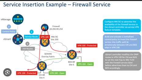
QoS
The QoS capabilities are essential for financial institutions to ensure that critical applications, like trading platforms, online banking, and VoIP services, receive the necessary bandwidth and prioritization. Prioritizing critical applications and ensuring they receive the necessary network resources, Catalyst SD-WAN allows for granular QoS policies at an individual VPN segment-level and advanced adaptive Per‑Tunnel QoS capability. QoS policies can be defined to prioritize certain types of traffic over others. For example, real-time applications, like VoIP or video conferencing, can be given higher priority to ensure low latency and minimal packet loss.
Catalyst SD-WAN Manager can be used to monitor the QoS for each site as shown in the following figure:
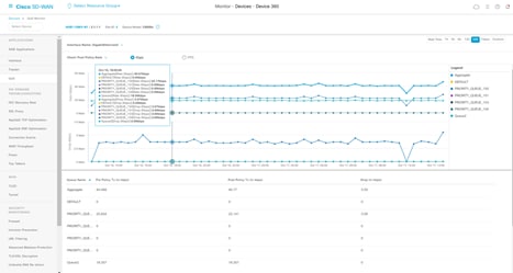
For more details, see the Catalyst SD-WAN Forwarding and QoS Configuration Guide.
Apart from the standard QoS tasks (traffic classification, marking and policing, queuing and scheduling, and bandwidth allocation), the following features can be used to implement advanced QoS for financial organizations by using Catalyst SD-WAN.
Per-tunnel QoS
Per-tunnel QoS can only be applied on hub-to-spoke network topologies. Per-tunnel QoS on a hub lets you shape tunnel traffic to individual spokes. It also differentiates individual data flows going through the tunnel or the spoke for policing.
Benefits of per-tunnel QoS
● A QoS policy is configurable based on session groups. It provides the capability of regulating traffic from hub to spokes at an individual spoke level.
● The hub cannot send excessive traffic to a small spoke and overrun it.
● The maximum outbound bandwidth and QoS queue are set up automatically when each spoke registers with an OMP message.
● The amount of outbound hub bandwidth that a spoke can consume can be limited so that the traffic can’t monopolize a hub’s resources and deprive other spokes.
● Multiple policies (MPoL) are supported. This support enables underlay and TLOC extension traffic to coexist with the overlay tunnel traffic.
For details about configuration and monitoring, see the Per-Tunnel QoS chapter for Catalyst SD-WAN.
Adaptive QoS
Adaptive QoS enables WAN interface shapers and per-tunnel shapers at the enterprise edge to adapt to the available WAN bandwidth. The capability to adapt to the bandwidth controls differentiated packet drops at the enterprise edge and reduces or prevents packet drops in the network core. This capability enables Catalyst SD-WAN edge routers to adjust the shaper parameters dynamically based on the actual available internet bandwidth in both directions, which is periodically computed. This adjustment allows configuring a QoS policy on the spoke towards the hub and ensures better control of application performance at the enterprise edge even when the bandwidth fluctuates. It allows aggregate tunnel shape adaptation to provide effective bandwidth between spoke and hub.
For details about configuration and monitoring, see the Adaptive QoS chapter for Catalyst SD-WAN.
Per-VPN QoS
When a Catalyst SD-WAN edge device receives traffic belonging to different VPNs from the branch network, configure a QoS policy to limit the bandwidth that can be used by the traffic belonging to each VPN or each group of VPNs.
For details about configuration and monitoring, see the Per-VPN QoS chapter for Catalyst SD-WAN.
Benefits of Per-VPN QoS:
● Bandwidth consumption and traffic throughput can be controlled based on the VPN to which the traffic belongs.
● No VPN can use outbound bandwidth beyond each allocated limit, thus preventing it from monopolizing the available resources and depriving other VPNs.
● Different classes of service can be configured for each VPN on a single WAN interface.
High sensitivity to QoS with application policy
Financial organizations have stringent application SLAs, which affect their application availability. A slow and QoS-disparate network can lead to poor application experience and consequently impact operations and trading floors, which are overly sensitive to delays.
Catalyst Center has major advancements which help large and global financial organizations manage and scale application policies for deployment. When building the SD-Access fabric, we can deploy a tiered Cisco-recommended or customized QoS policy to both the wired and wireless infrastructures. This Application policy uses the DiffServ model, where applications are categorized in application sets and are divided into business relevance based on administrator preference.
The advancement of Catalyst Center into Controller-Based Application Recognition uses the Network Based Application Recognition (NBAR) 2.0 Deep Packet Inspection (DPI) capabilities, which are used for Endpoint Analytics. This technology allows Catalyst Center to learn applications directly from packets in transit across the network. This ability allows for seamless learning of applications from a Cisco NBAR 2.0 Cloud, Microsoft 365, and Infoblox. The application's FQDN and URL information can be learned and used to update application sets within QoS policies. This allows for the immediate deployment of those application policies at a scale anywhere in the network.
Catalyst Center also can gather telemetry based on how those application policies are operating, which allows for administrator intervention to modify and redeploy policies at scale across the network. The ability to see how an application operates is crucial to understanding the user experience and solving issues before being notified by an end user, which ensures that we have a method of proving Mean Time to Innocence (MTTI).
Lastly, as all application traffic is now correctly classified and marked by application QoS policies, we can then deal with them appropriately by any device end-to-end in the network, across the WAN, in a SD‑WAN cloud, or even in the data center.
For more details, see the Configure Application Policies chapter.
Application visibility and control
Use DPI and NBAR to identify and prioritize traffic based on specific applications, including custom applications in financial networks.
Catalyst SD-WAN provides robust application visibility and control (AVC) capabilities that are crucial for financial institutions. These features enable financial customers to monitor, manage, and optimize their network traffic effectively, ensuring that critical applications receive the necessary resources and run optimally. The features for implementing and using AVC in Catalyst SD-WAN for financial customers are:
● Application recognition
● Performance monitoring
● Traffic analytics
● Policy enforcement
● Real-time reporting and alerts
Security services
Stateful firewall, IPS, AMP, Unified Threat Defense (UTD) and secure web gateways protect the network and applications from threats.
Cloud integration
Seamless integration with cloud providers such as Amazon Web Services (AWS), Azure, and Google Cloud, make it easier to connect branch offices to cloud resources.
Multicloud connectivity
The ability to connect to multiple cloud providers and manage traffic efficiently.
Policy-based routing
Administrators define policies to control how traffic is routed and managed, ensuring that critical applications get the desired treatment.
Acquisitions integration
Sometimes there are financial organization mergers and acquisitions. SD-Access seamlessly handles these challenges, allowing for the integration and optimization of redundant operations during the merge of two organizations.
After the Business-to-Business (B2B) connection is enabled, merging the two networks can begin. The integration of Catalyst Center and ISE enables the integration of authorization across the SD-Access fabric from one side of the network to the other. By connecting ISE to a foreign Active Directory environment, you can either connect directly or use proxy authentications to onboard clients from the newly merged network. This connection allows for the application of SGTs from one side of the network to the other, which allows for the application of a seamless end-to-end security policy.
Initially, the newly acquired and newly merged organization's endpoints may automatically be placed into a VN within SD-Access and enforcement configured to use a pxGrid integration with firewalls that can enforce policies.
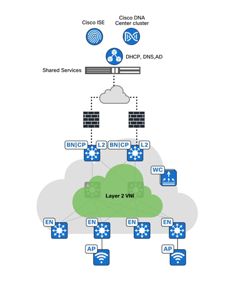
As the acquisition progresses, more integrations can be leveraged, allowing for the slow progression of change of asset ownership and the complete onboarding of the newly acquired and newly merged organization.
Initially, we can deploy a SD-Access fabric as a Layer 2 fabric site and allow for the central onboarding of clients within the fabric site. Those clients use a gateway hosted on a pxGrid-integrated firewall that would initially be responsible for traffic inspection. As confidence improves and the acquisition continues, the client endpoints from the newly acquired organization are onboarded properly within the organization network.
Compliance regulations
RBAC
Catalyst SD-WAN Manager with RBAC is crucial to maintain secure and efficient network management for financial institutions and other organizations. By implementing RBAC, organizations can effectively manage user access, enforce security policies, and maintain compliance with regulatory requirements. This implementation safeguards critical network infrastructure and data.
For more details, see Role Based Access Control.
Catalyst SD-WAN supports the Single Sign-On (SSO) integration with up to three Identity Providers (IdPs) for providing different levels of access for single sign-on users of Catalyst SD-WAN Manager.
For more details about the IdP integration, see Configure Single Sign-On.
Catalyst Center supports the flexibility to assign permissions to users either based on a local or external RADIUS/TACACS database. Users can be assigned one of the following roles and can also be assigned access to specific applications within Catalyst Center:
● Administrator (SUPER-ADMIN-ROLE): Users with this role have full access to all the Catalyst Center functions. They can create other user profiles with various roles, including those with the SUPER-ADMIN-ROLE.
● Network Administrator (NETWORK-ADMIN-ROLE): Users with this role have full access to all the network-related Catalyst Center functions. However, they do not have access to system-related functions, such as backup and restore.
● Observer (OBSERVER-ROLE): Users with this role have view-only access to the Catalyst Center functions. Users with an observer role cannot access any functions that configure or control Catalyst Center or the devices it manages.
For detailed information on user management in Catalyst Center, see the Manage Users chapter in the administrator guide.
Catalyst Center can be configured with RADIUS External Authentication using a Cisco ISE server to manage the controller. For configuration details, see Configure RADIUS External Authentication.
Audit logs
Catalyst SD-WAN offer several benefits specifically tailored for financial customers, such as:
· Regulatory compliance
· Security monitoring
· Forensic analysis
· Accountability and transparency
· Operational insights:
o Configuration changes
o Policy validation
o Alerting and notifications
o Continuous improvement
Overall, audit logs in Catalyst SD-WAN provide financial customers with essential capabilities to maintain security, compliance, operational efficiency, and proactive risk management within their network infrastructure.
For more information on audit logs and exporting them to an external server, see Configure System Logging.
Audit logs capture information about the various applications running on Catalyst Center. Audit logs also capture information about device public key infrastructure (PKI) notifications. The information in these audit logs can be used to help in troubleshooting issues, if any, involving the applications or the device CA certificates.
Additionally, audit logs record system events that occurred, when and where they occurred, and which users initiated them. With audit logging, configuration changes to the system are logged in separate log files for auditing.
For instructions on how to check the audit logs at Catalyst Center, see the Audit logs section.
Configuration compliance
Configuration compliance is crucial for financial customers to ensure network security, adherence to regulatory requirements, and operational consistency. Some of the key capabilities of Catalyst SD-WAN to achieve configuration compliance are Template-Based Configuration and Version Control and Rollback, as well as the ability to lock the router CLI after the device is managed through SD-WAN Manager.
Compliance helps to identify any intent deviation or out-of-band changes in the network that may be injected or reconfigured without affecting the original content.
A network administrator can conveniently identify devices in Catalyst Center that do not meet compliance requirements for the various aspects of compliance, such as software images, Product Security Incident Response Team (PSIRT), network profiles, and so on.
Compliance checks can be automated or performed on demand with scheduling options.
For more details and procedures, see Compliance Audit for Network Devices.
Configuration drift
Financial organizations are often subject to compliance mandates that dictate that organizations maintain archives of configurations for all network devices. Catalyst Center supports configuration drift, which highlights the current configuration of every single device with the flexibility to go back up to a month to view how configurations have changed on a specific device.
Network connectivity and design
Layer 3 external connectivity
Catalyst Center can automate the configuration on the border nodes through an IP-based Layer 3 handoff. This configuration means native IP forwarding is used instead of encapsulation. The fabric packet is de-encapsulated before being forwarded. The configuration is Layer 3, which means that to connect to the upstream peers it uses subinterfaces when the border node is a routing platform or switched virtual interfaces (SVIs) when the border node is a switching platform.
This Layer 3 handoff automation provisions VRF-lite by associating each SVI or subinterface with a different fabric VN (VRF). An external BGP is used as the routing protocol to advertise the endpoint space (EID-space) prefixes from the fabric site to the external routing domain and to attract traffic back to the EID-space. This BGP peering can also be used to advertise routes into the overlay, such as for access to shared services.
While the Layer 3 handoff for external connectivity can be performed manually, automation through Catalyst Center is preferred and recommended.
With the Layer 3 IP-based handoff configured, there are several common configuration options for the next-hop device. This device may have IP connectivity and routing adjacency (peer) with the border node using VRFs. This next-hop device may even continue the VRF segmentation extension to its next hop. This next hop may not be VRF-aware and peer to the border node using the global routing table. Finally, the next hop may be a firewall that is special-case peering that is not VRF-aware.
Layer 2 connectivity with traditional networks
Layer 2 Border Handoff feature provides an overlay service that connects the SD-Access network with the traditional network, enabling hosts in both networks to communicate at Layer 2. When a traditional network is migrating to an SD-Access network, the Layer 2 border handoff is a key strategic feature. Endpoints can stay in the traditional network and communicate with fabric endpoints without requiring IP addresses changes. Hosts can be fully migrated to the fabric by either physically moving cables in a parallel migration or by converting a traditional access switch to an SD-Access fabric edge node in an incremental migration.
The Layer 2 border handoff allows the fabric site and the traditional network VLAN segment to operate using the same subnet. Communication between the SD-Access network and the traditional network is facilitated by the border node, which translates VLANs between the fabric and nonfabric networks. Catalyst Center automates the configuration of the LISP control plane, VLAN translation, SVI, and trunk port on the border node connected to the traditional network.
Multicast is supported across the Layer 2 handoff, allowing multicast communication between the traditional network and the SD-Access network. The multicast forwarding logic at the Layer 2 handoff border node works the same way as it does within the fabric. The traditional network floods multicast packets using standard Layer 2 operations.
Layer 2 border handoff can be used in conjunction with Layer 2 flooding. This conjunction allows Ethernet broadcast Wake on LAN (WoL) between the fabric site and traditional network, enabling systems that use broadcast communication to move into the fabric gradually.
Firewall integration
Common use cases for a firewall peer include internet access, access to data center prefixes, WAN connectivity, or inter-VN communication requirements. In most deployments, endpoints, users, or devices that require direct communication with each other should be placed in the same overlay VN. Some networks may have specific requirements for VN-to-VN communication, though these are less common. VN-to-VN requirements are often during mergers of companies, in some corporate or government structures, or a similar multi-tenant environment where each agency, tenant, or division is required to have their own VN space.
A firewall can be used to provide stateful inspection for inter-VN communication along with providing IPS capabilities, AMP, granular AVC, and even URL filtering. Firewalls such as Cisco ASA and Cisco Firepower Threat Defense (FTD) also provide a rich reporting capability with information on traffic source, destination, usernames, groups, and firewall action with guaranteed logging of permits and drops.
SD-Access transit connectivity for multisite
SD-Access transits are exclusively used in SD-Access for Distributed Campus. Using the SD-Access transit, packets are encapsulated between sites using the fabric VXLAN encapsulation. This transit natively carries the macro (VRF) and micro (SGT) policy constructs between fabric sites.
Transit control plane nodes are a fabric role construct supported in SD-Access for Distributed Campus. It operates in the same manner as a site-local control plane node except it services the entire fabric. Transit control plane nodes are only required when using SD-Access transits.
Each fabric site has their own site-local control plane nodes for intrasite communication, and the entire domain uses the transit control plane nodes for intersite communication. Transit control plane nodes provide the following functions:
● Site aggregate prefix registration: Border nodes connected to the SD-Access transit use a LISP map‑register message to inform the transit control plane nodes of the aggregate prefixes associated with the fabric site. This process creates an aggregate host tracking database (HTDB) for all fabric sites connected to the transit. Rather than a host route being associated with a routing locator (EID-to-RLOC binding), which is what occurs in a site-local control plane node, the transit control plane node associated the aggregate prefix with a border node routing locator (RLOC).
● Control plane signaling: After aggregate prefixes are registered for each fabric site, control-plane signaling is used to direct traffic between the sites. When traffic from an endpoint in one fabric site must send traffic to an endpoint in another site, the transit control plane node is asked which site border node to send the traffic to.
Network deployment options
Fabric site reference models
In deployments with physical locations, customers use different templates for each of the different site types such as a large branch, a regional hub, headquarters, or small, remote office. The underlying design challenge is to look at existing network, deployment, and wiring, and propose a method to layer SD‑Access fabric sites in these areas. This process can be simplified and streamlined by templatizing designs into reference models. The templates drive understanding of common site designs by offering reference categories based on the multidimensional design elements along with endpoint count to provide guidelines for similar site size designs. The numbers are used as guidelines only and do not necessarily match maximum specific scale and performance limits for devices within a reference design.
Fabric in a box deployment
The Fabric in a Box Site Reference Model should target less than 200 endpoints. The principal part of this design is a switch stack or StackWise Virtual operating in all three fabric roles: control plane node, border node, and edge node. For switch stack fabric in a box deployment, SD-Access embedded wireless is used to provide site-local wireless controller functionality. The site may have an ISE Policy Service Node (PSN) depending on the WAN or internet circuit and latency.
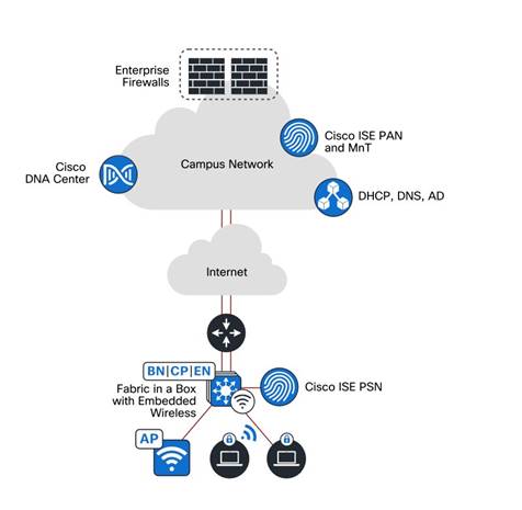
| Network element |
Scale |
| Endpoints, target fewer than |
200 |
| Control plane nodes, colocated |
1 |
| Border nodes, colocated |
1 |
| VNs, target fewer than |
5 |
| IP pools, target fewer than |
8 |
| APs, target fewer than |
40 |
Very small site deployment
The Very Small Site Reference Model should target less than 2000 endpoints. The physical network is usually a two-tier collapsed core and distribution with an access layer servicing several wiring closets. Rather than colocating all roles in one device, the Very Small Site Reference Model provides added resiliency and redundancy along with a larger number of endpoints by separating the edge node role onto dedicated devices in the access layer. The border and control plane node are colocated in the collapsed core layer. For SD-Access wireless, the embedded wireless controller is provisioned on one of the colocated border and control plane nodes. Optionally, a virtual or hardware based wireless controller is used. Provided there are less than 200 APs and 4000 clients, SD-Access embedded wireless can be deployed along with the colocated border node and control plane node functions on a collapsed core switch. For high availability for wireless, hardware or virtual wireless controller should be used.
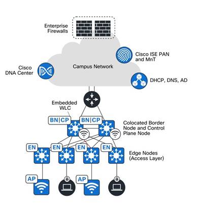
| Network element |
Scale |
| Endpoints, target fewer than |
2000 |
| Fabric nodes, target fewer than |
50 |
| Control plane nodes, colocated |
2 |
| Border nodes, colocated |
2 |
| Virtual networks, target fewer than |
8 |
| IP pools, target fewer than |
20 |
| APs, target fewer than |
100 |
Medium site deployment
The Medium Site Reference Model usually covers a building with multiple wiring closets with a physical topology consisting of a two-tier collapsed core and distribution with an access layer.
The medium site is designed to support less than 25,000 endpoints and less than 2000 APs. The border node and control plane node functions are combined on one or two devices, or on a single highly resilient device. Additionally, a separate wireless controller should be deployed in a HA configuration for optimal performance.
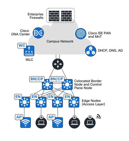
| Network element |
Scale |
| Endpoints, target fewer than |
25,000 |
| Fabric nodes, target fewer than |
450 |
| Control plane nodes |
2-4 |
| Border nodes |
2 |
| Virtual networks, target fewer than |
50 |
| IP pools, target fewer than |
200 |
| APs, target fewer than |
2000 |
Large site deployment
The Large Site Reference Model covers multiple buildings or a building with multiple wiring closets. The physical network is usually three-tier with core, distribution, and access layers. It may even have a routed Super Core that aggregates many buildings and serves as the network egress point to the WAN and internet. The border and control plane nodes are provisioned on separate devices rather than colocating.
The large site supports up to 100,000 endpoints and 6000 APs. The border is distributed using redundant devices from the control plane. A separate wireless controller is in an HA configuration.
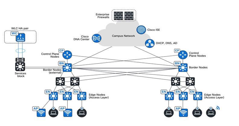
| Network element |
Scale |
| Endpoints, target fewer than |
10,0000 |
| Fabric nodes, target fewer than |
750 |
| Control plane nodes |
2-4 |
| Border nodes (two as Internal and two as External) |
2-4 |
| Virtual networks, target fewer than |
64 |
| IP pools, target fewer than |
450 |
| APs, target fewer than |
6000 |
For more information about the fabric site deployment options, see Reference Models.
Wireless design
SD-Access supports two options for integrating wireless access into the network.
● Use traditional Cisco Unified Wireless Network (CUWN) local-mode configurations with over-the-top (OTT) caching as a non-native service. In this mode, the SD-Access fabric is a transport network for the wireless traffic, which can be useful during migrations to transport CAPWAP-tunneled endpoint traffic from the APs to the wireless controllers.
● Fully integrate SD-Access wireless, extending the SD-Access beyond wired endpoints to also include wireless endpoints.
Integrating the wireless LAN into the fabric provides the same advantages for the wireless clients as provided to the wired clients in the fabric, including addressing simplification, mobility with stretched subnets, and end-to-end segmentation with policy consistency across the wired and wireless domains. Wireless integration also enables the wireless controller to shed data plane forwarding duties while continuing to function as the control plane for the wireless domain.
Fabric wireless controllers manage and control the fabric-mode APs using the same general model as the traditional local-mode controllers which offer the same operational advantages such as mobility control and radio resource management. A significant difference is that client traffic from wireless endpoints is not tunneled from the APs to the wireless controller. Instead, wireless client communication is wrapped in VXLAN by the fabric APs, creating a tunnel to their initial fabric edge node. Wireless traffic goes through tunnels to the edge nodes as the edge nodes provide fabric services such as the Layer 3 anycast gateway, policy, and traffic enforcement. For more details, see the Cisco Wireless Deployment Guide and SD-Access Wireless Design.
Distributed site design
SD-Access for a Distributed Campus is a metro-area solution that connects multiple, independent fabric sites together while maintaining the security policy constructs for VRFs and SGTs across these sites. While multisite environments and deployments have supported SD-Access, there has not been an automated and simple way to maintain policy between sites. At each site fabric border node, fabric packets were de-encapsulated into native IPs. Combined with the Security Group Exchange Protocol (SXP), the policy could be carried between sites using native encapsulation. However, this policy configuration was manual, mandated use of SXP to extend policy between sites, and involved complex mappings of IP-to-SGTs bindings within the ISE.
With SD-Access for Distributed Campus, SXP is not required, the configurations are automated, and the complex mappings are simplified. This solution enables intersite communication using consistent, end-to-end automation and policy across the metro network.
SD-Access for Distributed Campus uses control plane signaling from the LISP and keeps packets in the fabric VXLAN encapsulation between fabric sites. This design maintains the macrosegmentation and microsegmentation policy constructs of VRFs and SGT, respectively, between fabric sites. The original Ethernet header of the packet is preserved to enable the Layer 2 overlay service of SD-Access wireless. The result is a network that is address-agnostic because the policy is maintained through group membership. For more details, see the SD-Access Distributed Campus Deployment Guide and SD-Access Distributed Campus Design.
SD-Access 2.0 publisher and subscriber design
The LISP publisher and subscriber (Pub/Sub) feature eliminates the requirement for an additional protocol to register the LISP site registration table for the control plane nodes in the fabric. It is fully automated through Catalyst Center. Deploying an SD-Access fabric becomes more automated, eliminating the requirement for manual routing configuration.
LISP Pub/Sub architecture is a building block for other features and capabilities, including:
● LISP dynamic default border node
● LISP backup internet
● LISP affinity-ID
● LISP extranet
LISP Pub/Sub is based on publishing and subscribing to routing information. The edge nodes subscribe to the default route, which has the next-hop IPs of both border nodes. When a border node loses the upstream connection (and BGP peering) the default route is also removed from the routing table for the affected VNs. The border node then updates the control plane so that it is no longer used for the default route. The control plane updates all the edge nodes that have subscribed to the default route so that the failed route to a border node is no longer used. The edge with the default route towards the border remains available. This routing mechanism removes the manual configuration requirement to have a BGP peering each VRF and VN between the border nodes to provide routing redundancy.
LISP Pub/Sub recommendation
● LISP/BGP fabric sites and LISP Pub/Sub fabric sites cannot coexist with the same transit control plane nodes.
● Migration from one to another is not supported yet.
● LISP Pub/Sub is recommended only for new network implementation.
Catalyst SD-WAN site references
Large-size and regional branch sites
Sites have dual active circuits from different regional MPLS carriers, with internet (wired broadband or public LTE/5G) connectivity on both routers to provide additional bandwidth and an additional layer of high availability. Large and regional branch sites are critical to financial organizations, and therefore require the deployment of dual routers for WAN access.
Medium-size branch sites
Sites typically have either one MPLS circuit from a regional carrier along with internet (wired broadband or public LTE and 5G) connectivity, or dual MPLS circuits from two regional carriers. In either scenario, both circuits are actively used. Typically, medium-sized branch sites do not deploy dual routers. These sites have single router with dual WAN termination.
Small-size branch sites
These vary widely from a single ATM or small kiosk, offering limited financial services. Generally, a single circuit, either MPLS or internet (wired broadband or LTE and 5G), is provisioned according to what was available at the site. A single router with integrated switch ports is typically deployed within small branch sites. When the number of required switch ports exceeds the number of ports on the integrated switch, a small standalone Layer 2 switch may be deployed along with the router.
For more details, see the Catalyst SD-WAN Large Global WAN Design Case Study.
Migration
For guidelines and recommendations for building a new greenfield deployment of an SD-Access fabric that addresses the challenges and use cases of a finance network deployment, the following sections explain the SD-Access fabric components and the benefits SD-Access solutions offer to address the financials requirements and challenges.
Traditional networks can be managed by Cisco Prime Infrastructure. They can also be managed now with Catalyst Center. Catalyst Center can be used automate, monitor, and gather telemetry for traditional networks as well as SD-Access. If you have an existing network managed by Cisco Prime Infrastructure and are looking to migrate to Catalyst Center, see the Cisco Prime Infrastructure to Catalyst Center Migration Guide.
To migrate existing Catalyst legacy networks to the SD-Access fabric, continue to the Migration section, which provides options to migrate an existing network with both wired and wireless endpoints.
Migration to Catalyst SD-WAN
Migrating from traditional routing to Catalyst SD-WAN for financial customers involves several key considerations and steps to ensure a smooth transition while enhancing network capabilities and security.
For more details, see the Catalyst SD-WAN Migration Guide and the IWAN to Catalyst SD-WAN Migration Guide, which is an older guide, but the methodologies can be the same.
Financial customer migration process outline:
Assessment and planning
● Network Audit: Conduct a comprehensive audit of the existing network infrastructure, including hardware, software, and configurations.
● Traffic Analysis: Analyze traffic patterns, application dependencies, and performance requirements to identify critical applications and their network paths.
● Risk Assessment: Evaluate potential risks and challenges associated with the migration process, such as downtime, data integrity, and compliance requirements.
Design and architecture
● Catalyst SD-WAN Solution Design: Develop a detailed design plan for implementing Catalyst SD-WAN architecture tailored to the financial customer requirements.
● Topology Mapping: Define the new Catalyst SD-WAN topology, including deployment of vEdge routers, controllers (SD-WAN Controller and SD-WAN Manager), and edge devices (cEdge routers).
● Security Integration: Integrate security measures such as firewall policies, VPN configurations, and encryption protocols to ensure data protection during the migration.
Implementation phases
● Pilot Deployment: Deploy a pilot Catalyst SD-WAN environment in a controlled setting to validate the design, functionality, and performance before the full-scale deployment.
● Phased Rollout: Implement Catalyst SD-WAN gradually across different branches or sites, starting with less critical locations to refine processes and address early challenges.
● Configuration Migration: Migrate existing routing configurations to Catalyst SD-WAN templates and policies, ensuring consistency and compliance with business requirements.
● Testing and Validation: Conduct thorough testing of Catalyst SD-WAN functionality, including failover scenarios, application performance, and security measures.
Integration and optimization
● Network Convergence: Integrate Catalyst SD-WAN with existing network infrastructure, ensuring seamless connectivity and interoperability between legacy systems and Catalyst SD-WAN components.
● Performance Optimization: Fine-tune Catalyst SD-WAN policies and QoS settings to optimize application performance, prioritize critical traffic, and improve overall network efficiency.
● Monitoring and Management: Implement centralized monitoring and management tools (for example, SD-WAN Manager) to monitor network health, analyze performance metrics, and troubleshoot issues proactively.
Migration to SD-Access
Greenfield networks have the advantage that the network can be designed as new from the ground up. Brownfield networks are less flexible because of existing constraints like geography and configurations. The aim is to convert them into SD-Access networks, requiring detailed information and planning before migration.
Consider the following list before beginning the migration of an existing network to SD-Access:
● Network considerations: Maximum transmission unit (MTU), network topology, IP addressing for underlay and overlay, and location of shared services.
● Policy considerations: Existing policy definition and enforcement points, VN, and Security Group Tags (SGTs).
● Hardware platform considerations: Switches, routers, wireless controllers, and APs that support SD‑Access.
● Software platform considerations: Catalyst Center, ISE, Network Data Platform
● Scale of deployment considerations: Scale of hardware platforms on their role in the SD-Access architecture.
● Existing network design: Layer 2 access or routed access.
There are two ways of approaching migration:
● A parallel approach involves establishing a new network that is parallel to the existing network. For a parallel install, prerequisites, such as space, power, cooling, and cabling must be available to satisfy parallel live connections. This approach makes the migration easier, with the ability to revert to the existing network if required, but it is also the most expensive because there are two live networks that consume power and space while the migration completes.
● Migrating one switch at a time allows incremental migration of certain areas of the network rather than migrating all devices at once. It is not dependent on factors, such as space, power, and cabling, and is cheaper than the parallel approach. Network administrators can test services and connections with fewer devices by setting up a small SD-Access deployment alongside the existing network, allowing them to explore user scenarios efficiently.
For complete guidance and different options about migrating existing traditional networks to SD-Access, see the “Migration to Cisco SD-Access” chapter in Cisco Software-Defined Access for Industry Verticals: From Design to Migration.
Options to migrate existing brownfield networks with the configuration onto SD-Access fabric are in development.
Validated solution use cases and topology
The following sections describe some of the important use cases validated for financial networks. Organizations can construct their IT/OT infrastructure with certainty, knowing that these designs have undergone thorough testing and are tailored to fulfill business requirements effectively.
The following figure illustrates the logical topology of the solution test bed.
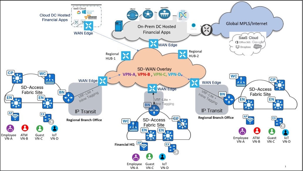
Day zero and day one bring up use cases
● Set up the hub and branches at a greenfield campus and create a robust network infrastructure.
● Upgrade a brownfield campus by migrating existing sites, introduce new network services, ensure minimum disruption, and achieve seamless integration with existing infrastructure.
● Automate and simplify network device and fabric provisioning, including onboarding devices using PnP, zero-touch provisioning (ZTP), and bootstrap methods.
● Integrate with Cisco ISE for robust device and client authentication, covering wired, wireless and Catalyst SD‑WAN routing devices.
● Monitor inventory and manage network devices including wireless controllers and APs in the branch and hub locations using Catalyst Center and SD-WAN Manager.
● Push day-zero configuration templates to manage multiple sites using Catalyst Center and SD-WAN Manager.
Day-n network operations
● Upgrade multiple devices, such as switches, routers, and wireless controllers using Catalyst Center and SD-WAN Manager.
● Migrate from legacy devices to Catalyst SD-WAN and Cisco SD-Access fabric ensuring seamless integration and functionality.
● Manage RMA processes for network devices and controllers to minimize downtime and maintain operational continuity.
● Introduce ISE PSN changes in site to move AAA from one PSN to another PSN.
● Change day-n credentials, including changing ISE password, changing device password, and updating network devices to enhance security.
● Change a brownfield certificate by implementing a refresh of third-party Root CA certificates to ensure security and compliance in the existing deployment.
● Modify data and control policies to meet new requirements specific to the financial sector using a controller.
● Implement new RBAC policies to meet updated requirements and enhance access control and security measures within the network infrastructure.
● Capture and store system events and audit logs for auditing and troubleshooting. Implement robust AAA mechanisms for secure access control. Use SNMP for gathering important legacy data and monitoring network performance metrics.
● Enable real-time streaming telemetry to gather detailed network performance data for advanced monitoring and analysis.
● Set up alerts and notifications for critical network events to ensure proactive management and rapid response.
Segmentation and policy
● Achieve consistent macrosegmentation through VNs and SD-WAN VPN membership lists across the organization.
● Implement end-to-end microsegmentation using group-based access policy with SGTs.
● Ensure propagation of SGTs across the Catalyst SD-WAN overlay.
● Secure onboarding of wired and wireless clients.
● Cover operational scenarios for the addition of new segments and group-based access policy for devices and users.
● Optimize performance of critical financial applications, such as trading platforms and financial analytics, using video streaming and user traffic from hub-to-branch sites across different regions for real-time data synchronization and low-latency transactions.
● Enforce policies and utilize policy-based routing to control traffic paths through the network based on defined policies.
● Use topology control to optimize network performance and management, incorporating access lists to manage and secure network traffic for optimized dataflow across the organization.
● Implement Catalyst SD-WAN specifically tailored for financial customers using direct internet access (DIA).
● Support remote work and employee mobility by providing secure, reliable access to financial applications from any geographic location.
Security use cases
● Implement MACsec to ensure secure communication and data integrity across the network that provides robust protection for sensitive financial data.
● Isolate untrusted traffic to a central location, such as a firewall or a DMZ using MSRB.
● Apply and use trusted certification authority (CA) FQDN-based certificates with network devices and controllers.
● Integrate Stealthwatch with Catalyst Center for threat detection, threat containment, and system administrators (SSA) for encrypted traffic analytics (ETA) automation.
● Create granular role-based users with external Authentication, Authorization, and Accounting (AAA), and use audit logging to check network infrastructure activities.
● Monitor audit policy changes, deployment of policy changes, and the deployment status for the changes.
● Implement zone-based firewall rules tailored for financial institutions to secure network traffic and protect sensitive data.
● Integrate the IDS and the IPS capabilities into the Catalyst SD-WAN to enhance security posture and protect against cyber threats.
● Implement robust UTD mechanisms in the Catalyst SD-WAN fabric to safeguard financial networks against various cyber threats to ensure comprehensive security across all branches and headquarters.
● Deploy service chaining within the Catalyst SD-WAN to direct traffic through an external firewall for enhanced security and policy enforcement in financial network environments.
● Integrate secure service edge (SSE) capabilities into the Catalyst SD-WAN fabric to enhance security, optimize performance, and provide consistent access control and policy enforcement across distributed financial networks.
● Implement NAT to conceal internal network addresses from external threats, ensuring confidentiality and security.
● Use ACLs to restrict traffic flow based on predefined rules to enhance network security by preventing unauthorized access and mitigating potential threats.
● Isolate rogue client and APs using Intelligent Capture on Catalyst Center.
● Isolate rouge Catalyst SD-WAN devices and sites using certificate revocation from the SD-WAN Manager.
SD-Access Wireless LAN
● Wireless clients onboarding uses enterprise SSID for branch employees and users.
● Guest wireless access for users coming into the branches use the Central Web Authentication portal.
● Wireless Infrastructure in HA mode uses either a 9800 Cisco Wireless Controller or an embedded wireless controller.
● Guest SSID traffic enforcement on a firewall uses a multisite remote border.
● QoS for Bring Your Own Device (BYOD) and guest wireless clients in branches use AP groups on APs.
High availability
● Multiple SD-Access controllers across regions with the same ISE use the distributed deployment model for consistent policy management.
● Cluster deployments of SD-WAN Manager are based on scale guidelines.
● Robust disaster recovery solutions are enabled to ensure seamless connectivity between primary and backup data centers.
● Dual-router deployments at critical locations within the financial network ensure redundancy and HA for critical services, load balancing and traffic optimization across multiple paths and seamless failover in case of a router or a link failure.
● Dual-stack deployments on campus provide redundant connections between primary and secondary data centers across different regions to ensure continuous operation in case of a regional outage.
Robustness
● Recover automatically from device or link failure with minimal impact on existing applications, traffic, and user experience.
● Trigger disaster recovery and automatic failover to redundant instances for failover capability, ensuring redundancy and geographical resilience across distinct locations.
● Enable ISE distributed nodes failover with PSN and pxGrid node failover.
● Facilitate Catalyst wireless LAN controller and APs failover.
● Address node failure scenarios in a clustered controller deployment.
● Perform controller configuration and data backup and restore, either at one time or on a schedule.
● Ensure policy and device connectivity longevity amidst network churn.
Monitoring and troubleshooting with Assurance and Analytics
● Monitor the state of the network, wired users, and wireless users from a single management platform, ensuring the reliability and security of the financial network using monitoring dashboards.
● Monitor severe, critical, and other ongoing issues with the network and devices, and follow the suggested actions in Assurance and Analytics to resolve the issues.
● View a device 360 window for a single device, a wired user, or a wireless user, and retrieve detailed information.
● Monitor detailed user application data use and performance using AVC and resolve issues.
● View and troubleshoot network devices through the integration of the ThousandEyes agent.
● Monitor application performance and use patterns, detailed traffic analysis and reporting through DPI with NBAR, Flexible NetFlow (FNF), and the Cflowd flow analysis tool.
● Troubleshoot the network device and client connectivity issues using the integrated tools on the controller, such as Network-Wide Path Insights (NWPI), Underlay Measurement and Tracing Services (UMTS), path trace, machine reasoning engine, and so on.
Scale considerations
The solution tests have confirmed the scalability figures outlined in the following table. For the hardware ability, see the Catalyst Center Data Sheets.
| Attribute |
Value |
| Maximum devices in inventory |
5000 |
| Maximum number of devices for each fabric site |
1 to 500 |
| Maximum number of VNs for each site |
64 |
| Maximum number of wireless controllers for each site |
2 with HA |
| Maximum number of fabric sites |
2000 |
| Maximum number of APs for each site |
1000 |
| Maximum number of endpoints |
300,000 |
| Maximum number of SSIDs |
4 |
| Maximum number of SGTs |
500 |
| Maximum number of APs |
10,000 |
| Maximum number of IP pools for each site |
1000 |
| Multiple Catalyst Center to a single ISE system |
5 Catalyst Center |
| Group-based policies |
25,000 |
For scale considerations and sizing details, see the Catalyst SD-WAN Control Components Compatibility Matrix and Recommended Computing Resources.
| SD-WAN controller scale |
|
| SD-WAN Manager Device inventory |
12,500 (6-node cluster) |
| SD-WAN policy scale (number of lines) |
60,000 |
| cEdge scale* |
Branch (8130-G2) |
Hub 8500-20X6C |
| BFD IPSEC tunnels |
200 |
12,000 |
| VRFs |
10 |
64 |
| DPI flows |
32,000 |
2,000,000 |
| OMP routes |
50,000 |
300,000 |
| Multicast PIM neighbors |
10 |
10 |
| Maximum NAT sessions |
20,000 |
2,000,000 |
| FW sessions |
4,000 |
2,000,000 |
Hardware and software matrix
The solution is tested with the hardware and software listed in the following table. For the complete list of supported hardware, see the Software-Defined Access Compatibility Matrix and Catalyst SD-WAN Control Components Compatibility Matrix and Recommended Computing Resources.
Catalyst SD-WAN and SD-Access hardware and software release matrix:
| Component |
Hardware type |
Software version |
Software version |
| Cisco Catalyst Center controller |
DN2-HW-APL-L, DN3-HW-APL-XL |
2.3.7.9 |
2.3.7.10 |
| Cisco Identity Service Engine management, RADIUS server |
Physical and virtual appliance |
3.3 Patch 4 |
3.4 Patch 3 |
| Cisco Catalyst SD-WAN NMS controller |
SD-WAN Manager |
20.15.3 |
20.18.2.1 |
| Cisco SD-Access control plane node |
C9400, C9500, and C9600 |
17.9.6a, 17.12.5, 17.15.3 |
17.12.6, 17.15.4d, 17.18.3 |
| Cisco SD-Access fabric border node |
C9400, C9500, and C9600 |
17.9.6a, 17.12.5, 17.15.3 |
17.12.6, 17.15.4d, 17.18.3 |
| Cisco SD-Access fabric edge node |
C9200, C9300, and C9400 |
17.9.6a, 17.12.5, 17.15.3 |
17.12.6, 17.15.4d, 17.18.3 |
| Cisco Wireless Controller |
C9800-40 |
17.9.6, 17.12.5 |
17.12.6 |
| Cisco Catalyst SD-WAN WAN edge |
C8200, C8300, and C8500 |
17.15.3a |
17.15.4, 17.12.5a, 17.18.2 |
| Cisco Stealthwatch controller |
Physical and virtual appliance |
7.3.2 |
7.3.2 |
Network as Code (NaC) for efficient deployments:
The Financial network deployments embrace a Network as Code (NaC) approach, ensuring consistent, scalable, and repeatable configurations for financial sector infrastructure. By leveraging Ansible Playbooks specifically developed for Cisco Catalyst Center-based deployments, we automate the key stages of the deployment lifecycle, such as sites expansion, routine maintenance, configuration changes, software upgrades, and health monitoring. This automation significantly reduces manual effort and the potential for human error, while also enhancing operational efficiency, accelerating change implementation, and aligning with modern DevOps principles for agile network management.
To learn more about our network automation practices, we encourage you to explore our automation repository. It features practical examples, reusable Ansible Playbooks tailored for financial network deployments, and proven best practices designed to support scalable, efficient network operations. Visit the repository to gain deeper insights and begin your automation journey with confidence.
For more details, see the repository:
https://github.com/DNACENSolutions/NetworkasCode_CVPs
https://github.com/DNACENSolutions/NetworkasCode_CVPs/tree/main/nac_financial_sda
References and best practices
● Cisco SD-Access Solution Design Guide (Cisco Validated Design)
● Cisco Catalyst Center User Role Permissions
● Support for Multiple Cisco Catalyst Center Clusters with a Single Cisco ISE System
● Cisco Catalyst Center Release Notes
● Cisco Catalyst SD-WAN Design Guide
● Cisco Catalyst SD-WAN End-to-End Deployment Guide
● Cisco Catalyst SD-WAN: Application-Aware Routing Deployment Guide
● Cisco Catalyst SD-WAN: Enabling Direct Internet Access
● Cisco SD-Access | SD-WAN Independent Domain Pairwise Integration
● Zscaler Internet Access (ZIA) and Cisco Catalyst SD-WAN
● Cisco Catalyst Center Security Best Practices Guide