Cisco Catalyst SD-WAN Design Guide
Available Languages
Bias-Free Language
The documentation set for this product strives to use bias-free language. For the purposes of this documentation set, bias-free is defined as language that does not imply discrimination based on age, disability, gender, racial identity, ethnic identity, sexual orientation, socioeconomic status, and intersectionality. Exceptions may be present in the documentation due to language that is hardcoded in the user interfaces of the product software, language used based on RFP documentation, or language that is used by a referenced third-party product. Learn more about how Cisco is using Inclusive Language.
- US/Canada 800-553-2447
- Worldwide Support Phone Numbers
- All Tools
 Feedback
 Feedback
The enterprise landscape is continuously evolving. There is a greater demand for mobile and Internet-of-Things (IoT) device traffic, SaaS applications, and cloud adoption. In addition, security needs are increasing and applications are requiring prioritization and optimization, and as this complexity grows, there is a push to reduce costs and operating expenses. High availability and scale continue to be important.
Legacy WAN architectures are facing major challenges under this evolving landscape. Legacy WAN architectures typically consist of multiple MPLS transports, or an MPLS paired with an Internet or LTE used in an active/backup fashion, most often with Internet or software-as-a-service (SaaS) traffic being backhauled to a central data center or regional hub for Internet access. Issues with these architectures include insufficient bandwidth along with high bandwidth costs, application downtime, poor SaaS performance, complex operations, complex workflows for cloud connectivity, long deployment times and policy changes, limited application visibility, and difficulty in securing the network.
In recent years, software-defined wide-area networking (SD-WAN) solutions have evolved to address these challenges. SD-WAN is part of a broader technology of software-defined networking (SDN). SDN is a centralized approach to network management which abstracts away the underlying network infrastructure from its applications. This de-coupling of data plane forwarding and control plane allows you to centralize the intelligence of the network and allows for more network automation, operations simplification, and centralized provisioning, monitoring, and troubleshooting. SD-WAN applies these principles of SDN to the WAN.
The Cisco® SD-WAN solution is an enterprise-grade WAN architecture overlay that enables digital and cloud transformation for enterprises. It fully integrates routing, security, centralized policy, and orchestration into large-scale networks. It is multitenant, cloud-delivered, highly automated, secure, scalable, and application-aware with rich analytics. The Cisco Catalyst SD-WAN technology addresses the problems and challenges of common WAN deployments. Some of the benefits include:
● Centralized network and policy management, as well as operational simplicity, resulting in reduced change control and deployment times.
● A mix of MPLS and low-cost broadband or any combination of transports in an active/active fashion, optimizing capacity and reducing bandwidth costs.
● A transport-independent overlay that extends to the data center, branch, and cloud.
● Deployment flexibility. Due to the separation of the control plane and data plane, control components can be deployed on premises or in the cloud. Cisco WAN Edge router deployment can be physical or virtual and can be deployed anywhere in the network.
● Robust and comprehensive security, which includes strong encryption of data, end-to-end network segmentation, router and control component certificate identity with a zero-trust security model, control plane protection, application firewall, and insertion of Cisco Umbrella™, firewalls, and other network services.
● Seamless connectivity to the public cloud and movement of the WAN edge to the branch.
● Application visibility and recognition in addition to application-aware policies with real-time service-level agreement (SLA) enforcement.
● Dynamic optimization of SaaS applications, resulting in improved application performance for users.
● Rich analytics with visibility into applications and infrastructure, which enables rapid troubleshooting and assists in forecasting and analysis for effective resource planning.
This design guide provides an overview of the Cisco Catalyst SD-WAN solution. It discusses the architecture and components of the solution, including control plane, data plane, routing, authentication, and onboarding of SD-WAN devices. It covers redundancy of SD-WAN components and discusses many WAN Edge deployment considerations and common scenarios. It also focuses on NAT, Firewall, and other deployment planning considerations.
The intended audience is for anyone who wants a better understanding of the Cisco Catalyst SD-WAN solution, especially network architects that need to understand the workings and deployment best practices in order to make good design choices for an organization’s Cisco Catalyst SD-WAN implementation.
This design guide is a companion guide to the associated prescriptive deployment guides for SD-WAN, which provide details on deploying the most common SD-WAN use cases. The guide is based on SD-WAN Manager version 20.6 and below. The topics in this guide are not exhaustive. Lower-level technical details for some topics can be found in the companion prescriptive deployment guides or in other white papers. See Appendix A for a list of documentation and other references.
Note that there may be feature and capability differences between the two major platform choices for Cisco Catalyst SD-WAN, vEdge and IOS XE SDWAN WAN Edge devices. Some differences and limitations may be pointed out in the guide, but be certain to check the Cisco Feature Navigator for support information before planning your SD-WAN deployment. In addition, please review the software release notes for more information on the specific software release before deploying.
| Tech tip |
| End-of-Life and End-of-Sale Notices have been released for the vEdge platforms. The 20.6 release is the last supported software release for the vEdge 100s and vEdge 1000s. The 20.9 release is the last supported software release for the vEdge 2000s, 5000s, and vEdge Cloud routers. |
There are four major use case categories for the Cisco Catalyst SD-WAN solution:
| Use Case |
Description |
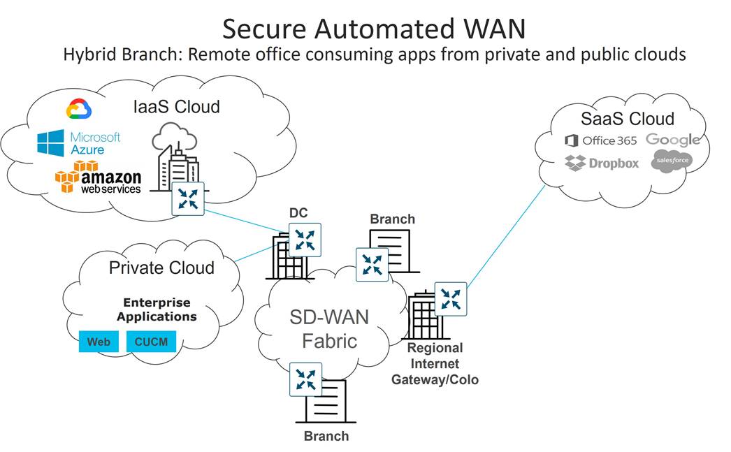
| Secure Automated WAN |
Secure connectivity between remote offices, data centers, and public/private cloud over a transport independent network |
| Application Performance Optimization |
Improves the application experience for users at remote offices |
| Secure Direct Internet Access |
Locally offloads Internet traffic at the remote office |
| Multicloud Connectivity |
Connects remote offices with cloud (SaaS and IaaS) applications over an optimal path and through regional colocation/exchange points where security services can be applied. |
Secure Automated WAN
The secure automated WAN use case focuses on providing the secure connectivity between branches, data centers, colocations, and public and private clouds over a transport independent network. It also covers streamlined device deployment using ubiquitous and scalable polices and templates, as well as automated, no-touch provisioning for new installations.
The following are just a sampling of use cases associated with this category:
● Automated Zero-Touch Provisioning: The ability to remotely provision a router anywhere in the WAN by just connecting it with a cable to the transport network and powering it on. The WAN Edge router discovers its control components automatically and fully authenticates to them and automatically downloads its prepared configuration before proceeding to establish IPsec tunnels with the rest of the existing network. Automated provisioning helps to lower IT costs.
● Bandwidth Augmentation: Allows customers to increase WAN bandwidth by leveraging all available WAN transports and routing capabilities to distribute traffic across available paths in an active/active fashion. Traffic can be offloaded from higher quality, more expensive circuits like MPLS to broadband circuits which can achieve the same availability and performance for a fraction of the cost. Application availability is maximized through performance monitoring and proactive rerouting around impairments.
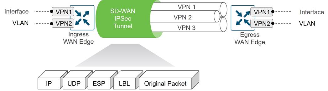
● VPN Segmentation: Traffic isolation is key to any security strategy. Traffic that enters the router is assigned to a VPN, which not only isolates user traffic, but also provides routing table isolation. This ensures that a user in one VPN cannot transmit data to another VPN unless explicitly configured to do so. When traffic is transmitted across the WAN, a label is inserted after the ESP header to identify the VPN that the user’s traffic belongs to when it reaches the remote destination.
● Centralized Management: SD-WAN Manager offers centralized fault, configuration, accounting, performance, and security management as a single pane of glass for Day 0, Day 1, and Day 2 operations. SD-WAN Manager offers operational simplicity and streamlines deployment by using ubiquitous policies and templates, resulting in reduced change control and deployment times.
Application Performance Optimization
There are a variety of different network issues that can impact the application performance for end-users, which can include packet loss, congested WAN circuits, high latency WAN links, and suboptimal WAN path selection. Optimizing the application experience is critical in order to achieve high user productivity. The Cisco Catalyst SD-WAN solution can minimize loss, jitter, and delay and overcome WAN latency and forwarding errors to optimize application performance.
The following Cisco Catalyst SD-WAN capabilities helps to address application performance optimization:
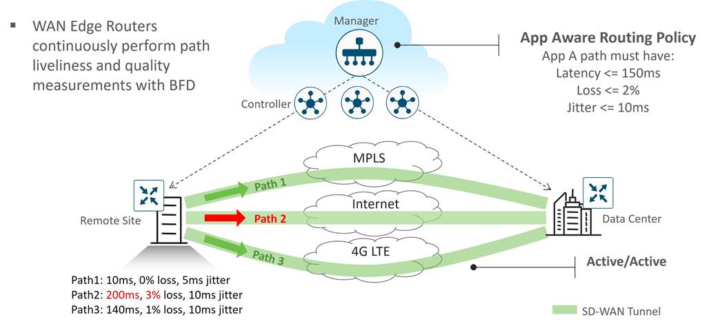
● Application-Aware Routing: Application-aware routing allows the ability to create customized SLA-policies for traffic and measures real-time performance taken by BFD probes. The application traffic is directed to WAN links that support the SLAs for that application. During periods of performance degradation, the traffic can be directed to other paths if SLAs are exceeded.
The figure below shows that for application A, path 1 and 3 are valid paths, but path 2 does not meet the SLAs so it is not used in path selection for transporting application A traffic.
● Quality of Service (QoS): QoS includes classification, scheduling, queueing, shaping and policing of traffic on the WAN router interfaces. Together, the feature is designed to minimize the delay, jitter and packet loss of critical application flows.
● Forward Error Correction (FEC) and Packet Duplication: Both features are used for packet loss mitigation. With FEC, the transmitting WAN Edge inserts a parity packet for every four data packets, and the receiving WAN Edge can reconstruct a lost packet based on the parity value. With packet duplication, the transmitting WAN Edge replicates all packets for selected critical applications over two tunnels at a time, and the receiving WAN Edge reconstructs critical application flows and discards the duplicate packets.
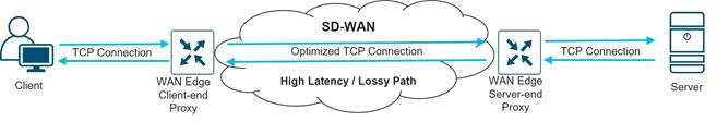
● TCP optimization and Session Persistence: These features can address high latency and poor throughput for long-haul or high latency satellite links, for example. With TCP optimization, a WAN Edge router acts as a TCP proxy between a client and server. With Session Persistence, instead of a new connection for every single TCP request and response pair, a single TCP connection is used to send and receive multiple requests and responses.
● Data Redundancy Elimination (DRE): This feature is a type of TCP optimization using compression technology that removes redundant information, thus reducing the size of the transmitted data across the WAN. The receiving end can reconstruct the data stream before sending it on to its destination.
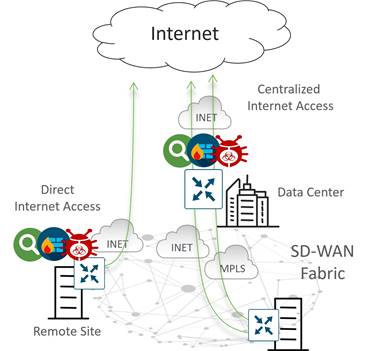
Secure Direct Internet Access
In traditional WAN, Internet traffic from a branch site is backhauled to a central data center site, where the traffic can be scrubbed by a security stack before the return traffic is sent back to the branch. Over time, demand for Internet traffic has been increasing as more companies are utilizing cloud services for their applications and more applications are becoming Internet-based. Backhauling traffic to a central site causes increased bandwidth utilization for the security and network devices and links at the central site, as well as increased latency which has an impact on application performance.
Direct Internet Access (DIA) can help solve these issues by allowing Internet-bound traffic from a VPN (either all traffic or a subset of traffic) to locally exit the remote site.
DIA can pose security challenges as remote site traffic needs security against Internet threats. Cisco Catalyst SD-WAN can help solve this by leveraging the embedded SD-WAN security features on IOS XE SD-WAN devices or by leveraging a Secure Access Service Edge (SASE) model with Umbrella Cloud, Cisco’s Secure Internet Gateway (SIG). SASE offers secure application access to users anywhere by consolidating multiple networking and security functions into a single integrated cloud service.
IOS XE SD-WAN security features include Enterprise Application-Aware Firewall, Intrusion Detection System (IDS)/Intrusion Prevention System (IPS), DNS/Web Layer Security, URL Filtering, SSL Proxy, and Advanced Malware Protection (AMP). vEdge routers natively support an application-aware firewall. The Cisco Umbrella Cloud unifies several security features and delivers them as a cloud-based service. These features include a secure web gateway, DNS-layer security, cloud-delivered firewall, cloud access security broker functionality, and threat intelligence. The Cisco SASE model also includes Cisco Duo, which offers two-factor authentication and endpoint security, and Cisco Thousand Eyes, which offers Internet and Cloud visibility to assure exceptional user application experiences.
Cisco Catalyst SD-WAN routers can also connect to other third-party Secure Internet Gateway (SIG) providers. With Zscaler, multiple tunnels can be provisioned automatically to help the user deploy quickly with minimal configuration, which is also a current benefit of deploying with Umbrella SIG.
Multicloud Connectivity
Applications are moving to multiple clouds and are reachable over multiple transports. The Multicloud Connectivity use case category deals with how to connect IaaS or SaaS cloud applications to remote sites over optimal paths, as well as how to connect to them through regional colocation/exchange points where security services can be applied.
The following use cases are associated with this category:
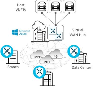
● Infrastructure-as-a-Service (IaaS): IaaS delivers network, compute, and storage resources to end users on-demand, available in a public cloud (such as AWS, Azure, or Google Cloud) over the Internet. Traditionally, for a branch to reach IaaS resources, there was no direct access to public cloud data centers, as they typically require access through a data center or colocation site. In addition, there was a dependency on MPLS to reach IaaS resources at private cloud data centers with no consistent segmentation or QoS policies from the branch to the public cloud.
Cisco Cloud onRamp for Multicloud (formally Cloud onRamp for IaaS) is a feature that automates connectivity to workloads in the public cloud from the data center or branch. It automatically deploys WAN Edge router instances in the public cloud that become part of the SD-WAN overlay and establish data plane connectivity to the routers located in the data center or branch. It extends full SD-WAN capabilities into the cloud and extends a common policy framework across the SD-WAN fabric and cloud. Cisco Cloud onRamp for Multicloud eliminates traffic from SD-WAN sites needing to traverse the data center, improving the performance of the applications hosted in the public cloud.
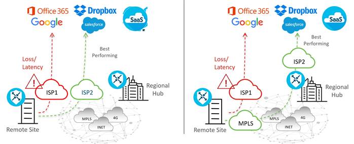
● Software-as-a-Service (SaaS): Traditionally, branches have accessed SaaS applications (Salesforce, Box, Office 365, etc.) through centralized data centers, which results in increased application latency and unpredictable user experience. As SD-WAN has evolved, additional network paths to access SaaS applications are possible, including Direct Internet Access and access through regional gateways or colocation sites. However, network administrators may have limited or no visibility into the performance of the SaaS applications from remote sites, so, choosing what network path to access the SaaS applications in order to optimize the end-user experience can be problematic. In addition, when changes to the network or impairment occurs, there may not be an easy way to move affected applications to an alternate path.
Cloud onRamp for SaaS allows you to easily configure access to SaaS applications, either direct from the Internet or through gateway locations. It continuously probes, measures, and monitors the performance of each path to each SaaS application, and it chooses the best-performing path based on loss and delay. If impairment occurs, SaaS traffic is dynamically and intelligently moved to the updated optimal path.
In addition to basic benefits from Cloud onRamp for SaaS, there have been several new features to improve the integration between SD-WAN Cloud onRamp for SaaS and Office 365, which gives users more insightful metrics, more control over traffic flow for individual O365 applications, and automatic remediation of suboptimal performance taking into account Microsoft telemetry metrics.
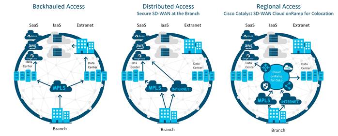
● Regional Multicloud Access: Traditional WAN utilizes the backhauling of traffic to a central site and relies on the centralized provisioning of security devices there to scrub traffic, which results in increased bandwidth requirements at the central site and increased latency for applications. DIA helps alleviate these issues and improves the user experience by allowing branch users to access Internet resources and SaaS applications directly from the branch. While this distributed approach is efficient and greatly beneficial, there are many organizations who are prohibited from accessing the Internet from the branch, due to regulatory agencies or company security policy.
For these organizations, Cloud onRamp for Colocation allows for a hybrid approach to the problem by utilizing co-locations in strategic points of the network to consolidate network and security stacks and minimize latency. Colocation centers are public data centers where organizations can rent equipment space and connect to a variety of network and cloud service providers. Colocations, which are strategically selected for close proximity to end users, get high-speed access to public and private cloud resources and are more cost effective than using a private data center.
 In the colocations, multiple network functions (such as WAN Edge routers, proxies, firewalls, load-balancers, IDS/IPS, etc.) can be virtualized. These services are announced to the rest of the SD-WAN network, and control and data polices can be used to influence traffic through these colocation resources if needed.
● Software-Defined Cloud Interconnect (SDCI)
There can be challenges connecting Enterprise sites to cloud infrastructure and giving users a high-quality application experience in a reliable and cost-effective way. Traditionally, transports like Internet and MPLS are used to connect sites and sites to cloud applications, but these connections may be unreliable and insecure. Even MPLS transports may not be available everywhere and may take some time to set up. SDCI is used both to interconnect sites and connect sites to cloud infrastructures through geographically dispersed Points of Presence (PoPs) which can allow customers to build a dedicated network segment or "middle mile". Customers can use transports of their choice to the nearest SDCI provider POP, using SDWAN to optimize traffic, and then traffic can flow onto the backbone of the SDCI provider. SDCI provides reliable and dedicated secure bandwidth that is cost effective and offers onboarding that is quick and flexible and requires no additional hardware investment by the customer.
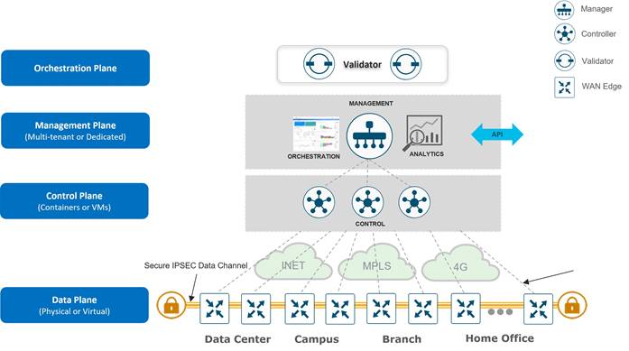
The Cisco Catalyst SD-WAN solution is comprised of separate orchestration, management, control, and data planes.
● The orchestration plane assists in the automatic onboarding of the SD-WAN routers into the SD-WAN overlay.
● The management plane is responsible for central configuration and monitoring.
● The control plane builds and maintains the network topology and makes decisions on where traffic flows.
● The data plane is responsible for forwarding packets based on decisions from the control plane.
Components
| Tech tip |
| Cisco SD-WAN has been rebranded to Cisco Catalyst SD-WAN. As part of this rebranding, the vManage name has been changed to SD-WAN Manager, the vSmart name has been changed to SD-WAN Controller, and the vBond name has been changed to SD-WAN Validator. Together, the vManage, vSmart, and vBond will be referred to as the SD-WAN control components in this document. |
The primary components for the Cisco Catalyst SD-WAN solution consist of the SD-WAN Manager network management system (management plane), the SD-WAN Controller (control plane), the SD-WAN Validator (orchestration plane), and the WAN Edge router (data plane).
● SD-WAN Manager - This centralized network management system is software-based and provides a GUI interface to easily monitor, configure, and maintain all Cisco Catalyst SD-WAN devices and their connected links in the underlay and overlay network. It provides a single pane of glass for Day 0, Day 1, and Day 2 operations.
● SD-WAN Controller - This software-based component is responsible for the centralized control plane of the SD-WAN network. It maintains a secure connection to each WAN Edge router and distributes routes and policy information via the Overlay Management Protocol (OMP), acting as a route reflector. It also orchestrates the secure data plane connectivity between the WAN Edge routers by reflecting crypto key information originating from WAN Edge routers, allowing for a very scalable, IKE-less architecture.
● SD-WAN Validator - This software-based component performs the initial authentication of WAN Edge devices and orchestrates SD-WAN Controller, Manager, and WAN Edge connectivity. It also has an important role in enabling the communication between devices that sit behind Network Address Translation (NAT).
● WAN Edge router - This device, available as either a hardware appliance or software-based router, sits at a physical site or in the cloud and provides secure data plane connectivity among the sites over one or more WAN transports. It is responsible for traffic forwarding, security, encryption, quality of service (QoS), routing protocols such as Border Gateway Protocol (BGP) and Open Shortest Path First (OSPF), and more.
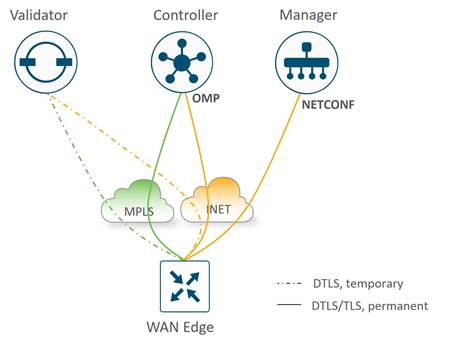
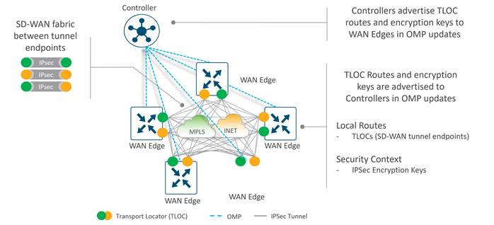
The following diagram demonstrates several aspects of the Cisco Catalyst SD-WAN solution. This sample topology depicts two WAN Edge sites, each directly connected to a private MPLS transport and a public Internet transport. The cloud-based SD-WAN control components (the two SD-WAN Controllers, the SD-WAN Validator, along with the SD-WAN Manager) are reachable directly through the Internet transport. In addition, the topology also includes cloud access to SaaS and IaaS applications.
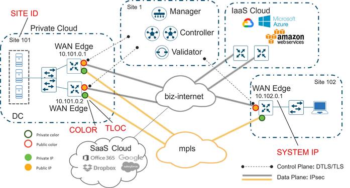
The WAN Edge routers form a permanent Datagram Transport Layer Security (DTLS) or Transport Layer Security (TLS) control connection to the SD-WAN Controllers and connect to both of the SD-WAN Controllers over each transport. The routers also form a permanent DTLS or TLS control connection to the SD-WAN Manager, but over just one of the transports. The WAN Edge routers securely communicate to other WAN Edge routers using IPsec tunnels over each transport. The Bidirectional Forwarding Detection (BFD) protocol is enabled by default and runs over each of these tunnels, detecting loss, latency, jitter, and path failures.
Site ID
A site ID is a unique identifier of a site in the SD-WAN overlay network with a numeric value 1 through 4294967295 (2^32-1) and it identifies the source location of an advertised prefix. This ID must be configured on every WAN Edge device, including the control components, and must be the same for all WAN Edge devices that reside at the same site. A site could be a data center, a branch office, a campus, or something similar. By default, IPsec tunnels are not formed between WAN Edge routers within the same site which share the same site-id.
System IP
A System IP is a persistent, system-level IPv4 address that uniquely identifies the device independently of any interface addresses. It acts much like a router ID, so it doesn't need to be advertised or known by the underlay. It is assigned to the system interface that resides in VPN 0 and is never advertised. A best practice, however, is to assign this system IP address to a loopback interface and advertise it in any service VPN. It can then be used as a source IP address for SNMP and logging, making it easier to correlate network events with SD-WAN Manager information.
Organization Name
Organization Name is a name that is assigned to the SD-WAN overlay. It is case-sensitive and must match the organization name configured on all the SD-WAN devices in the overlay. It is used to define the Organization Unit (OU) field to match in the Certificate Authentication process when an SD-WAN device is brought into the overlay network.
Public and Private IP Addresses
Private IP Address
On WAN Edge routers, the private IP address is the IP address assigned to the interface of the SD-WAN device. This is the pre-NAT address, and despite the name, can be a public address (publicly routable) or a private address (RFC 1918).
Public IP Address
The Post-NAT address detected by the SD-WAN Validator. This address can be either a public address (publicly routable) or a private address (RFC 1918). In the absence of NAT, the private and public IP address of the SD-WAN device are the same.
TLOC
A TLOC, or Transport Location, is the attachment point where a WAN Edge router connects to the WAN transport network. A TLOC is uniquely identified and represented by a three-tuple, consisting of system IP address, link color, and encapsulation (Generic Routing Encapsulation [GRE] or IPsec).
Color
The color attribute applies to WAN Edge routers or SD-WAN Managers and Controllers and helps to identify an individual TLOC; different TLOCs are assigned different color labels. The example SD-WAN topology in figure 10 uses a public color called biz-internet for the Internet transport TLOC and a private color called mpls for the other transport TLOC. You cannot use the same color twice on a single WAN Edge router.
Overlay Management Protocol (OMP)
The OMP routing protocol, which has a structure similar to BGP, manages the SD-WAN overlay network. The protocol runs between SD-WAN Controllers and between SD-WAN Controllers and WAN Edge routers where control plane information, such as route prefixes, next-hop routes, crypto keys, and policy information, is exchanged over a secure DTLS or TLS connection. The SD-WAN Controller acts similar to a BGP route reflector; it receives routes from WAN Edge routers, processes and applies any policy to them, and then advertises the routes to other WAN Edge routers in the overlay network.
Virtual private networks (VPNs)
In the SD-WAN overlay, virtual private networks (VPNs) provide segmentation, much like Virtual Routing and Forwarding instances (VRFs) that many are already familiar with. Each VPN is isolated from one another and each have their own forwarding table. An interface or subinterface is explicitly configured under a single VPN and cannot be part of more than one VPN. Labels are used in OMP route attributes and in the packet encapsulation, which identifies the VPN a packet belongs to.
The VPN number is a four-byte integer with a value from 0 to 65535, but several VPNs are reserved for internal use, so the maximum VPN that can or should be configured is 65527. There are two main VPNs present by default in the WAN Edge devices and control components, VPN 0 and VPN 512. Note that VPN 0 and 512 are the only VPNs that can be configured on the SD-WAN Manager and the SD-WAN Controllers. For the SD-WAN Validator, although more VPNs can be configured, only VPN 0 and 512 are functional and the only ones that should be used.
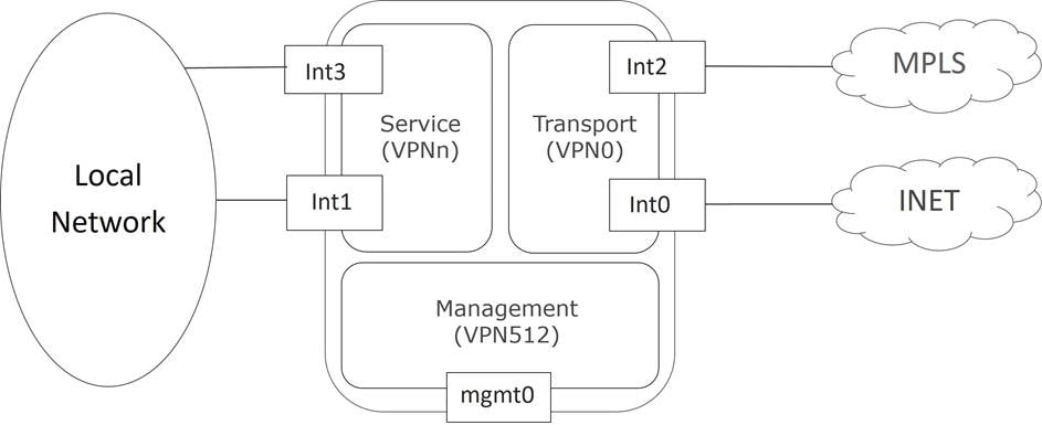
● VPN 0 is the transport VPN. It contains the interfaces that connect to the WAN transports. Secure DTLS/TLS connections to the control components are initiated from this VPN. Static or default routes or a dynamic routing protocol needs to be configured inside this VPN in order to get appropriate next-hop information so the control plane can be established and IPsec tunnel traffic can reach remote sites.
● VPN 512 is the management VPN. It carries the out-of-band management traffic to and from the Cisco Catalyst SD-WAN devices. This VPN is ignored by OMP and not carried across the overlay network.
In addition to the default VPNs that are already defined, one or more service-side VPNs need to be created that contain interfaces that connect to the local-site network and carry user data traffic. It is recommended to select service VPNs in the range of 1-511, but higher values can be chosen as long as they do not overlap with default and reserved VPNs. Service VPNs can be enabled for features such as OSPF or BGP, Virtual Router Redundancy Protocol (VRRP), QoS, traffic shaping, or policing. User traffic can be directed over the IPsec tunnels to other sites by redistributing OMP routes received from the SD-WAN Controllers at the site into the service-side VPN routing protocol. In turn, routes from the local site can be advertised to other sites by advertising the service VPN routes into the OMP routing protocol, which is sent to the SD-WAN Controllers and redistributed to the other WAN Edge routers in the network.
The following figure demonstrates VPNs on a WAN Edge router. The interfaces, Int0 and Int2, are part of the transport VPN; Int1 and Int3 are part of the service VPN, which is attached to the local network at the site; and the mgmt0 port is part of VPN 512.
| Tech tip |
| Note that any interface could also be a subinterface. In that case, the main (or parent) physical interface that the subinterface belongs to must be configured in VPN 0. In vEdge routers (all code versions) and IOS XE SD-WAN routers (code versions prior to 17.4.1), the subinterface MTU must be 4 bytes lower than the physical interface due to the 802.1Q tag. The recommendation is to set the main interface MTU to 1504 and leave the subinterface MTU at default (1500). MTU configuration is not required for IOS XE SD-WAN routers running 17.4.1 or later. |
Note: The above illustrates how VPNs are represented directly on the vEdge router and through the SD-WAN Manager configuration. When configurations get pushed from the SD-WAN Manager to the IOS XE SD-WAN routers, they are automatically converted into a format accepted by the IOS XE SD-WAN software parser. Some differences include:
● VRF terminology is used instead of the VPN keyword
● The global table is used to represent VPN 0
● VRF Mgmt-intf is enabled by default on the management interface and is used to represent VPN 512
| Tech tip |
| While IOS XE routers accept names for VRF definitions, with IOS XE SD-WAN code, VRF definitions must be numbers only. |
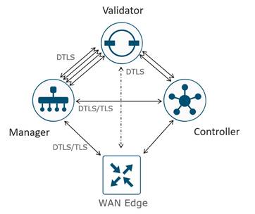
Control Connections
The Cisco Catalyst SD-WAN Manager and Controllers initially contact and authenticate to the SD-WAN Validator, forming persistent DTLS connections, and then subsequently establish and maintain persistent DTLS/TLS connections with each other. WAN Edge devices onboard in a similar manner but drop the transient SD-WAN Validator connection and maintain DTLS/TLS connections with the SD-WAN Manager and Controllers. The following diagram illustrates this:
| Tech tip |
| Control connections to the SD-WAN Validator are always DTLS. By default, connections to the SD-WAN Manager and Controller are DTLS as well, but this can be changed on any device by configuring TLS for the security control protocol. If one device is configured for TLS and another device is configured for DTLS, TLS is chosen for the control connection between the two devices. TLS uses TCP, which uses acknowledgments for greater reliability. TCP is also connection-oriented, so firewalls can maintain the state of the connections and allow return traffic without explicitly having to allow the traffic. |
Note: Each core (up to a maximum of 8) on the SD-WAN Manager and Controller initiates and maintains a control connection to each SD-WAN Validator (which has a single core), while a single connection is maintained between the SD-WAN Manager and each SD-WAN Controller. If an SD-WAN Controller has 2 vCPUs (which translates into 2 cores), for example, there will be 2 total control connections maintained from the SD-WAN Controller to each Validator, one from each core. If an SD-WAN Manager has 4 vCPUs (which translates to 4 cores), there will be 4 total control connections maintained from the SD-WAN Manager to each Validator, one from each core. Only one control connection is formed between Controllers, and only one connection is formed between SD-WAN Managers. No control connections are formed between redundant SD-WAN Validators.
WAN Edge Control Connections
The WAN Edge router tries to establish control connections over all provisioned transports by default, first initiating contact with the SD-WAN Validator over each transport before attempting to connect to the other control components. Only one SD-WAN Validator control connection is made per transport when multiple Validators exist. Transports are tried one at a time, typically starting with the transport connected to the lowest port number. The WAN Edge router establishes a permanent connection to the SD-WAN Controller over each transport, and establishes a single, permanent connection to the SD-WAN Manager over only one transport, the first one which establishes a connection. The SD-WAN Validator connection is then terminated. Note that a WAN Edge router does not have to connect to every SD-WAN Controller, it depends on the network redundancy design and configurations. Technically, a single connection to an SD-WAN Controller over one transport is sufficient for a WAN Edge router to receive control plane information, but for redundancy purposes, additional SD-WAN Controllers over multiple transports are typically configured. When a WAN Edge router connects to an SD-WAN Manager cluster, the control connection is hashed to one SD-WAN Manager instance and does not need to establish connections with all members.
It is important to note that if WAN Edge routers are not able to connect to the proper number of control components (DTLS/TLS to the SD-WAN manager, DTLS/TLS connections per transport to each of two Controllers, and 1 OMP session to each of the two Controllers by default), then the WAN Edge connections are considered “out of equilibrium”. When this occurs, the WAN Edge establishes a permanent connection over the TLOC to the Validator until the correct number of control connections have been re-established.
| If all SD-WAN Controller connections are lost, the WAN Edge router continues to operate with the latest control plane information for the length of the OMP graceful restart timer (12 hours by default). |
Once a secure connection is built, NETCONF is used by the SD-WAN Manager to provision the WAN Edge device, and OMP peering is established between the SD-WAN Controller and WAN Edge. Note that OMP peering is established using the system IP addresses and only one peering session is established between a WAN Edge device and an SD-WAN Controller, even if multiple DTLS/TLS connections exist.
| Since there is only one transport used for the connection to the SD-WAN Manager, you can influence the transport preference by setting the vmanage-connection-preference parameter to a higher value under the tunnel interface. The default value is 5. The value 0 is used to indicate that a connection is never made to the SD-WAN Manager over the tunnel. This is often implemented on metered links, like LTE. |
Control Connection Summary
The following summarizes the control connections for the control components and WAN Edge routers:
● Permanent DTLS connections between each SD-WAN Controller core (up to 8) and each SD-WAN Validator
● Permanent DTLS connections between each SD-WAN Manager core (up to 8) and each SD-WAN Validator
● A permanent TLS or DTLS connection between each SD-WAN Manager and each SD-WAN Controller
● Full mesh of TLS or DTLS connections between SD-WAN Controllers (1 connection between each pair)
● Full mesh of TLS or DTLS connections between SD-WAN Manager cluster instances (1 connection between each pair)*
● Temporary DTLS connection between each WAN Edge and one SD-WAN Validator – one connection on each transport
● Permanent TLS or DTLS connection between each WAN Edge and one SD-WAN Manager instance – only one connection over one transport is chosen
● Permanent TLS or DTLS connections between each WAN Edge and two SD-WAN Controllers by default – connections to each over each transport**
*For SD-WAN Manager cluster instances, some instances that are dedicated to statistics as an example and do not handle WAN Edge devices can be configured without tunnel interfaces and thus, no control connections are built to those instances.
**For SD-WAN Controllers, the number of connections depend on the max-control-connections and max-omp-sessions configurations on the WAN Edge router.
Authorized List Model
All WAN Edge devices and control components mutually authenticate each other using an authorized list model, where the devices have to be authorized before establishing connections and being allowed access onto the network.
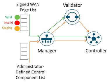
There are two authorized lists that are distributed by the SD-WAN Manager, one for the control components and one for WAN Edge devices.
● Authorized control component list: The authorized control component list is a result of the administrator adding the control components manually into the SD-WAN Manager user interface. This list can be distributed from the SD-WAN Manager to the control components and, subsequently, from the SD-WAN Validator to the SD-WAN Controllers.
● Authorized serial number list for WAN Edge devices: The digitally-signed authorized serial number list for the WAN Edge devices can be modified and retrieved from the Plug and Play Connect portal at http://software.cisco.com. The list can be retrieved manually or synced automatically from the SD-WAN Manager by a user with a valid Cisco CCO account with access to the proper Smart Account and Virtual Account for the SD-WAN overlay. As of 20.3.1, unsigned authorized serial number lists using .CSV files are also supported, which does not require access to the Plug and Play portal. After the file is uploaded or synced to the SD-WAN Manager, it is distributed by the SD-WAN Manager to all the control components. With the WAN Edge authorized serial number list, the administrator can decide and configure the identity trust of each individual WAN Edge router. The options are:
◦ Valid: The router is authorized to be fully operational in the SD-WAN network.
◦ Invalid: The router is not authorized in the SD-WAN network, so no control connections form with the control components.
◦ Staging: The router can authenticate and form control connections with the control components, but OMP does not send any routes, data policies, or TLOCs to the WAN Edge router, so traffic is not forwarded. This state allows you to provision and test a router before allowing it to join the production SD-WAN network.
When the WAN Edge authorized serial number list is loaded or synced to the SD-WAN Manager, there is an option to validate devices. If you select the checkbox to validate the devices before the list is imported, all devices are Valid by default. If you do not select the checkbox to validate, all devices are Invalid by default, and you must configure each to Valid before a router can form control connections with the control components and join the SD-WAN network.
Identity
Authentication between devices involves validating device identity via certificates.
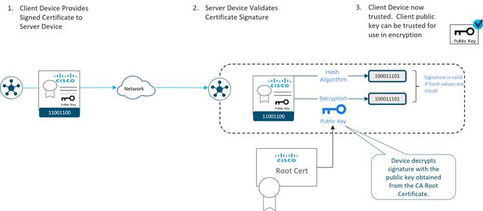
How device certificate validation works:
● The client device presents a CA-signed device certificate to the server.
● The server validates the certificate signature by
1. Running a hash algorithm on the certificate data to get a value, and
2. Decrypting the certificate signature with the public key obtained from the CA Root certificate to get a second value
If both values are equal, then the signature is valid.
● The client device is now trusted and the client public key can be trusted for use in encryption.
 Note that the corresponding root certificate is required in order to validate device certificates.
Control Component Identity
Control Component identity is provided by a Symantec/Digicert or Cisco-signed certificate, or alternatively, an Enterprise CA certificate. Each control component in the network must have a certificate signed and installed. In addition, the root certificate chain for the corresponding CA must also be installed for each control component before the control component certificates can be installed. Additional root chains are installed in order to validate the device certificate of other SD-WAN control components and software devices. Some root certificate chains are pre-loaded or automatically installed, and others, like the Enterprise root CA, must be installed by an administrator.
| Tech tip |
| As of March 31, 2023, Cisco is no longer sponsoring Symantec/Digicert control component X.509 certificates for Cisco Catalyst SD-WAN, so these certificates are no longer being signed and released by Cisco. Symantec/Digicert certificates can still be used if purchased directly from Digicert, then installed manually using the Enterprise CA method on SD-WAN Manager versions 20.3.6, 20.6.4, 20.7.1, and higher. See the field notice for additional information. |
WAN Edge Router Identity
Identity for vEdge hardware routers is provided by a device certificate signed by Avnet, generated during the manufacturing process and burned into the Trusted Platform Module (TPM) chip. Also present in the TPM is the Avnet root certificate chain. The Symantec/Digicert and Cisco root certificates are pre-loaded in software for trust for the control components’ certificates. Additional root certificates may either be loaded manually, distributed automatically by the SD-WAN Manager, or installed during the ZTP automatic provisioning process.
Identity for IOS XE SD-WAN hardware routers, with the exception of the ASR 1002-X, is provided by the Secure Unique Device Identifier (SUDI), which is an X.509v3 certificate associated with a key pair that is protected in hardware (Trust Anchor Module, or TAm). Also present in the TAm is the root certificate chain for the SUDI device certificate. The Symantec/Digicert and Cisco root certificates are pre-loaded in software for trust for the control components’ certificates. Additional root certificates may either be loaded manually, distributed automatically by the SD-WAN Manager, or installed during the Plug-and-Play (PnP) automatic provisioning process.
vEdge cloud routers, ISRv routers, Catalyst 8000v, CSR1000v routers, and Cisco ASR 1002-X routers do not have device certificates pre-installed. Each device uses a One Time Password (OTP)/Token that is generated by the SD-WAN Manager and configured during device deployment for the purpose of a temporary identity. Once the device is temporarily authenticated, a permanent identity is provided by the SD-WAN Manager, which can operate as a Certificate Authority (CA) to generate and install certificates for these devices.
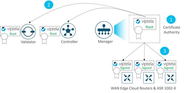
The figure below shows:
1. The SD-WAN Manager acting as a Certificate Authority (CA) for WAN Edge cloud routers and the ASR 1002-X.
2. The SD-WAN Manager distributes the Viptela root certificate to the SD-WAN Validator and SD-WAN Controller in order for them to validate the WAN Edge cloud identity.
3. Once the WAN Edge routers are authenticated via OTP, the SD-WAN Manager CA issues them Viptela-signed certificates that are used from then on for authentication.
Note that if there is an SD-WAN Manager cluster, each SD-WAN Manager signs a certificate for the device and distributes the corresponding root certificate.
Certificates
The following diagram illustrates the device certificates and a subset of root certificates installed for the control components and IOS XE SD-WAN routers. In this example, Cisco PKI certificates are installed on the control components.
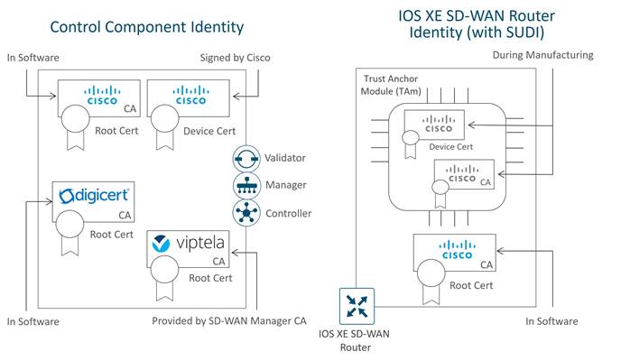
In this example, a Cisco device certificate is installed for control component identity, a Cisco root certificate chain is used to trust other control component certificates, and the Viptela root certificate chain is used to trust cloud router and IOS XE SD-WAN router (with no SUDI) certificates. For the IOS XE-WAN router, a Cisco device certificate is loaded in hardware during manufacturing, and a Cisco root certificate chain is present in software in order to trust control component certificates.
Note that the certificates installed on the control components and the certificates installed in the TAm are both issued by Cisco but they do not share the same CA root chain and thus their CA root chains cannot be used to verify or trust the other.
Authentication/Authorization of SD-WAN Devices
When the control components authenticate each other, they generally:
1. Receive from the opposite control component a trusted device certificate.
2. Compare the certificate serial numbers against the authorized serial number list distributed from the SD-WAN Manager (except when authenticating against the Validator).
3. Compare the organization name of the received certificate OU against the locally configured one (except when authenticating against WAN Edge hardware devices).
4. Validate the trust for the certificate root Certificate Authority (CA)
When WAN Edge devices authenticate to the control components, the WAN Edge routers generally:
1. Receive from the control component a trusted device certificate.
2. Compare the organization name of the received certificate OU against the locally configured one.
3. Validate the trust for the certificate root Certificate Authority (CA).
When control components authenticate to WAN Edge devices, the control components:
1. Send a 256-bit random value to the WAN Edge router, which is signed by the WAN Edge router with a private key.
2. Receive from the WAN Edge the serial and chassis number, the 256-bit value signed with the WAN Edge’s private key, and the trusted board ID certificate (which also includes its CA root certificate chain).
3. Compare the certificate serial numbers against the authorized serial number list distributed from the SD-WAN Manager.
4. Verify the 256-bit value using the public key which is extracted from the board ID certificate.
5. Validate the trust for the certificate root Certificate Authority (CA).
After authentication and authorization succeeds, a DTLS/TLS connection is established.
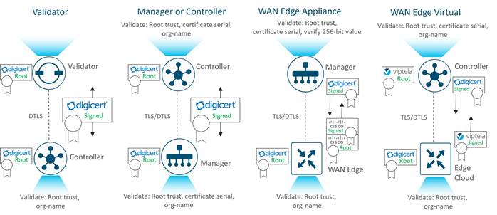
The following diagrams illustrate how different devices authenticate with each other using Symantec/Digicert or Cisco certificates. Enterprise CA certificates operate in the same manner. Note that typically:
● Control components and WAN Edge devices act as clients to initiate connections with the Validator, which acts as a server
● SD-WAN Managers act as clients to initiate connections with the Controller, which acts as a server
● SD-WAN Controllers act as clients to initiate connections with other SD-WAN Controllers and the one with the highest public IP address acts as a server
● WAN Edge devices act as clients to initiate connections with SD-WAN Managers and SD-WAN Controllers, which act as servers
For information on deploying certificates for the Cisco Catalyst SD-WAN solution, refer to the Cisco Catalyst SD-WAN Controller Certificates and Authorized Serial Number File Deployment Guide at https://www.cisco.com/c/en/us/td/docs/solutions/CVD/SDWAN/cisco-sdwan-controller-cert-deploy-guide.html.
Bringing the WAN Edge into the Overlay
In order to join the overlay network, a WAN Edge router needs to establish a secure connection to the SD-WAN Manager so that it can receive a configuration file, and it needs to establish a secure connection with the SD-WAN Controller so that it can participate in the overlay network. The discovery of the SD-WAN Manager and Controller happens automatically and is accomplished by first establishing a secure connection to the SD-WAN Validator.
The following figure shows the sequence of events that occurs when bringing the WAN Edge router into the overlay.
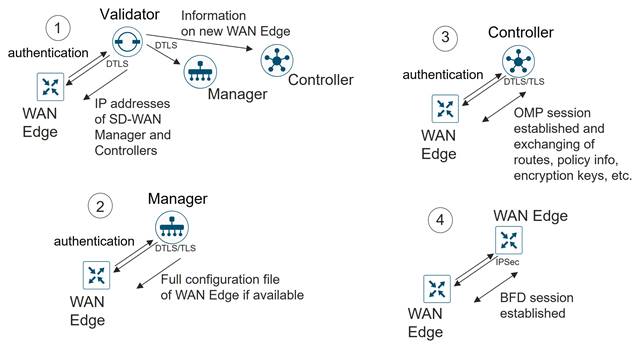
1. Through a minimal bootstrap configuration or through the automated provisioning (ZTP or PnP) process, the WAN Edge router first attempts to authenticate with the SD-WAN Validator through an encrypted DTLS connection. Once authenticated, the SD-WAN Validator sends the WAN Edge router the IP addresses of the SD-WAN Manager network management system (NMS) and the SD-WAN Controllers. The SD-WAN Validator also informs the SD-WAN Controllers and Manager of the new WAN Edge router wanting to join the domain.
2. The WAN Edge router begins establishing secure DTLS or TLS sessions with the SD-WAN Manager and Controllers and tears down the session with the SD-WAN Validator. Once the WAN Edge router authenticates with the SD-WAN Manager NMS, the SD-WAN Manager pushes the configuration to the WAN Edge router if available.
3. The WAN Edge router attempts to establish DTLS/TLS connections to the SD-WAN Controllers over each transport link. When it authenticates to an SD-WAN Controller, it establishes an OMP session and then learns the routes, including prefixes, TLOCs, and service routes, encryption keys, and policies.
4. The WAN Edge router attempts to establish BFD sessions to remote TLOCs over each transport using IPsec.
Onboarding the WAN Edge Router
There are multiple ways to get a WAN Edge router up and running on the network. One way is the manual method, where you can establish a console to the device and configure a few configuration lines, or by using an automated provisioning method, like Zero-Touch Provision (ZTP) or Plug-and-Play (PnP), where you can plug the WAN Edge router into the network and power it on and it will be provisioned automatically. Additionally, there is an option to use the bootstrap method, which applies to IOS XE SD-WAN routers only, where there is a configuration loaded via bootflash or a USB key in order to get the device onto the SD-WAN network which can be used when requirements for automated provisioning are not met. Onboarding virtual cloud routers involves configuring a one-time password (OTP) to get temporarily authenticated before device certificates can be permanently obtained through the SD-WAN Manager. The manual and automated method are briefly described below. For more detailed information on onboarding devices, refer to the Cisco SD-WAN: WAN Edge Onboarding Prescriptive Deployment Guide.
Manual
With the manual configuration method, the idea is to configure the minimum network connectivity and the minimum identifying information along with the SD-WAN Validator IP address or hostname. The WAN Edge router attempts to connect to the SD-WAN Validator and discover the other network control components from there. In order for you to bring up the WAN Edge router successfully, there are a few things that need to be configured on the WAN Edge router:
● Configure an IP address and gateway address on an interface connected to the transport network, or alternatively, configure Dynamic Host Configuration Protocol (DHCP) in order to obtain an IP address and gateway address dynamically. The WAN Edge should be able to reach the SD-WAN Validator through the network.
● Configure the SD-WAN Validator IP address or hostname. If you configure a hostname, the WAN Edge router needs to be able to resolve it. You do this by configuring a valid DNS server address or static hostname IP address mapping under VPN 0.
● Configure the organization name, system IP address, and site ID. Optionally, configure the host name.
| Tech tip |
| In addition to the above requirements, the WAN Edge router needs to have a valid certificate installed, but certificates are already installed on most hardware-based WAN Edge routers at the factory. The system clock also should reflect accurate time because of the certificate authentication and can be set manually or through Network Time Protocol (NTP) if need be, but rarely does this need to be addressed when onboarding new devices. |
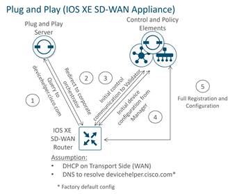
Automated Device Provisioning (ZTP or PnP)
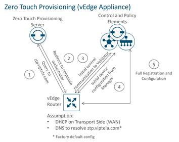
Automated device provisioning for vEdge devices is called Zero-Touch Provisioning (ZTP), and for IOS XE SD-WAN devices, it is called Plug-and-Play (PnP). The processes are very similar, but two different services are involved. Both services are available as a cloud-based service, reachable through the Internet, although an on-premises service can also be deployed.
The automated provisioning procedure starts when the WAN Edge router is powered up for the first time. The vEdge router attempts to connect to a ZTP server with the hostname ztp.viptela.com, where it gets its SD-WAN Validator information. For IOS XE SD-WAN routers, it attempts to connect to the PnP server using the hostname devicehelper.cisco.com. Once the SD-WAN Validator information is obtained, it can then subsequently make connections to the SD-WAN Manager and Controllers in order to get its full configuration and join the overlay network.
 There are a few requirements for automated device provisioning:
● With the hardware vEdge appliances, only certain ports are pre-configured by default to be a DHCP client interface and can be used for ZTP. The following table outlines the ports that must be plugged into the network for ZTP to work. With IOS XE SD-WAN devices, PnP is supported on all routed Gigabit Ethernet interfaces with the exception of the management interface (GigabitEthernet0).
Table 1. vEdge ZTP interfaces
| vEdge model |
Interface |
| vEdge 5000 |
ge0/0 (for network modules in slot 0) |
| vEdge 2000 |
ge2/0 |
| vEdge 1000, ISR1100-4G/8G |
ge0/0 |
| vEdge 100b/m |
ge0/4 |
| vEdge 100wm |
ge0/4, cellular0 |
| ISR1100-4GLTE |
ge0/4, cellular0 |
● The WAN Edge router should be able to get an IP address through DHCP or use Auto IP to discover an IP address.
● The gateway router for the WAN Edge router in the network should have reachability to public DNS servers and be able to reach ztp.viptela.com for vEdge devices and devicehelper.cisco.com for IOS XE SD-WAN devices on the Internet. Alternatively, an on-premises ZTP server can be set up to assist with the onboarding of vEdge and IOS XE SD-WAN routers.
● The SD-WAN device needs to be correctly entered in the PnP portal at https://software.cisco.com and associated with a controller profile defining the SD-WAN Validator hostname or IP address information.
● In the SD-WAN Manager, there must be a device configuration template for the WAN Edge router attached to the WAN Edge device. The system IP and site ID need to be included in this device template in order for the process to work. The ZTP or PnP process cannot succeed without this.
This section reviews how the Cisco Catalyst SD-WAN data plane is established and focuses on the components that help enable that.
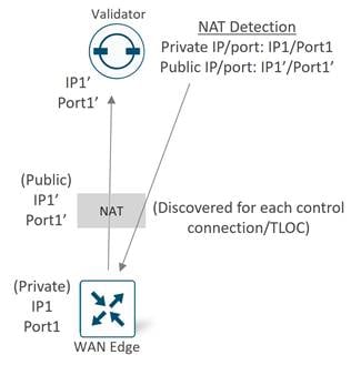
SD-WAN Validator as a NAT Traversal Facilitator
Any SD-WAN control component or SD-WAN router may be unknowingly sitting behind a NAT device. Knowing what IP address/port to connect to from outside the network is crucial to successfully establishing control and data plane connections in the SD-WAN network. The SD-WAN Validator plays a crucial role and acts as a Session Traversal Utilities for NAT (STUN) server, which allows other control components and SD-WAN routers to discover their own mapped/translated IP addresses and port numbers. SD-WAN devices advertise this information along with their TLOCs so other SD-WAN devices have information in order to make successful connections.
Data Plane Privacy and Encryption
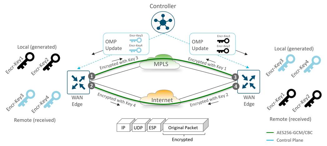
WAN Edge routers secure data traffic exchanged between them using IPsec with encryption keys which encrypt and decrypt data. In traditional IPsec environments, Internet Key Exchange (IKE) is used to facilitate the key exchange between peers. This creates per-pair keys, requiring each device to manage n^2 key exchanges and (n-1) different keys in a full-meshed environment. For more efficient scaling in the Cisco Catalyst SD-WAN network, no IKE is implemented since identity has already been established between the WAN Edge routers and the control components. The control plane, which is already authenticated, encrypted, and tamperproof using DTLS or TLS, is used to communicate AES-256 symmetric keys. Each WAN Edge router generates one AES key per TLOC and transmits this information to the SD-WAN Controller in OMP route packets, which is then distributed to all WAN Edge routers.
Each key lifetime is 24 hours by default. A new key is generated every 12 hours, sent to the SD-WAN Controllers and is then distributed to the other WAN Edge routers, which means two keys are present at any one time. While WAN Edge routers switch to using the newly generated key, the last known key is still held for another 12 hours and traffic is accepted using either key. If the OMP sessions are lost to the SD-WAN Controllers, the WAN Edge routers keep using the last information they have (configuration, policies, routes, and IPsec keys) for up to 12 hours, which is the length of the OMP graceful restart timer. The two keys ensure that the 12 hour OMP graceful restart timer can be supported, because there’s no way to know when an OMP outage could occur.
| Tech tip |
| Pair-wise keys can be alternatively configured starting in 19.2 vEdge and 16.12.1b IOS XE SD-WAN code. Pair-wise keys still make use of the AES256 symmetric encryption algorithm, but instead of an SD-WAN router sharing the same TLOC key with all other SD-WAN routers in the overlay, this method shares a unique TLOC key with each SD-WAN router that it shares a path with. |
For encrypting data plane traffic, a modified version of Encapsulating Security Payload (ESP) is used to protect the data packet payload. The encryption algorithm is AES-256 GCM but can fall back to AES-256 CBC if needed (as in the case of multicast traffic). The authentication algorithm, which verifies the integrity and authenticity of data, is configurable and is included in TLOC properties which is exchanged with the SD-WAN Controllers. By default, AH-SHA1 HMAC and ESP HMAC-SHA1 are both configured. When multiple authentication types are configured, the strongest method between the two points is chosen (AH-SHA1 HMAC).
Anti-Replay
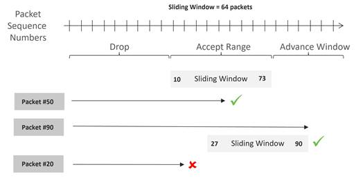
With anti-replay protection, IPsec packets are protected from attackers injecting or making changes to packets. The sender assigns sequence numbers to the IPsec packets, which increase sequentially. The destination checks these sequence numbers and maintains a sliding window of sequence numbers that it will accept, since packets may not always arrive in order. Packets with duplicate sequence numbers are dropped. Packets that arrive to the left of the sliding window are considered old and the destination drops them. For packets that arrive to the right of the sliding window, the packets are verified and the sliding window is advanced for the packet sequence number with the highest value.
Anti-replay cannot be disabled, and by default, the sliding window is set to 512 packets. It must be a power of 2 and can be set between 64 and 4096 with the replay-window command. In certain network scenarios, such as with QoS coupled with large amounts of higher priority traffic, 512 packets may not be a large enough window size, so anti-replay may drop too many legitimate packets. It’s recommended to set this window size to the maximum of 4096.
The figure below illustrates the anti-replay feature. Packets arriving with sequence numbers in the sliding window are accepted, packets arriving to the right of the window are accepted and advance the sliding window, and packets arriving to the left of the sliding window are discarded.
Multiple Sequence Number Spaces (multi-SNS)
Due to QoS queuing happening after encryption, there is a chance for anti-replay drops to occur as non-priority packets are queued and delayed and, thus, they may miss their replay window. While maximizing the anti-replay window can help, it may not eliminate the problem in all circumstances.
SD-WAN mitigates this with multiple sequence number spaces (multi-SNS) implemented on IOS XE SD-WAN routers. Multi-SNS maintains multiple unique sequence number spaces per security association. The spaces align with the egress queuing scheme so that all packets in a given queue receives a sequence number from the same sequence number space. This eliminates the possibility of egress QoS causing reordering of packets since packets in the same sequence number space go through the same queue.
Multi-SNS is always enabled for SD-WAN overlay tunnels, regardless of whether QoS is configured or not. By default, two spaces are used, one for BFD traffic (queue 0) and one for data traffic (queue 2). When QoS is configured, it will automatically create unique sequence number spaces for each class defined, up to eight for the IOS XE SD-WAN router. Each QoS class has its SNS group encoded into the 32-bit SPI field in the ESP/AH header.
It is important that both sides of the IPsec tunnel have QoS configured with a similar number of classes, otherwise, anti-replay could indiscriminately drop packets.
For additional details on data plane security and other security topics , see https://www.cisco.com/c/en/us/td/docs/routers/sdwan/configuration/security/vedge/security-book/security-overview.html.
Transport Locators (TLOCs)
Transport Locators, or TLOCs, are the attachment points where a WAN Edge router connects to the WAN transport network. A TLOC is uniquely identified and represented by a three-tuple, consisting of system IP address, color, and encapsulation (Generic Routing Encapsulation [GRE] or IPsec). TLOC routes are advertised to the SD-WAN Controllers via OMP, along with a number of attributes, including the private and public IP address and port numbers associated with each TLOC, as well as color and encryption keys. These TLOC routes with their attributes are distributed to other WAN Edge routers. Now with the TLOC attributes and encryption key information known, the WAN Edge routers can attempt to form BFD sessions using IPsec with other WAN Edge routers.
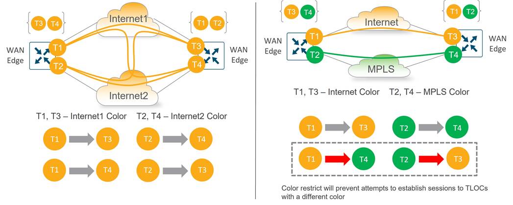
By default, WAN Edge routers attempt to connect to every TLOC over each WAN transport, including TLOCs that belong to other transports marked with different colors. This is helpful when you have different Internet transports at different locations, for example, that should communicate directly with each other. To prevent this behavior, there is a restrict keyword that can be specified along with the color of the tunnel. This prevents attempts to establish BFD sessions to TLOCs with different color. This is commonly used on private transports to prevent forming sessions with public transports.
The following figure illustrates how the restrict keyword affects BFD session establishment. In the left diagram, the restrict keyword is not used so all TLOCs can establish sessions to each other. In the right diagram, the restrict keyword is used on the MPLS color, resulting in MPLS TLOCs only being able to form sessions with other MPLS TLOCs.
Color
Colors are abstractions used to identify individual WAN transports that terminate on WAN Edge devices. Colors are statically defined keywords (not free-form labels), and colors are significant because they identify an individual transport as either public or private. The colors metro-ethernet, mpls, and private1, private2, private3, private4, private5, and private6 are considered private colors. They are intended to be used for private networks or in places where you will have no NAT addressing of the transport IP endpoints. The public colors are 3g, biz-internet, blue, bronze, custom1, custom2, custom3, default, gold, green, lte, public-internet, red, and silver. They are intended to be used for public networks or in places where you will use public IP addressing of the transport IP endpoints, either natively or through NAT. Color dictates the use of either private IP or public IP address when communicating through the control or data plane.
| Tech tip |
| On WAN Edge routers, every TLOC is associated to a private IP address: public IP address pair. The private IP address is the IP address assigned to the interface of the SD-WAN device. This is the pre-NAT address, and despite the name, can be a publicly routable address or a private (RFC 1918). The public IP address is the Post-NAT address detected by the SD-WAN Validator. This address can be either a publicly routable address or a private (RFC 1918) address. In the absence of NAT, the private and public IP address of the SD-WAN device are the same. |
Communication Between Private and Public Colors
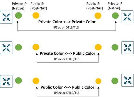
When an SD-WAN device contacts and authenticates to the SD-WAN Validator, the Validator will learn both the peer private IP address/port number and the peer public address/port number settings of the SD-WAN device during the exchange. The private IP address refers to the native IP address assigned to the interface and the public IP address refers to the post-NAT IP address, if NAT is involved.
When two SD-WAN devices attempt to communicate with each other, both using interfaces with private colors, each side will attempt to connect to the remote device’s private IP address. If one or both sides are using public colors, then each side will attempt to connect to the remote device’s public IP address.
| Tech tip |
| Note that when the site IDs are the same but the colors are public, the private IP address will instead be used for communication. This can occur for WAN Edge routers attempting to communicate to an SD-WAN Manager or SD-WAN Controller located on-premise on the same site or between on-premise controllers located behind the same firewall, as examples. |
The following diagram demonstrates the general behavior. These rules apply to:
● WAN Edge routers using IPsec to other WAN Edge routers
● DTLS/TLS connections between WAN Edge routers and SD-WAN Managers and Controllers
● DTLS/TLS connections between SD-WAN Managers and SD-WAN Controllers
Carrier Setting
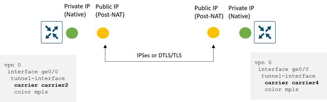
If you are using a private color and need NAT to communicate to another private color, the carrier setting in the configuration dictates whether you use the private or public IP address. Using this setting, two private colors can establish a session when one or both are using NAT. If the carrier setting is the same between the interfaces, the private IP address is used between them, and if the carrier setting is different, then the public IP address is used. The diagram below demonstrates this.
Public and Private IP address example
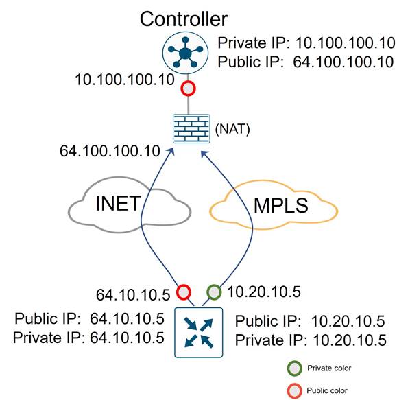
The following example illustrates the use of public and private IP addresses with colors in a network. The following diagram shows an SD-WAN Controller interface addressed with a private (RFC 1918) IP address, but a firewall translates that address into a publicly routable IP address that WAN Edge routers use to reach it. It also shows a WAN Edge router with an MPLS interface configured with an RFC 1918 IP address and an Internet interface configured with a publicly routable IP address. Since there is no NAT translating the private IP addresses of the WAN Edge router, the public and private IP addresses in both cases are the same.
The transport color on the SD_WAN Controller is set to a public color and on the WAN Edge, the Internet side is set to a public color and the MPLS side is set to a private color. The WAN Edge router reaches the Controller on either transport using the remote public IP address (64.100.100.10) as the destination due to the public color on the SD-WAN Controller interface.
Bidirectional Forwarding Detection (BFD)
On Cisco WAN Edge routers, BFD is automatically started between peers and cannot be disabled. It runs between all WAN Edge routers in the topology encapsulated in the IPsec tunnels and across all transports. BFD operates in echo mode, which means when BFD packets are sent by a WAN Edge router, the receiving WAN Edge router returns them without processing them. Its purpose is to detect path liveliness and it can also perform quality measurements for application-aware routing, like loss, latency, and jitter. BFD is used to detect both black-out and brown-out scenarios.
Tunnel Liveliness
To detect whether an IPsec tunnel is up, BFD hello packets are sent every 1000 milliseconds/1 second by default on every tunnel interface. The default BFD multiplier is 7, which means the tunnel is declared down after 7 consecutive hellos are lost. The BFD hello interval and multiplier are configurable on a per color basis.
BFD packets are marked with DSCP 48, which is equivalent to CS6 or IP Precedence 6. Packets are placed in the low latency, high priority QoS queue (LLQ) before being transmitted on the wire but are not subjected to the LLQ policer. Though rarely needed, the DSCP value can be modified using an egress ACL on the WAN interface.
| Tech tip |
| The Per-Class Application-Aware Routing feature is introduced in SD-WAN Manager version 20.4.1 and IOS XE SD-WAN version 17.4.1a. BFD probes can now be assigned per class with the same DSCP value that is assigned to traffic in that class, so the probes take a similar path through the provider network (including the QoS policies). |
Path Quality
BFD is used not only to detect blackout conditions but is also used to measure various path characteristics such as loss, latency, and jitter. These measurements are compared against the configured thresholds defined by the application-aware routing policy, and dynamic path decisions can be made based on the results in order to provide optimal quality for business-critical applications.
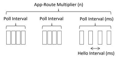
For measurements, the WAN Edge router collects packet loss, latency, and jitter information for every BFD hello packet. This information is collected over the poll-interval period, which is 10 minutes by default, and then the average of each statistic is calculated over this poll-interval time. A multiplier is then used to specify how many poll-interval averages should be reviewed against the SLA criteria. By default, the multiplier is 6, so 6 x 10-minute poll-interval averages for loss, latency, and jitter are reviewed and compared against the SLA thresholds before an out-of-threshold decision is made. The calculations are rolling, meaning, on the seventh poll interval, the earliest polling data is discarded to accommodate the latest information, and another comparison is made against the SLA criteria with the newest data.
Since statistical averages are used to compare against configured SLA criteria, how quickly convergence happens depends on how far out of threshold a parameter is. Using default settings, the best case is an out-of-threshold condition that occurs after 1 poll interval is completed (10 minutes) and in the worst case, it occurs after 6 poll intervals are completed (60 minutes). When an out-of-threshold condition occurs, traffic is moved to a more optimal path.
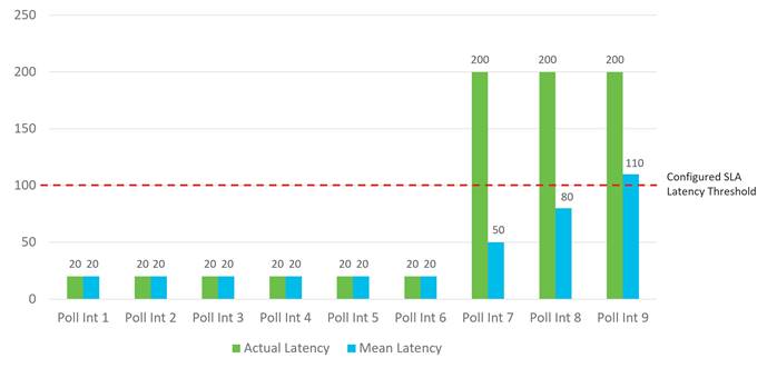
The following figure shows an example when an out-of-threshold condition is recognized when latency suddenly increases. When latency jumps from 20 ms to 200 ms at the beginning of poll-interval 7, it takes 3 poll intervals of calculations before the latency average over 6 poll intervals crosses the configured SLA threshold of 100 ms.
You may want to adjust application route poll-interval values, but you need to exercise caution, since settings that are too low can result in false positives with loss, latency, and jitter values, and can result in traffic instability. It is important that there is a sufficient number of BFD hellos per poll interval for the average calculation, or large loss percentages may be incorrectly tabulated when one BFD hello is lost. In addition, lowering these timers can affect overall scale and performance of the WAN Edge router.
For 1 second hellos, the lowest application route poll-interval that should be deployed is 120 seconds. With 6 intervals, this gives a 2-minute best case and 12-minute worst case before an out-of-threshold is declared and traffic is moved from the current path. Any further timer adjustments should be thoroughly tested and used cautiously.
NAT
NAT types used at branch sites need to be carefully considered in your SD-WAN design, because it can affect whether sites can form connections and communicate directly with each other.
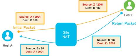
All NAT types can create mappings for source IP address, source port, destination IP, and destination port in an IP network packet. In the following common example, source NAT is used to change the source private (RFC 1918) IP address A of a packet to a publicly routable source IP address Z so the host can get connectivity to an Internet-based server (Host B). When the response packet is returned from the Internet, the destination IP address Z is mapped back to the original IP address A and then delivered to the originating host.
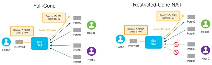
There are four different types of NAT with different behaviors to consider:
● Full-Cone NAT: This NAT type is also called one-to-one NAT and is the least restrictive NAT type. This maps one local IP address and port to one public IP address and port. Once a NAT translation occurs or a static one-to-one NAT is configured for a local IP address and port, any external host sourced from any port can send data to the local host through the mapped NAT IP address and port.
● Restricted-Cone NAT: This NAT is similar to Full-Cone NAT but is more restrictive. Once an internal host A sends a packet to an external host B and a NAT translation occurs for the local IP address and port, only the external host B (sourced from any port) can send data to the local host A through the mapped NAT IP address and port.
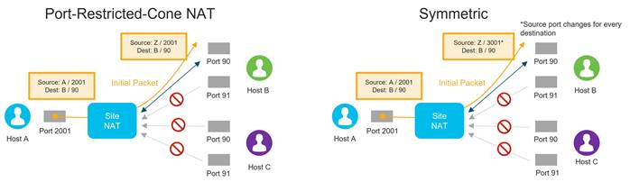
● Port-Restricted-Cone NAT: This NAT is similar to Restricted-Cone NAT, but the restriction includes port numbers. Once an internal host A sends a packet to an external host B and port number X and a NAT translation occurs for the local IP address and port, only the external host B (sourced only from port X) can send data to the local host A through the mapped NAT IP address and port.
● Symmetric NAT: This is the most restrictive NAT and is similar to Port-Restricted-Cone NAT, where only the external host B (sourced only from port X) can send data to the local host A through the mapped NAT IP address and port. Symmetric NAT differs in that a unique source port is used every time host A wants to communicate with a different destination. Symmetric NAT can cause issues with STUN servers because the IP address/port mapping the STUN server learns is a different mapping to another host.
NAT Recommendations
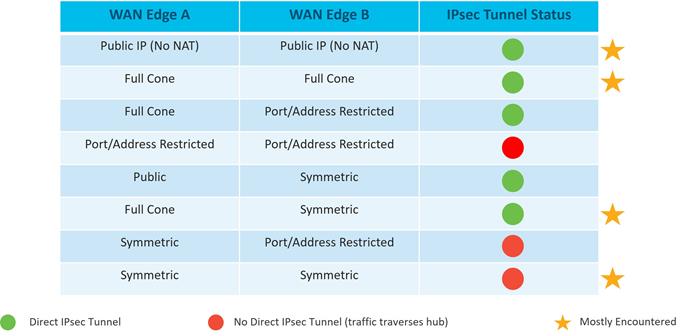
Though several types of NAT are supported with WAN Edge routers, if full mesh traffic is desired, take care to ensure at least one side of the WAN Edge tunnel can always initiate a connection inbound to a second WAN Edge even if there is a firewall in the path. It is recommended to configure full-cone, or 1-to-1 NAT at the data center or hub site so that, regardless of what NAT type is running at the branch (restricted-cone, port-restricted cone, or symmetric NAT), the branch can send traffic into the hub site using IPsec at a minimum without issue. Two sites with firewalls running symmetric NAT will have issues forming a tunnel connection, as this NAT translates the source port of each side to a random port number, and traffic cannot be initiated from the outside. Symmetric NAT configured at one site requires full-cone NAT or a public IP with no NAT on the other site in order to establish a direct IPsec tunnel between them. Sites which cannot connect directly should be set up to reach each other through the data center or other centralized site.
| Tech tip |
| There are cases when a WAN Edge router may be deployed behind a NAT device using symmetric NAT. If a WAN Edge router goes out of equilibrium (when it is no longer connected to the proper number of control components through DTLS/TLS or OMP sessions), it attempts to establish a permanent connection back to the Validator on the TLOC. Due to symmetric NAT, a new public source port number is discovered for the WAN Edge, so the WAN Edge source port number changes for all its control and data plane connections. This causes BFD to re-establish. In cases where there are more than 2 vBonds in the network, continuous source port changes with BFD flapping can take place. This issue is fixed in 20.9.5/17.9.5, 20.12.3/17.12.3, 20.14/17.14 and above. |
The following table shows different NAT type combinations and the corresponding IPsec tunnel status:
| Tech tip |
| Note that for GRE-encapsulated tunnels behind NAT, only one-to-one NAT is supported. Any type of NAT with port overloading is not supported since GRE packets lack an L4 header. |
Underlay vs Overlay Routing
The Cisco Catalyst SD-WAN network is divided into the two distinct parts: the underlay and overlay network. The underlay network is the physical network infrastructure which connects network devices such as routers and switches together and routes traffic between devices using traditional routing mechanisms. In the SD-WAN network, this is typically made up of the connections from the WAN Edge router to the transport network and the transport network itself. The network ports that connect to the underlay network are part of VPN 0, the transport VPN. Getting connectivity to the Service Provider gateway in the transport network usually involves configuring a static default gateway (most common), or by configuring a dynamic routing protocol, such as BGP or OSPF. These routing processes for the underlay network are confined to VPN 0 and their primary purpose is for reachability to TLOCs on other WAN Edge routers so that IPsec tunnels can be built to form the overlay network.
The IPsec tunnels which traverse from site-to-site using the underlay network help to form the SD-WAN overlay network. The Overlay Management Protocol (OMP), a TCP-based protocol similar to BGP, provides the routing for the overlay network. The protocol runs between SD-WAN Controllers and WAN Edge routers where control plane information is exchanged over secure DTLS or TLS connections. The SD-WAN Controller acts a lot like a route reflector; it receives routes from WAN Edge routers, processes and applies any policy to them, and then advertises the routes to other WAN Edge routers in the overlay network.
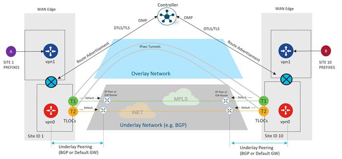
OMP Overview
OMP runs between WAN Edge routers the SD-WAN Controllers and also as a full mesh the SD-WAN Controllers. When DTLS/TLS control connections are formed, OMP is automatically enabled. OMP peering is established using the system IPs and only one peering session is established between a WAN Edge device and an SD-WAN Controller even if multiple DTLS/TLS connections exist. OMP exchanges route prefixes, next-hop routes, crypto keys, and policy information.
OMP advertises three types of routes from WAN Routers to the SD-WAN Controllers:
● OMP routes, or vRoutes, are prefixes that are learned from the local site, or service side, of a WAN Edge router. The prefixes are originated as static or connected routes, or from within the OSPF, BGP, or EIGRP protocol, and redistributed into OMP so they can be carried across the overlay. OMP routes advertise attributes such as transport location (TLOC) information, which is similar to a BGP next-hop IP address for the route, and other attributes such as origin, origin metric, originator, preference, site ID, tag, and VPN. An OMP route is only installed in the forwarding table if the TLOC to which it points is active.
● TLOC routes advertise TLOCs connected to the WAN transports, along with an additional set of attributes such as TLOC private and public IP addresses, carrier, preference, site ID, tag, weight, and encryption key information.
● Service routes represent services (firewall, IPS, application optimization, etc.) that are connected to the WAN Edge local-site network and are available for other sites for use with service insertion. In addition, these routes include originator System IP, TLOC, and VPN-IDs; the VPN labels are sent in this update type to tell the SD-WAN Controllers what VPNs are serviced at a remote site.
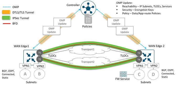
By default, OMP only advertises the best route or routes in the case of equal-cost paths. It is recommended that send-backup-paths OMP parameter is enabled on the SD-WAN Controller, so OMP advertises additional valid paths that don’t qualify as the best paths for a given prefix. In addition to improving convergence, this allows the WAN Edge router to make the best path decision which may also be based on TLOC availability.
In addition, OMP advertises only four equal-cost paths for any particular prefix. This may not be enough in some designs, as this limit is easily reached with a site that uses dual WAN Edge routers, each connected to two different transports. The recommendation is to set the SD-WAN Controller send-path-limit OMP parameter, or the Number of Paths Advertised per Prefix, to the maximum of 16. The send-path-limit parameter includes both best paths and backup paths. Note that the WAN Edge router installs only four equal-cost paths by default. If you want to increase this value, use the ecmp-limit OMP parameter on the WAN Edge router to change it.
Note that by default, the connected, static and OSPF (intra-area and inter-area) route types are automatically distributed from service-side VPNs into OMP. All other route types (including OSPF external routes) need to be explicitly configured. OMP routes are assigned an admin distance of 250 for vEdge routers, and 251 for IOS XE SD-WAN routers, so the routes at the local site take precedence.
| Tech tip |
| It is recommended to set the OMP hold timer to 300 seconds for overlays with more than 500 devices in order to improve resiliency. The setting can be found in the OMP feature profile or feature template or under the sdwan>omp>timers CLI configuration. OMP can affect convergence for VRRP if tracking is used, so ensure you are tracking on prefix and not on OMP. The default OMP hold time is changed from 60 seconds to 300 seconds starting with the 20.12 SD-WAN Manager software version. |
See Unicast Overlay Routing Overview for additional information on OMP routing and path selection.
Graceful Restart
If an OMP peer becomes unavailable, OMP graceful restart allows other OMP peers to continue operating temporarily. When a WAN Edge router loses connection to the SD-WAN Controllers, the router can continue forwarding traffic using last known good routing information. The default OMP graceful restart value is 12 hours and can be set to a maximum of 604,800 seconds, which is equivalent to 7 days. The IPsec rekey timer is set to 24 hours by default, and although both timers are configurable, the IPsec rekey timer must be at least two times the value of the OMP graceful restart timer. This is because the SD-WAN Controllers distribute the IPsec keys to the WAN Edge routers, and if connections to the SD-WAN Controllers are lost, any IPsec rekeying that occurs within the graceful restart time would cause traffic loss.
The secure sessions between the WAN Edge routers and the controllers (and between controllers), by default are DTLS, which is User Datagram Protocol (UDP)-based. The default base source port is 12346. The WAN Edge may use port hopping where the devices try different source ports when trying to establish connections to each other in case the connection attempt on the first port fails. The WAN Edge will increment the port by 20 and try ports 12366, 12386, 12406, and 12426 before returning to 12346. Port hopping is configured by default on a WAN Edge router, but you can disable it globally or on a per-tunnel-interface basis. Note that port hopping is disabled on the controllers by default and should be kept disabled. Control connections on the SD-WAN Manager and the SD-WAN Controller with multiple cores have a different base port for each core.
| Tech tip |
| It is recommended to disable port-hopping on SD-WAN routers in the data center, regional hub, or any place where aggregate traffic exists because BFD and data connections can be disrupted if port hopping occurs. It is also recommended to disable it on TLOCs configured with private colors at the branches, since control traffic on private colors may use another site to reach the SD-WAN control components, and any control connection disruption can cause port-hopping and impact BFD as well. |
For WAN Edge routers that sit behind the same NAT device and share a public IP address, you do not want each WAN Edge to attempt to connect to the same controller using the same port number. Although NAT or port hopping may allow both devices to use a unique source port, you can instead configure an offset to the base port number of 12346, so the port attempts will be unique (and more deterministic) among the WAN Edge routers. A port offset of 1 will cause the WAN Edge to use the base port of 12347, and then port-hop with ports 12367, 12387, 12407, and 12427. Port offsets need to be explicitly configured, and by default, the port offset is 0.
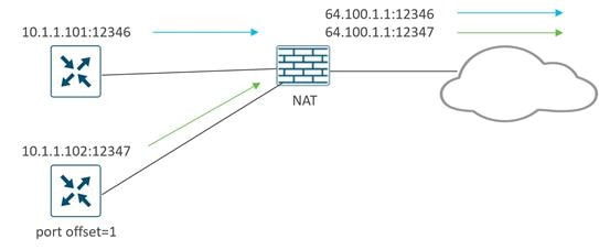
Alternatively, you can use TLS to connect to the SD-WAN Manager and SD-WAN Controllers, which is TCP-based instead of UDP-based. SD-WAN Validator connections always use DTLS, however. TCP ports originate on the WAN Edge from a random port number, and control connections to controllers with multiple cores have a different base port for each core, similar to the DTLS case.
Examples of DTLS and TLS control connections are shown in the following diagram. Note that every core on the SD-WAN Manager and Controller makes a permanent connection to the SD-WAN Validator while WAN Edge routers makes a transient connection to the SD-WAN Validator, using DTLS only. The WAN Edge routers connect to only one SD-WAN Manager and SD-WAN Controller core. The SD-WAN Manager and WAN Edge routers act as clients when connecting to SD-WAN Controllers, so when using TLS, their source ports are random TCP ports > 1024. The WAN Edge router in the TLS example is configured with an offset of 2, so it uses the offset on the DTLS source port when connecting to the SD-WAN Validator.
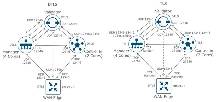
IPsec tunnel encapsulation from a WAN Edge router to another WAN Edge router uses UDP with similar ports as defined by DTLS.
Ensure that any firewalls in the network allow communication between WAN Edge routers and controllers and between controllers. Ensure that they are configured to allow return traffic as well.
| Tech tip |
| It is critical that every core of each Controller and Manager is connected to every Validator through a control connection. Failure to meet this requirement could result in Edge devices experiencing data plane and/or management connectivity issues. |
The following table is a summary of the ports used for control plane and data plane traffic.
Table 2. DTLS, TLS, and IPsec ports for SD-WAN device connections
| Source device |
Source port |
Destination device |
Destination port |
| Manager/Controller (DTLS) |
Core0 = UDP 12346 |
Validator |
UDP 12346 |
| Manager (DTLS) |
UDP 12346 |
Controller |
UDP 12346 |
| Manager (DTLS) |
UDP 12346 |
Manager |
UDP 12346 |
| Controller (DTLS) |
UDP 12346 |
Controller |
UDP 12346 |
| WAN Edge (DTLS) |
UDP 12346+n, 12366+n, 12386+n, 12406+n, and 12426+n, where n=0-19 and represents the configured offset |
Validator |
UDP 12346 |
| WAN Edge (DTLS) |
UDP 12346+n, 12366+n, 12386+n, 12406+n, and 12426+n, where n=0-19 and represents the configured offset |
Manager/Controller |
Core0 = UDP 12346 |
| Manager (TLS) |
TCP random port number > 1024 |
Controller |
TCP 23456 |
| Manager (TLS) |
TCP random port number > 1024 |
Manager |
TCP 23456 |
| Controller (TLS) |
TCP random port number > 1024 |
Controller |
TCP 23456 |
| WAN Edge (TLS) |
TCP random port number > 1024 |
Manager/Controller |
Core0 = TCP 23456 |
| WAN Edge (IPsec) |
UDP 12346+n, 12366+n, 12386+n, 12406+n, and 12426+n, where n=0-19 and represents the configured offset |
WAN Edge |
UDP 12346+n, 12366+n, 12386+n, 12406+n, and 12426+n, where n=0-19 and represents the configured offset |
| Tech tip |
| If a NAT gateway is present in the underlay and performs source port translation without preserving the original port, it may assign a random source port under certain conditions. This can occur when multiple devices are behind the same post-NAT IP address using the same source port, or if the port is already occupied by existing sessions. As a result, the assigned source port may differ from the specified range of UDP ports (12346+n, 12366+n, etc). It is essential to consider this when configuring inbound firewall rules on the remote router sites. |
Ports Behind NAT Overload Interfaces on IOS XE SD-WAN Routers
When using TLOC extension to a public transport, source IP address and ports for control and data connections from a WAN Edge device will typically get subjected to NAT overload from the WAN Edge device interface directly connected to the public transport. The NAT overload port numbers can vary from 5062 to 6200.
| Source Device |
Source Port |
Destination |
| WAN Edge (DTLS/IPsec) behind an IOS XE SD-WAN NAT overload interface |
UDP 5062-6200 |
Any |
Note that for NAT interface (and loopback interface) overload, you can use the ip nat settings preserve-sdwan-ports command in a CLI add-on template to choose SD-WAN known ports instead (starting in Cisco IOS XE SD-WAN Release 17.10.1a).
Additional Ports for the VPN 0 Transport
In VPN 0 on the transport interface, almost all communication occurs over DTLS/TLS or IPsec, but there are a few other ports that need consideration.
Network Configuration Protocol (NETCONF)
The NETCONF protocol defines a mechanism through which network devices are managed and configured. The SD-WAN Manager uses NETCONF for communication with SD-WAN devices, primarily over DTLS/TLS, but there are a few situations where NETCONF is used natively before DTLS/TLS connections are formed:
● When any control component (SD-WAN Manager, Validator, or Controller) is added to the SD-WAN Manager, an SD-WAN Manager instance uses NETCONF to retrieve information from them and allows them to be added as devices into the GUI. This might be when initially adding controllers to the SD-WAN Manager, or for incremental horizontal scaling deployments, by adding SD-WAN Manager instances to a cluster or adding additional SD-WAN Controllers or Validators.
● NETCONF is also used from the SD-WAN Manager when generating Certificate Signing Requests from control components through the SD-WAN Manager GUI before DTLS/TLS connections are formed.
NETCONF is encrypted SSH using AES-256-GCM and uses TCP destination port 830.
Secure Shell (SSH)
SSH provides a secure, encrypted channel over an unsecured network. It’s typically used to log into a remote machine to execute commands, but it can also be used in file transfer (SFTP) and secure copy (SCP) from and to all SD-WAN devices. The SD-WAN Manager uses SCP to install signed certificates onto the controllers if DTLS/TLS connections are not yet formed between them. SSH uses TCP destination port 22.
Network Time Protocol (NTP)
NTP is a protocol used for clock synchronization between network devices. If an NTP server is being used and can natively be accessed through the VPN 0 WAN transport be sure NTP is allowed through the firewall. NTP uses UDP port 123.
Domain Name System (DNS)
DNS may be needed if you are using a DNS server to resolve hostnames and the server is reachable natively through the VPN 0 transport. You may need DNS to resolve the SD-WAN Validator or NTP server name. DNS uses UDP port 53.
Hypertext Transfer Protocol Secure (HTTPS) (SD-WAN Manager)
HTTPS provides an admin user or operator secure access to the SD-WAN Manager, which can be accessed through the VPN 0 interface. The SD-WAN Manager can be accessed using TCP port 443 or 8443.
The SD-WAN Manager reaches several services, such as certificate services and the plug and play portal, using HTTPS (TCP port 443). For Symantec/Digicert certificates, the destination host is certmanager.blu.websecurity.symauth.net and for Cisco PKI certificates, the destination is cloudsso.cisco.com, followed by apx.cisco.com. If syncing to the Cisco Plug and Play portal for automatically downloading the WAN Edge router authorized serial number list, the SD-WAN Manager also needs to reach HTTPS with the destination cloudsso.cisco.com, followed by apx.cisco.com.
Protocols Allowed Through the Tunnel Interface
Note that the VPN 0 transport interface is configured with a tunnel so control and data plane traffic can be encrypted, and native traffic can be restricted. Other than DTLS or TLS, the following native protocols are allowed through the interface by default:
DHCP
DNS
ICMP
HTTPS
| Tech tip |
| Ensure any additional required protocols are also allowed on the tunnel under the transport interface within VPN 0 on the SD-WAN device. Through the SD-WAN Manager GUI, you can enable and disable protocols under the tunnel interface in the VPN Interface feature template. Through CLI, the command is allow-service [protocol] under the tunnel-interface. You may need to consider enabling ntp and dns on all SD-WAN devices. Enable netconf on the controllers if needed for onboarding, then it can be disabled. You should also consider enabling ssh on controllers while you are deploying them for certificate installation purposes. Ensure any firewalls in the network allow this communication as well. After initial onboarding, disable ssh on the transport interface if possible. SSH from the SD-WAN Manager is encrypted and traverses the overlay, so you do not need to permit native SSH on the interface if SD-WAN Manager control connections can be established. If SSH is allowed and someone attempts an SSH session and enters an incorrect login 5 consecutive times, a strict lockout period of 15 minutes is enforced for the user. Any login attempt in that time resets the timers and can trigger an indefinite lockout condition. It is also recommended that a secondary username and password is configured with netadmin privileges. |
These additional ports are summarized as follows:
Table 3. Summary of additional VPN 0 protocols for SD-WAN device communication
| Service |
Protocol/Port |
Direction |
| NETCONF |
TCP 830 |
bidirectional |
| SSH |
TCP 22 |
bidirectional |
| NTP |
UDP 123 |
outgoing |
| DNS |
UDP 53 |
outgoing |
| HTTPS |
TCP 443/8443 |
bidirectional |
Ports for Controller Management
Additional management protocols may be used on the VPN 512 interface of SD-WAN devices. They are summarized as follows:
Table 4. Summary of management protocols for SD-WAN devices
| Service |
Protocol/Port |
Direction |
| NETCONF |
TCP 830 |
bidirectional |
| SSH |
TCP 22 |
incoming |
| SNMP Query |
UDP 161 |
incoming |
| Radius |
UDP 1812 |
outgoing |
| SNMP Trap |
UDP 162 |
outgoing |
| Syslog |
UDP 514 |
outgoing |
| TACACS |
TCP 49 |
outgoing |
| HTTPS (SD-WAN Manager) |
TCP 443, 8443 |
incoming |
Ports for SD-WAN Manager Clustering and Disaster Recovery
For an SD-WAN Manager cluster, the following ports may be used on the cluster interface of the controllers. Ensure the correct ports are opened within firewalls that reside between cluster members.
Table 5. Summary of ports needed for SD-WAN Manager clustering
| SD-WAN Manager Service |
Protocol/Port |
Direction |
| Application Server |
TCP 80, 443, 7600, 8080, 8443, 57600 |
bidirectional |
| Configuration Database |
TCP 5000, 7474, 7687 |
bidirectional |
| Coordination Server |
TCP 2181, 2888, 3888 |
bidirectional |
| Message Bus |
TCP 4222, 6222, 8222 |
bidirectional |
| Statistics Database |
TCP 9200, 9300 |
bidirectional |
| Tracking of device configurations (NCS and NETCONF) |
TCP 830 |
bidirectional |
| Cloud Agent |
TCP 8553 |
bidirectional |
| Cloud Agent V2 |
TCP 50051 |
bidirectional |
| SD-AVC |
TCP 10502, 10503 |
bidirectional |
If disaster recovery is configured, ensure that the following ports are opened over the out-of-band interface across the data centers between the primary and standby cluster:
Table 6. Summary of ports needed for SD-WAN Manager disaster recovery
| Protocol/Port |
Direction |
|
| Disaster Recovery |
TCP 8443, 830 |
bidirectional |
Overview
In any SD-WAN deployment, the control components are deployed and configured first, followed by the main hub or data center sites, and lastly, the remote sites. As each site is deployed, the control plane is established first, automatically followed by the data plane. It is recommended that hub sites are used to route between SD-WAN and non-SD-WAN sites as the sites are being migrated to SD-WAN.
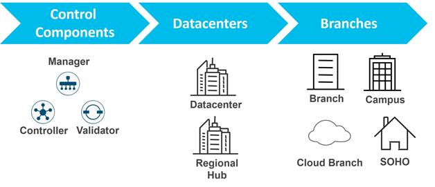
Control Components Deployment Options
There are multiple, flexible control component deployment options available for customers. Control components can be deployed:
● In a Cisco-hosted cloud. This is the recommended model and control components can be deployed in AWS or Azure. Single or multiple zones are available for the deployment. Most customers opt for Cisco cloud-hosted control components due to ease of deployment and flexibility in scaling. Cisco takes care of provisioning the control components with certificates and meeting requirements for scale and redundancy. Cisco is responsible for backups/snapshots and disaster recovery. The customer is given access to the SD-WAN Manager to create configuration templates and control and data polices for their devices.
● In a Managed Service Provider (MSP) or partner-hosted cloud. This is private cloud-hosted or can be public cloud-hosted and deployed in AWS or Azure. The MSP or partner is typically responsible for provisioning the control components and responsible for backups and disaster recovery.
● On-premise in a private cloud or data center owned by an organization. The customer is typically responsible for provisioning the control components and responsible for backups and disaster recovery. Some customers, such as financial institutions or government-based entities may choose to run on-premise deployments mainly due to security and compliance reasons.
Note that an MSP may have customers with any one of these deployments and may offer different levels of services and management options within each type of deployment.
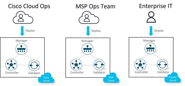
With cloud-hosted deployments, control components can be deployed in Amazon Web Services (AWS) or Microsoft Azure, and with on-premise or SP-hosted deployments, control components are deployed in a data center on ESXi or KVM. Either Virtual Machines (VMs) or containers can be deployed.
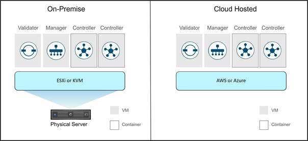
Cisco Cloud-Hosted Deployment (recommended)
Cloud-hosted deployment for the Cisco Catalyst SD-WAN control components is the recommended mode of deployment since it is Cisco-orchestrated and easy to deploy and scale with high availability. It requires reachability to the Internet in order to connect to the control components. The disadvantage is if there is not reachability to the Internet through a second transport, then there is no control connection redundancy.
The following figures are examples of cloud-hosted deployments. The control components are hosted in a public cloud and reachable via the Internet transport. The WAN Edge routers attempt to make control connections to control components over all transports. There are three common scenarios:
● In deployment A, the Internet transport is reachable from the MPLS transport through an extranet or direct-connect connection, so WAN Edge 1 can connect to the control components directly from both transports. For this, the MPLS cloud may be advertising the publicly routable IP addresses of the control components, or a default route, depending on the network.
● In deployment B, the MPLS transport has no extranet connection and instead has reachability to the Internet by being routed through a regional hub or data center site, which has connections to both transports. For this, the data center site may be advertising the publicly routable IP addresses of the control components, or a default route, depending on the network.
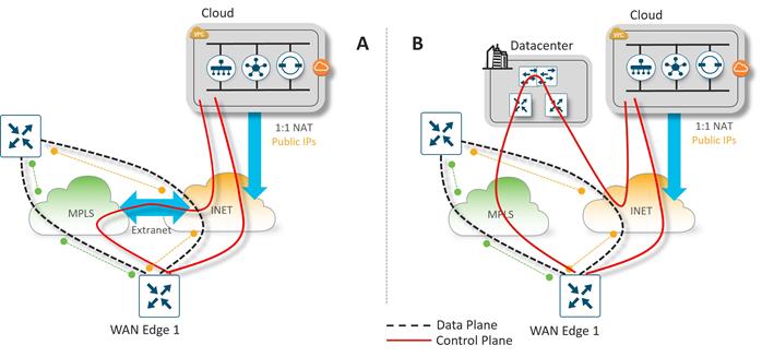
● In deployment C, the Internet transport is not reachable from the MPLS transport, so WAN Edge 1 can connect to the control components only from the Internet transport. WAN Edge 1 can still establish data plane IPsec connections over the MPLS transport because the TLOC information is still received over OMP from the Internet transport. There is no control plane redundancy should the Internet transport fail.
| Tech tip |
| Deployment C requires the use of max-control-connections 0 under the MPLS tunnel interface, which tells the WAN Edge router that the TLOC is not expected to have control connections. The MPLS TLOC is advertised via the control connection on the Internet side and data plane connections can still form with other WAN Edge routers over the MPLS transport. |
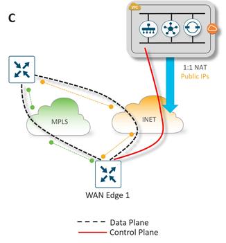
Cloud-hosted Deployment Control Components Communication
In the cloud-hosted environment, the control components sit behind a virtual gateway. Each control component is addressed with a private IP address, and the virtual gateway applies 1-to-1 NAT by translating each private controller address into a separate publicly routable IP address for reachability across the Internet.
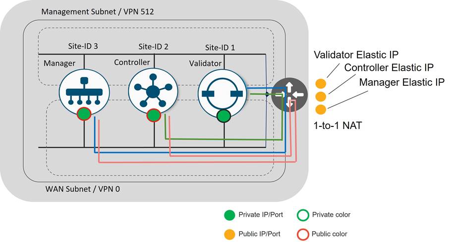
The SD-WAN Manager and SD-WAN Controllers use a public color on their tunnel interfaces. This ensures they will always use public IP addresses to communicate with any WAN Edge devices. There is no concept of color on the SD-WAN Validator interface.
The SD-WAN Controller and SD-WAN Manager have an SD-WAN Validator configuration that points to the Validator’s public IP address. When either control component attempts to communicate with the SD-WAN Validator, the traffic will traverse the gateway and the gateway applies a 1-to-1 source NAT on the private IPs of the SD-WAN Controller and SD-WAN Manager. In turn, the SD-WAN Validator communicates with the SD-WAN Controller and SD-WAN Manager using their NATed public IP addresses, so the return traffic must also traverse the gateway. It is a requirement for the SD-WAN Validator to communicate to the SD-WAN Controller and SD-WAN Manager through their public addresses so the SD-WAN Validator can learn those IP addresses and pass those public IP addresses to the WAN Edge devices wanting to connect into the overlay.
The SD-WAN Manager and the SD-WAN Controller communicate to each other via their NATed public IP addresses. This is due to their public color configuration and their site ID configurations being different. If their site IDs were equal, they would be communicating via their private IP addresses, bypassing the gateway for that communication.
On-Premise Control Component Deployment
In this type of control component deployment, control components are deployed on-premise in a data center or private cloud, where the enterprise IT organization is typically responsible for provisioning the control components and responsible for backups and disaster recovery. Some customers, such as financial institutions or government-based entities, may choose to run on-premise deployments mainly due to security compliance reasons.
The following figure are two examples of an on-premise deployment. In deployment A, WAN Edge 1 can connect to the control components in the data center from both transports. In deployment B, the control components are reachable only through the private MPLS. An additional SD-WAN Validator is deployed on the Internet and acts as a STUN server for WAN Edge devices with Internet access and redirects them to the private control component IP addresses. WAN Edge 1 can still establish data plane IPsec connections over the Internet transport because the TLOC information is still received over OMP from the MPLS transport.
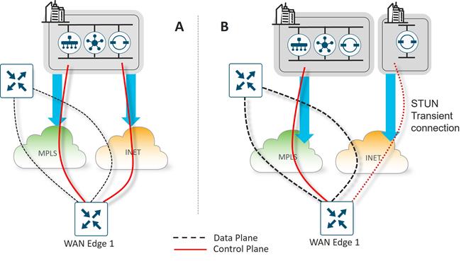
For on-premise deployments, there are multiple ways to arrange the control components using NAT, Public IPs, and/or Private IPs. The following are common options for on-premise deployments:
● Control connections are established through both the Internet and MPLS transports using publicly routable IP addresses. Publicly routable IP addresses can be assigned directly to the control components or through one-to-one NAT.
● Control connections are established through the MPLS transport using private (RFC 1918) IP addresses and established through the Internet using publicly routable IP addresses. The SD-WAN Validator can use a publicly routable IP address that is accessible from either transport or it can also be reachable via a private RFC 1918 IP address through the MPLS transport.
Control Component Redundancy/High Availability
Redundancy for the control components is achieved in different ways, depending on the control component type.
SD-WAN Validator
SD-WAN Validator redundancy is achieved by spinning up multiple SD-WAN Validators and using a single Fully Qualified Domain Name (FQDN) to reference the SD-WAN Validators. The FQDN is used in the system vbond configuration command of a WAN Edge router or SD-WAN Controller or SD-WAN Manager. It is recommended to use SD-WAN Validators in different geographic regions if managed from the cloud or in different geographic locations/data centers if deployed on-premise to maintain proper redundancy. This ensures that at least one SD-WAN Validators will always be available when an SD-WAN device is attempting to join the network.
In the Domain Name Server (DNS), multiple IP addresses are associated with the FQDN of the SD-WAN Validator. Typically, all SD-WAN Validator IP addresses are passed back to the DNS querier, and each IP address is tried in succession until a successful connection is formed. The starting point index into the DNS list is determined by a hash function. If a DNS server is unavailable, static host statements can be configured on the WAN Edge as an alternative.
Note that even if only one SD-WAN Validator exists in the network, it is recommended to use a Domain Name for the SD-WAN Validator so when additional orchestrators are added, no change of configurations are needed in the network.
Note that each SD-WAN Validator will establish permanent connections to each core of the SD-WAN Manager and SD-WAN Controller. This helps to ensure that the SD-WAN Validator does not provide the IP address of an unavailable control component to WAN Edge routers joining the network. There are no control connections between SD-WAN Validators themselves or any state kept between them.
The following figure illustrates SD-WAN Validator redundancy from a WAN Edge router using static host statements or a DNS server. Note that the WAN Edge router first needs to connect to the SD-WAN Validator over each of its transports before it can learn the IP addresses and authenticate to the SD-WAN Manager and SD-WAN Controllers.
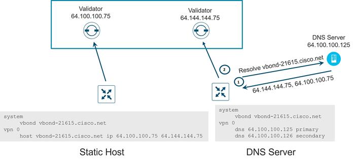
SD-WAN Controller
For SD-WAN Controllers, redundancy is achieved by adding additional Controllers which act in an active/active fashion. It is recommended to use SD-WAN Controllers in different geographic regions if managed from the cloud or in different geographic locations/data centers if deployed on-premise to maintain proper redundancy.
By default, a WAN Edge router will connect to two SD-WAN Controllers over each transport. If one of the SD-WAN Controllers fails, the other SD-WAN Controller seamlessly takes over handling the control plane of the network. As long as one SD-WAN Controller is present and operating in the domain, the network can continue operating without interruption. SD-WAN Controllers maintain a full mesh of DTLS/TLS connections to each other, over which a full mesh of OMP sessions are formed. Over the OMP sessions, the SD-WAN Controllers stay synchronized by exchanging routes, TLOCs, policies, services, and encryption keys.
| Tech tip |
| All WAN Edge routers must see identical views of the network regardless of the SD-WAN Controllers they connect to, so it is extremely important that all control policies are identical on each SD-WAN Controller. If all SD-WAN Controllers are managed by the SD-WAN Manager, then their control policies will be identical since the SD-WAN Manager applies the centralized policy to all SD-WAN Controllers. |
You can control the number of SD-WAN Controller connections a WAN router makes with the SD-WAN Controllers over each TLOC with the max-control-connections command under each interface tunnel in VPN 0. The default setting is two. In addition, there is a max-omp-sessions command under the system configuration that can also be adjusted. Its default configuration is also two. Note that any number of connections made to the same SD-WAN Controller is considered part of the same OMP session. When there are more SD-WAN Controllers in the network than the WAN Edge max-control-connections allow, the WAN Edge router control connections will be hashed to a subset of SD-WAN Controllers.
In the following diagram, the WAN Edge makes two DTLS or TLS control connections over each transport, one to each SD-WAN Controller. OMP rides over this connection. The connections from each TLOC are limited by the max-control-connections command (2), and the total OMP sessions are limited by the max-omp-sessions command (2).
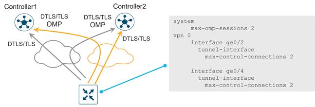
SD-WAN Controller Affinity
As your network grows and more SD-WAN Controllers are added to the network and distributed globally, affinity allows you to manage scale and prefer which SD-WAN Controllers your WAN Edge routers connect to. This is important if you want to ensure your WAN Edge devices connect to Controllers in the same geographic region and helps ensure you connect to the proper SD-WAN Controllers for redundancy. For example, if you have two SD-WAN Controllers in the West data center, and two SD-WAN Controllers in the East data center, and your WAN Edge routers connect to two SD-WAN Controllers, you do not want one WAN Edge router to connect to both SD-WAN Controllers in the West data center. For proper redundancy, you would want one connection to an SD-WAN Controller in the West data center, and one connection to an SD-WAN Controller in the East data center.
You can achieve affinity by using controller groups. Each SD-WAN Controller is assigned to a controller group. Within a controller group, a WAN Edge router connects to an SD-WAN Controller. When that SD-WAN Controller becomes unavailable, the WAN Edge will attempt to connection to another SD-WAN Controller in the same controller group.
It is recommended to minimize the number of connections made to the SD-WAN Controllers yet still maintain a good level of redundancy. By default, the max-control-connections on each TLOC is two and the max-omp-sessions is two, so the WAN Edge device establishes connections with, at most, two different SD-WAN Controllers. The SD-WAN Controllers are configured with a controller group-id, and the WAN Edge routers are configured with the controller group list, in order of priority of which group ID’s to connect to.
The following figure shows an example of how affinity can be used in a regional deployment. The diagram shows four data centers, with SD-WAN Controllers as part of controller-group-id 1 in data center 1, controller-group-id 2 in data center 2, controller-group-id 3 in data center 3, and controller-group-id 4 in data center 4. Each DC is in a different region.
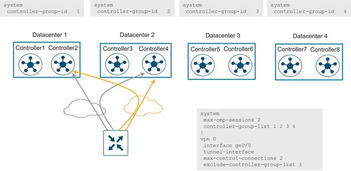
The following is configured on the WAN Edge router:
● max-omp-sessions 2: the WAN Edge device can attach up to 2 different SD-WAN Controllers (there is one OMP session established per SD-WAN Controller, regardless of the number of DTLS/TLS sessions formed between two devices).
● max-control-connections 2: the WAN Edge device can attach to two SD-WAN Controllers per TLOC.
● controller-group-list 1 2 3 4: indicates which control groups the WAN Edge router belongs to, in order of preference. The router is able to connect to Controllers that are in the same controller group. The WAN Edge router attempts to attach to all controller groups not explicitly excluded based on the current state of the Controller and the WAN Edge configuration session limits. In this example, the router first attempts to connect to an SD-WAN Controller in group 1 and then one in group 2 in each transport. Note that the software evaluates the controller group list in the order that it appears in the configuration. All controller groups, including excluded ones, should be included in this list.
● exclude-controller-group-list 3: Exclude the non-preferred SD-WAN Controller controller group for a particular tunnel. The controller groups listed in this command must be a subset of the controller groups configured in the controller-group-list command.
If an SD-WAN Controller in controller-group-id 1 becomes unavailable, the WAN Edge router will attempt to connect to another SD-WAN Controller in controller-group-id 1. If controller-group-id’s 1 and 2 are both unavailable, the WAN Edge router will attempt to connect to another available group in the controller-group-list (4) excluding controller-group-id 3, or any other group defined by the exclude-controller-group-id command. If no other controller groups are listed in the controller-group-list, as a last resort, the router will make a connection attempt to an SD-WAN Controller excluded in the controller-group-list to avoid complete loss to the SD-WAN overlay.
It is recommended that the number of SD-WAN Controllers in each controller group be the same, and each SD-WAN Controller should have the same hardware resource capabilities across the network.
SD-WAN Manager Network Management System (NMS)
The SD-WAN Manager can be deployed in two basic ways, either standalone or by clustering. All SD-WAN Manager instances inside a primary cluster operate in active mode. The purpose of an SD-WAN Manager cluster is scale. It does provide a level of redundancy against a single SD-WAN Manager failure, but it does not protect against a cluster-level failure. Clustering across geographical locations is not recommended, as database replication between cluster members requires 4 ms or less of delay between them. Therefore, members of a cluster should reside at the same site. Redundancy is achieved with a backup SD-WAN Manager or backup SD-WAN Manager cluster in standby mode.
The SD-WAN Manager can be deployed as a single node, a 3-node cluster, or a 6-node cluster. It is recommended to deploy one node or cluster as primary and one as backup. It is recommended to deploy primary and backup at two different geographical locations to achieve redundancy.
WAN Edge routers connect to an SD-WAN Manager over one of the transports. You can control which transport is used with the vmanage-connection-preference <number> command under the tunnel interface on a WAN Edge. To prefer a specific tunnel interface to use to connect to the SD-WAN Manager, use a higher preference value. Try to use the highest bandwidth link for the SD-WAN Manager connection and avoid cellular interfaces if possible. A zero value indicates that tunnel interface should never connect to the SD-WAN Manager. At least one tunnel interface must have a non-zero value.
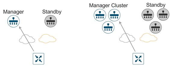
Note that in Cisco-hosted cloud deployments, standby SD-WAN Manager instances are not deployed. Cisco Cloud Ops takes care of SD-WAN Manager backups and disaster recovery.
When sizing SD-WAN Manager resources, not only do the number of WAN Edge devices need to be considered, but also the volume of statistics expected to be received, processed, and stored by the SD-WAN Manager from the WAN Edge routers.
Cisco Catalyst SD-WAN Application Intelligence Engine (SAIE)
Cisco Catalyst SD-WAN Application Intelligence Engine (SAIE) is the architecture for application classification. It can determine the contents of the packet for application visibility and can record the information for statistics collection. When application visibility is enabled through localized policy, flow records are enabled on the router and NBAR2 is used as the application classification engine on the WAN Edge router. Traffic flow statistics and its classification information are sent to the SD-WAN Manager, then collected and processed, where it can be displayed on the SD-WAN Manager GUI.
WAN Edge routers store statistics or aggregated statistics (starting in 20.6/17.6 code) and the SD-WAN Manager pulls this data from each WAN Edge router at pre-defined intervals and is processed/analyzed and stored on the SD-WAN Manager. Note that these statistics not only include SAIE statistics data but also other statistics, such as interface stats, QoS, App-route stats, firewall stats, etc. SAIE statistics typically make up a larger proportion of the statistics data.
Statistics generated can be estimated on a running system using the API call, https://<SD-WAN Manager IP>/dataservice/management/elasticsearch/index/size/estimate.
SD-WAN Manager clustering
An SD-WAN Manager cluster can distribute the various NMS service loads and provide high availability and scalability for the SD-WAN Manager services. An SD-WAN Manager cluster consists of at least three SD-WAN Manager server instances, each being active and running independently. Control connections between the SD-WAN Manager servers and WAN routers are load-balanced as well. Control connections (from each SD-WAN Manager instance to each SD-WAN Controller, from each SD-WAN Manager instance to each other SD-WAN Manager instance, and from each SD-WAN Manager instance core to each SD-WAN Validator) are fully meshed.
Note that an SD-WAN Manager cluster should be designed to tolerate a failure of a single SD-WAN Manager server while the cluster remains operational, but for high availability, a standby cluster should be deployed in the event of a cluster failure or connectivity failure to the site where the SD-WAN Manager cluster resides.
The SD-WAN Manager server runs several major services. They include:
● Application server: This is the web server (GUI) for the administrator sessions. The user can view status and network events, and can manage certificates, software, device reboots, and the SD-WAN Manager cluster configuration.
● Statistics database: This stores statistics data, audit logs, alarms, and events from all of the SD-WAN devices in the overlay network.
● Configuration database: This stores the device inventory, policies, certificates, and the configuration and state of the SD-WAN devices.
● Messaging server: This service passes messages, shares data, and coordinates operations between the SD-WAN Manager devices in the cluster. The SD-WAN Manager devices share information over the message bus between them, which is a separate interface in VPN 0 specifically for communication with devices in the cluster.
● Network configuration system: This system is responsible for pushing configurations to the SD-WAN devices and for retrieving configurations from the SD-WAN devices.
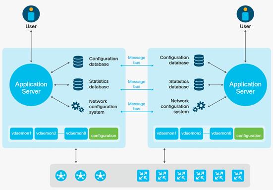
The following are things to keep in mind while deploying an SD-WAN Manager cluster:
● For clustering purposes, a third interface is required besides the interfaces used for VPN 0 (transport) and VPN 512 (management). This interface is used for communication and syncing between the SD-WAN Manager servers within the cluster. This interface should be at least 1 Gbps and have a latency of 4 ms or less. A 10 Gbps interface is recommended.
● In ESXi, it is recommended to use VMXNET3 adapters for interfaces. VMXNET3 supports 10 Gbps speeds. To make VMXNET3 NICs available, under ESXi 5.0 and later (VM version 8) compatibility settings, under Edit Settings>VM Options>General Options, choose a Guest OS version that supports VMXNET3 (such as Ubuntu Linux (64-bit) or Red Hat Linux 5 (64-bit) or greater).
● The configuration and statistics service should be run on at least three SD-WAN Manager devices. Each service must run on an odd number of devices because to ensure data consistency during write operations, there must be a quorum, or simple majority, of SD-WAN Manager devices running and in sync.
● Changes to a cluster may require services to restart and the cluster to resync. Any cluster configuration changes should be done during a maintenance window.
Disaster Recovery
The SD-WAN Validator and SD-WAN Controllers are stateless. Snapshots of their virtual machines can be made before any maintenance or configuration changes, or their configurations can be copied and saved if running in CLI mode. In addition, if feature or CLI templates are configured on the SD-WAN Manager (required for SD-WAN Controllers if centralized policies are built and applied from the SD-WAN Manager), their configurations will be saved with the SD-WAN Manager snapshots and database. Snapshots can be restored or the device can be re-deployed and configuration templates pushed from the SD-WAN Manager in a disaster recovery scenario.
The SD-WAN Manager is the only stateful SD-WAN control component, and its backup cannot be deployed in active mode. For the SD-WAN Manager server, snapshots should be taken, and the database backed up regularly.
There are different disaster recovery methods available. In common disaster recovery scenarios, an active SD-WAN Manager or SD-WAN Manager cluster resides at one data center site, along with at least one active SD-WAN Controller and SD-WAN Validator. In a second data center, a standby (inactive) SD-WAN Manager or SD-WAN Manager cluster is deployed, along with at least one active SD-WAN Controller and SD-WAN Validator. On the active SD-WAN Manager or SD-WAN Manager cluster, each SD-WAN Manager instance establishes control connections to SD-WAN Controllers and SD-WAN Validators in both data centers. When the standby SD-WAN Manager or SD-WAN Manager cluster becomes active, it then establishes control connections to the SD-WAN Controllers and SD-WAN Validators in both data centers.
The following disaster recovery methods are available:
● Manual (SD-WAN Manager standalone or cluster) – The backup SD-WAN Manager server or SD-WAN Manager cluster is kept shutdown in cold standby state. Regular backups of the active database are taken, and if the primary SD-WAN Manager or SD-WAN Manager cluster goes down, the standby SD-WAN Manager or SD-WAN Manager cluster is brought up manually and the backup database restored on it.
● Administrator-triggered failover (SD-WAN Manager standalone or cluster) (recommended)– The administrator-triggered disaster recovery switchover option can be configured on a cluster starting in version 19.2 or on a single node starting in version 20.5.1. Data is replicated automatically between the primary and secondary SD-WAN Manager nodes/clusters. When needed, a switchover is manually performed to the secondary SD-WAN Manager node/cluster.
Control Component Scaling
Scaling for each control component may change from one release to another. Please refer to https://www.cisco.com/c/en/us/td/docs/routers/sdwan/release/notes/compatibility-and-server-recommendations/server-requirements.html and check the Recommended Computing Resources for Cisco Catalyst SD-WAN Control Components for your specific release to get vCPU, RAM, and storage requirements and number of control components required for your deployment. The documentation also lists the max number of instances of each control component that have been tested in a single overlay. The number of Cisco SD-WAN Controller and Validator instances recommended assumes a control component deployment in two locations (data centers or cloud regions) and is designed for redundancy, where half of the controllers is deployed in one location and the other half is deployed in the other location. It also assumes 2 TLOCs per WAN Edge router with no Controller group/affinity configuration.
| Tech tip |
| If your control component deployment design uses a different set of assumptions, such as additional data centers, more TLOCs, and Controller group/affinity configuration and you need additional design assistance, reach out to Cisco Sales to help validate the design before deployment. |
Refer to the Cisco SD-WAN Large Global WAN Design Case Study for more information on how to design for large-scale SD-WAN networks.
Control Component Deployment Examples
Control components can be deployed in several different ways. The following show a few examples of regional and global control component deployments for a set number of WAN Edge devices. As you are design planning, ensure if there is a single device failure or if there is an entire data center in a region that cannot be reached, the remaining control components should be able to service the rest of the network. When designing using SD-WAN Controller affinity, be aware of how many connections a group can service and if your design expects to service WAN Edge routers in times of failure, ensure there is available capacity to service the required number of connections if another affinity group fails. Note also that WAN Edge routers need just one SD-WAN Connection in a failure scenario to ensure no traffic/routing interruption and SD-WAN Validators are needed by WAN Edge routers when joining or re-joining the network through a new deployment, device reload, interface reset, etc, or when the WAN Edge device goes “out of equilibrium” and loses control or OMP connections to its other control components during an outage.
1. Minimal control component design: Here are two examples of a network with 1000 devices or less with Cisco Catalyst SD-WAN Application Intelligence Engine (SAIE) disabled. It assumes 2 transports/TLOCs per WAN Edge router running on the 20.9.x release.
◦ In this regional example, this design contains 1 active and 1 standby SD-WAN Manager, 2 SD-WAN Validators, and 2 SD-WAN Controllers, split between two different regions.
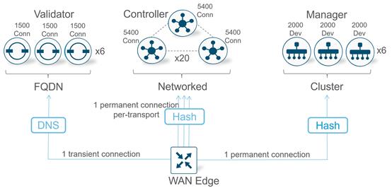
◦ In this example, control components are centered in different geographical regions spread across the globe. This design contains 3 SD-WAN Validators, 3 SD-WAN Controllers, and 1 active and 1 standby SD-WAN Manager. SD-WAN Controller affinity is used so WAN Edge devices connect to the SD-WAN Controllers in the two closest geographical areas (North America and Europe, or Europe and Asia as examples).
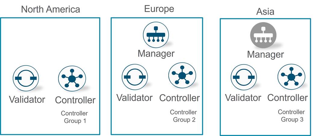
2. Small control component design (4000 devices). Here is an example of a network with 4000 devices with Cisco Catalyst SD-WAN Application Intelligence Engine (SAIE) disabled. It assumes 2 transports/TLOCs per WAN Edge router running on the 20.9.x release.
◦ In this example, this design contains 1 active and 1 standby SD-WAN Manager cluster, each with 3 SD-WAN Manager instances. It also includes 4 SD-WAN Validators, 4 SD-WAN Controllers, split between multiple sites within a region or globally. SD-WAN Controller affinity is used to so WAN Edge devices can connect to the SD-WAN Controllers in the two closes geographical areas.
Note that according to the documentation, only 2 Validators are required, but in this example, a validator is being deployed in every location along with a Controller. Alternatively, this network could be deployed with 2 data centers, each with 2 controllers and 1 or 2 Validators.
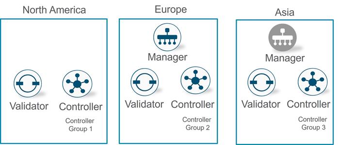
WAN Edge routers are deployed at the remote sites, campuses, and data centers and are responsible for routing data traffic to and from the sites across the SD-WAN overlay network.
When deploying a WAN Edge router for a site, the platform should be chosen and sized properly for traffic throughput and the number of tunnels supported, etc. A second WAN Edge router is recommended to be added for redundancy. When deploying, WAN Edge routers are commonly connected to all transports for proper redundancy.
The following figure illustrates a single router and dual-router site, with each WAN Edge router connecting to both transports.
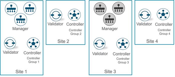
IPsec-encapsulated tunnels encrypt data traffic to other WAN Edge router locations, and BFD sessions are also formed over these tunnels. User traffic originating from the service VPNs is directed to the tunnels. When a transport or link to a transport goes down, BFD times out and the tunnels are brought down on both sides once the WAN Edge routers detect the condition. The remaining transport or transport links can be used for traffic. In the dual-router site, if one of the routers fail, the remaining router which still has connections to both transports takes over the routing for the site.
Transport Side
Underlay
The underlay includes the transport VPN (VPN 0) and the connections to each transport. For simplicity, it is recommended to use static routing in VPN 0 whenever possible as opposed to dynamic routing, however, dynamic routing in VPN 0 may be needed to advertise loopback or TLOC extension interfaces. It also might be needed in certain sites where underlay routing must be performed to connect to legacy networks. Regardless, care should be taken to not mix the underlay network with the overlay network wherever possible. BGP, OSPF, and RIP v1/2 (IOS XE SD-WAN only) are dynamic routing protocols which are supported in the transport VPN.
Typically, all that is needed for routing in VPN 0 is a default route specifying the next hop IP address for each transport. Its purpose is to build IPsec-encapsulated data tunnels to other WAN Edge routers and build control plane DTLS/TLS tunnels to the SD-WAN control components. Multiple default routes can exist within VPN 0 because the route that is chosen depends on the tunnel source IP address, which should be in the same subnet as the default-route next-hop IP address.
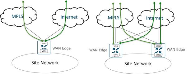
Connection Choices
All that is needed to establish the underlay is IP connectivity from the WAN Edge router to the transport service provider, who is responsible for propagating the tunnel subnet route information to the remote SD-WAN sites. The connection to the transport can be made in multiple ways although it is recommended to be positioned as close to the transport as possible.
The following are common connection choices:
● (A) For MPLS, a WAN Edge router can completely replace a Customer Edge (CE) router so there is direct connectivity from the WAN Edge router to the Provider Edge (PE) router in the MPLS transport. For the Internet transport, a WAN Edge router is connected directly to the Internet transport with no firewall present. This connection type is commonly seen in branch sites.
● (B) For MPLS, a WAN Edge router can be placed behind a CE router which connects to the MPLS transport. This is used when the CE router must remain in place for reasons such as:
◦ The CE router provides network connectivity or a network service with a feature enabled not supported by the SD-WAN router, such as SRST/voice or DLSW.
◦ The CE router provides direct access to non-migrated SD-WAN sites during an SD-WAN deployment.
◦ The CE router needs to remain in place in order to introduce SD-WAN at a site with minimal disruption.
For the Internet transport, the WAN Edge router can be placed behind a firewall if it is required by the company security policy. This connection type is commonly seen in data center sites.
● (C) For both MPLS and Internet transports, a WAN Edge router can be connected directly to the LAN switch for transport connectivity when a CE or Firewall is required but no direct connection is available to the CE or Firewall for the SD-WAN router.
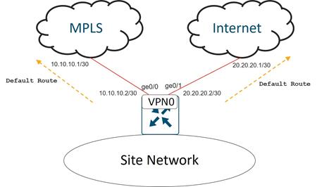
SD-WAN Routers and Firewalls
SD-WAN routers do not need to sit behind firewalls but can if the security policy dictates. It is typical for a WAN router in the branch to connect directly to the transport and not sit behind a separate firewall appliance. When tunnels are configured on the transport physical interface of a WAN Edge router, the physical interface of the WAN Edge router is restricted to only a limited number of protocols by default. By default, DHCP, DNS, ICMP, and HTTPs native packets are allowed into the interface in addition to DTLS/TLS and IPsec packets. SSH, NTP, STUN, NETCONF, and OSPF and BGP native packets for underlay routing are turned off by default. It is recommended to disable whatever is not needed and minimize the native protocols you allow through the interface. In addition, the WAN Edge router can only form IPsec connections with other WAN Edge routers who have been allowed into the SD-WAN overlay through certificate authentication and only by devices included and authorized on the WAN Edge authorized serial number list.
Note that if a firewall is positioned in front of a WAN Edge router, most traffic cannot be inspected by the firewall since the firewall sees AES 256-bit encrypted IPsec packets for WAN Edge router data plane connections and DTLS/TLS-encrypted packets for WAN Edge control plane connections. If a firewall is used, however, IPsec and DTLS/TLS connections for the SD-WAN router need to be accommodated by opening the required ports on the firewall. If NAT needs to be applied, one-to-one NAT is recommended, especially at the data center site. Other NAT types can be used at branches, but symmetric NAT can cause issues for data plane connections with other sites, so exercise caution when deploying.
Note that for direct Internet traffic and PCI compliance use cases, the IOS XE SD-WAN router supports its own native, full security stack, which includes an application firewall, IPS/IDS, malware protection, and URL filtering. This security stack support eliminates the need to have additional security hardware deployed and supported at a remote site. The vEdge router supports its own zone-based firewall. Both router types can integrate with Cisco Umbrella as a Secure Internet Gateway (SIG) for cloud-based security. For more information on the IOS XE SD-WAN security features, see the Security Policy Design Guide for Cisco IOS-XE SD-WAN Devices.
TLOC Extension
There are times when WAN Edge routers cannot be connected to each transport directly and only one WAN Edge router can be connected to a single transport.
Alternatively, a switch can be connected to each transport and the SD-WAN routers can connect to each transport through the connected switches. This is not usually recommended at a branch because it adds cost to the solution and results in having another device to manage.
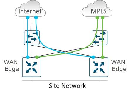
TLOC extensions allow each WAN Edge router to access the opposite transport through a TLOC-extension interface on the neighboring WAN Edge router. In the figure below, WAN Edge 1 connects directly to the MPLS transport and uses the TLOC extension interface on WAN Edge 2 to connect to the INET transport. In turn, WAN Edge 2 connects directly to the INET transport and uses the TLOC extension interface on WAN Edge 1 to connect to the MPLS transport. The connection from a TLOC extension interface through to a transport is transparent. WAN Edge 1 router in the diagram still has two physical interfaces with tunnels configured – one to the MPLS and one to the Internet and is unaware the tunnel to the Internet passes through another SD-WAN router.
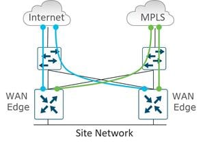
TLOC Extension Types
TLOC extensions on SD-WAN routers can be connected in multiple ways. SD-WAN routers can be directly connected, connected through an L2 switch, or connected through an L3 switch/router. L2 TLOC extensions describe TLOC extensions between two routers which are L2-adjacent to each other and the links are in the same subnet. L3 TLOC extensions describe TLOC extensions between two routers separated by an L3 switch or router where the links are in different subnets. L3 TLOC extensions are implemented using GRE tunnels. Note that TLOC extensions can be separate physical interfaces or subinterfaces (if bandwidth allows). L2 TLOC extensions can also be configured over a port-channel starting in code version 20.13.1/17.13.1a, when EtherChannel support on the transport side is introduced.
The following illustrates different L2 and L3 TLOC extension deployments.
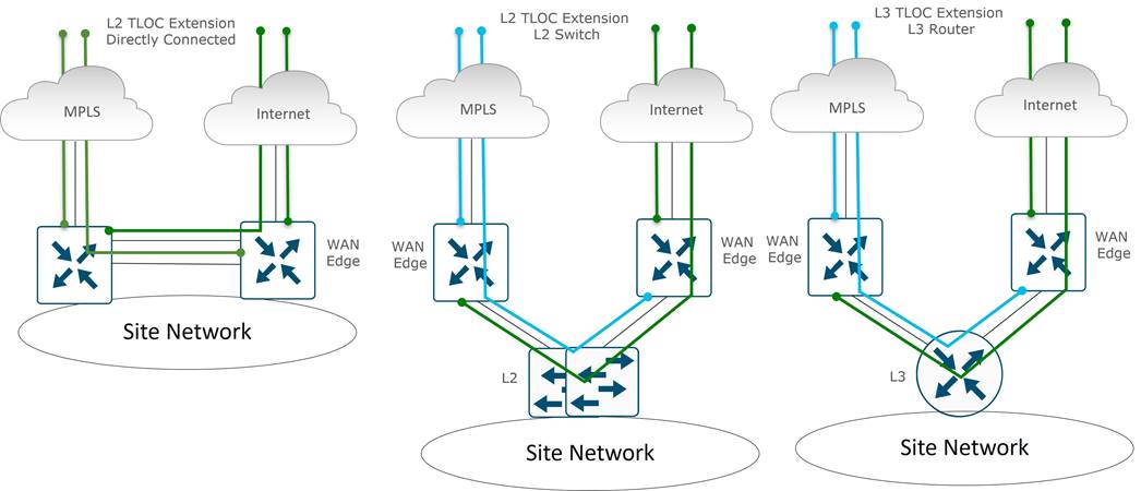
There are some limitations with the use of TLOC extensions:
● An LTE WAN interface cannot be used as a TLOC extension interface between WAN Edge routers.
● A TLOC extension interface cannot be used to extend an LTE WAN interface, however, it can be used to extend an ethernet interface which is connected to an LTE modem.
● L3 TLOC extension is only supported on IOS XE SD-WAN routers – they are not supported on vEdge routers.
TLOC Extension Routing
When you configure the TLOC extension interface, you configure it in VPN 0, assign it an IP address, and then specify the WAN interface to which it is bound. In the below figure, WAN Edge 1’s TLOC extension interface is ge0/7 and is bound to the MPLS transport through ge0/2. WAN Edge 2's TLOC extension interface is ge0/7 and is bound to the INET transport through ge0/4.
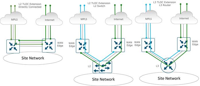
Some routing considerations need to take place in order for control component reachability to occur and for IPsec tunnels and BFD sessions to come up with other sites over the TLOC extension interfaces. Static default routes should be configured in the underlay (transport VPN 0) on each WAN Edge router, pointing to the Service Provider router as the next hop.
To reach the INET transport, WAN Edge 1’s INET interface (ge0/4) should be configured with a default route pointing to WAN Edge 2’s ge0/7 IP address. If subnet A is in a private address space, then NAT should be configured on WAN Edge 2’s ge0/4 transport interface to ensure traffic can be routed back from the Internet to WAN Edge 1 over the TLOC Extension.
To reach the MPLS transport, WAN Edge 2’s MPLS interface should be configured with a default route pointing to WAN Edge 1’s ge0/7 IP address. To ensure traffic can be routed back to the TLOC extension interface, a routing protocol (typically BGP, or OSPF) can be run in the transport VPN (VPN 0) of WAN Edge 1 to advertise subnet B so that the MPLS provider has a route to subnet B through WAN Edge 1. Typically, a route map is also applied inbound to deny all incoming dynamic routes from the service provider since the static default route is used in the transport VPN for control plane and IPsec tunnel establishment. As an alternative to a routing protocol, the MPLS PE router can implement a static route to subnet B through WAN Edge 1 which can then be redistributed through the service provider network. Static routes are not recommended because the method is not as manageable or scalable as using a dynamic routing protocol when you have a large number of sites.
Transport Choices
There are a many different transport choices and different combinations of transports that can be used. Transports are deployed in an active/active state, and how you use them is extremely flexible. A very common transport combination is MPLS and Internet. MPLS can be used for business-critical traffic, while Internet can be used for bulk traffic and other data. When one transport is down, the other transport can be used to route traffic to and from the site. Internet is reliable in most places and able to meet the SLAs of most applications, so often sites will deploy 2 Internet transports instead.
LTE is used frequently as a transport choice and can be deployed in active mode or as a circuit of last resort, which doesn’t become active unless all other transports become unavailable.
The following shows a small sample of different transports options. Picture C shows TLOC Extensions on separate physical interfaces while Picture D shows multiple TLOC extensions using subinterfaces across two physical interfaces.
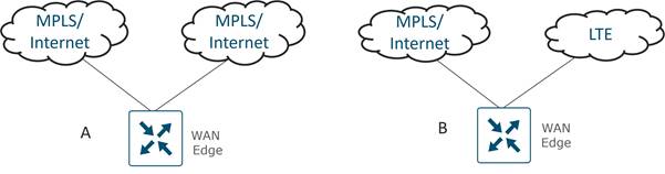
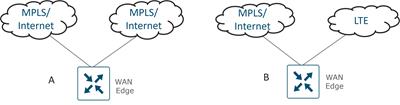
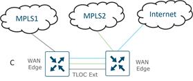
| Tech tip |
| Note that there are limits to the number of concurrent transports. On a WAN Edge router, you can configure up to eight tunnel interfaces, which is equivalent to eight TLOCs. |
Equal-Cost Multipath (ECMP) for Tunnels
Between two SD-WAN sites, by default, a tunnel is built from one SD-WAN router over each transport to each SD-WAN router at the remote site. This could result in several equal-cost multipath tunnels to the same site and traffic can traverse any one of these paths to reach its destination, using a hash on key fields in the IP header to determine what path to take.
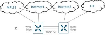
For a vEdge router by default, a combination of source IP address, destination IP address, protocol, and DSCP value is used as the hash key to determine which equal-cost path to pick. The option Enhance ECMP Keying can be chosen from the SD-WAN Manager GUI (or ecmp-hash-key layer4 from the CLI) in order to include L4 source and destination port information in the hash key calculation. To affect traffic distribution across tunnels, the configuration changes are made in the service VPNs. To affect traffic distribution of underlay routing and direct Internet access, the configuration changes are made in the transport VPN (VPN 0).
For the IOS XE SD-WAN router, hashing for choosing a path is done based on source and destination IP address, and source and destination port number. There are no additional options.
TLOC Preference
By default, all TLOCs on a WAN Edge router are assigned the same preference with the value 0. All TLOCs are advertised into OMP, and the router uses ECMP to distribute traffic among the tunnels. A tunnel can be assigned a preference of any value from 0 through 4294967295 (2^32 – 1)). Traffic is influenced in both outbound and inbound directions and depends on the preference values of the remote TLOCs as well.
Weight
The weight parameter can be used to send traffic over weighted tunnels, where a higher value sends more traffic to a tunnel compared to another. Weight is often used when the bandwidth of the TLOCs vary and you cannot perform ECMP over the links. Weight can be set from 1 to 255, with a default value of 1. Traffic distribution takes into account the remote TLOC weight as well as the local TLOC weight.
Tunnel Groups
By default, WAN Edge routers try to build tunnels to all other TLOCs, regardless of color. When the restrict option is used with the color designation under the tunnel, the tunnel is restricted to only building tunnels to TLOCs of the same color. The tunnel group feature is similar to this feature but gives more flexibility because once a tunnel group ID is assigned under a tunnel, only TLOCs with the same tunnel group IDs can form tunnels with each other irrespective of color. TLOCs with any tunnel group ID will also form tunnels with TLOCs that have no tunnel group IDs assigned. The restrict option can still be used in conjunction with this feature. If used, then an interface with a tunnel group ID and restrict option defined on an interface will only form a tunnel with other interfaces with the same tunnel group ID and color.
Here are a few use cases that use tunnel groups:
● The following diagram illustrates a branch that uses a different private color compared to two other branches. Using tunnel groups would allow all private transports to make tunnel connections together while still keeping all separated from the public transport, since the public transport is assigned a different tunnel group ID. No restrict option is enabled.
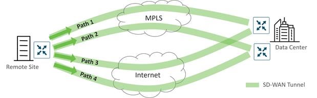
In the following use case, a WAN Edge router has two connections to the same transport. On WAN Edge routers, a color cannot be used on more than one interface, so a different color has to be assigned to each interface. Tunnel groups can be used in this case so both interfaces can build tunnels to the same branches, and traffic leaving the WAN Edge router can use ECMP to load-share traffic across both interfaces.
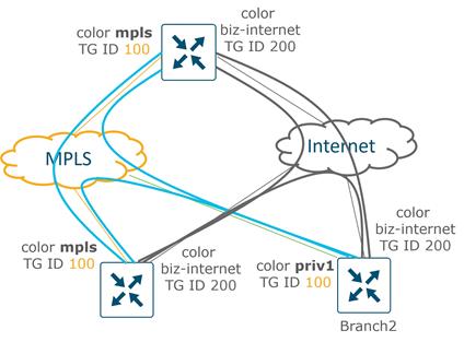
Tunnel groups can also be used to create groupings of meshed tunnels within a site or region. In the following example, two companies have merged and communicate to each other only through two centralized hub routers. Each company WAN Edge router communicates in a full mesh to the same company WAN Edge routers. Each WAN Edge branch router is assigned to either tunnel group id 100 or 200. The hub routers do not have tunnel group IDs defined on their tunnel interfaces, so those TLOCs form tunnels with all other tunnel group IDs (in the absence of the restrict option).
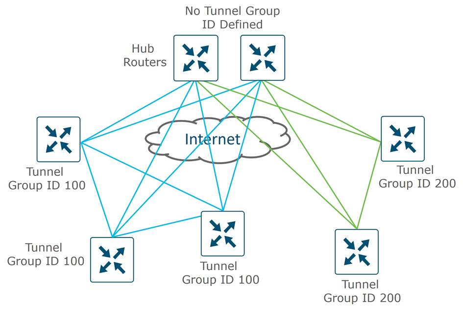
Loopback Interface Tunnels
There are times that physical interfaces cannot be used as tunnel interfaces, and loopback interfaces need to be configured with tunnel interfaces instead. In each case, the loopback interface must be reachable so the WAN Edge router can establish data plane connections to other WAN Edge routers and control plane connections with the SD-WAN control components. For the MPLS transport, this often means that the loopback is advertised through a dynamic routing protocol, typically BGP. For the Internet transport, NAT is typically enabled so that the loopback interface IP address is routable. Loopback Interface tunnels can be in bind or unbind mode. Bind means the loopback interface is tied to a physical interface, and all traffic to/from that loopback enters/exits from that physical interface. Unbind means that traffic to/from that loopback follows the underlay routing path. The following are example use cases for using loopback tunnel interfaces:
● If the MPLS Service Provider IP address space is being filtered or the address isn’t being advertised by the Service Provider, you cannot use the address space as the tunnel endpoint. You can use a loopback interface instead to source the tunnel, then bind the tunnel to the MPLS physical interface.
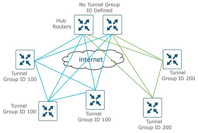
● If there are multiple interfaces connected to the same transport (for the purpose of more bandwidth, for example), different colors must be used on each transport since a specific color cannot be assigned to more than one interface on a WAN Edge router. Alternatively, the tunnel can be configured on a loopback interface, and ECMP can be used to route the traffic out the physical interfaces to the transport network. Unbound loopback interfaces use underlay routing, so more specific routes are needed out the MPLS underlay to ensure that the loopback interface tunnel traffic does not get routed out the Internet transport.
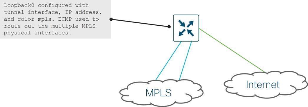
| Tech tip |
| Note that loopback tunnel interfaces can be used when traffic needs to be routed from one interface in VPN 0 to another interface in VPN 0 to avoid the implicit ACL that is used on the TLOC configured on the inbound physical interface. When loopback tunnel interfaces are bound to physical interfaces with no TLOC defined on the physical interface, the traffic inbound is still subjected to an implicit ACL starting in vManage version 20.6.1/IOS XE SD-WAN version 17.6.1a. In these cases, explicit ACLs could be used instead of defining unbound loopback interface tunnels. If you need to use loopback tunnels in bind mode but still need underlay routing to occur, explicit ACLs are required to permit underlay routing. See the product documentation for more information. |
● In an inline DC WAN Edge deployment, control traffic incoming from the MPLS may need to reach cloud-based control components on the Internet. Traffic could be routed between MPLS and Internet in VPN 0. In this case, the tunnel configuration can be removed from MPLS and placed on a separate loopback interface (unbound) so the MPLS TLOC can also reach the Internet controllers through the Internet transport. More specific routes are needed out the MPLS underlay to ensure loopback interface tunnel traffic gets routed properly.
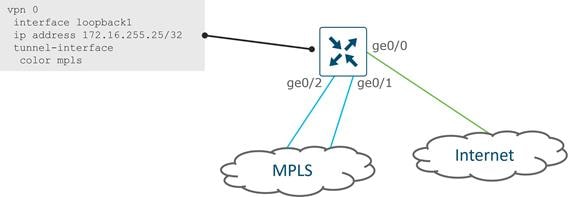
Service Side
Tunnels are built over each transport. Local site prefixes, along with the associated TLOCs, or next hops, are redistributed into OMP. Note that connected and static routes are redistributed by default. Prefixes are also received from other sites via OMP and can be redistributed into the local site’s routing protocol, if it exists. User traffic in the service VPNs can then be directed to the overlay tunnels.
For dual-router sites, redundancy on the service side VPNs can be achieved with routing (layer 3) or VRRP (layer 2).
Layer 3 Redundancy
For routers that are a hop or more away from the hosts, a routing protocol can be used for site redundancy. WAN Edge routers operate in active/active mode and run OSPF, BGP, EIGRP, or RIPv1/2 between the WAN Edge router and LAN Switch/router. Note that EIGRP and RIP are supported only on IOS XE SD-WAN routers. From the LAN switch, prefixes for remote sites appear as equal cost paths to the SD-WAN fabric. The routing protocols can be modified to prefer one WAN Edge over the other as primary for traffic. In order to send prefixes from the site, the routing protocol is redistributed into OMP and to import prefixes into the site, OMP needs to be redistributed into the routing protocol.
| Tech tip |
| When routes are redistributed into OMP, the route metric is also included as an OMP attribute. While OMP metric influences route preference across the SD-WAN fabric, the preferred method to influence traffic flow is through configuring TLOC preference or OMP route preference. |
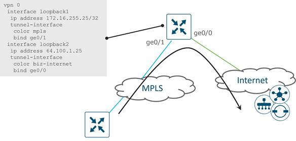
BGP
BGP as a routing protocol is supported both in the underlay to peer with CE routers or service providers and in the overlay on the service side to peer with routers at the local site. By default, BGP is not redistributed into OMP nor are routes redistributed from OMP to BGP, so redistribution in both directions must be explicitly configured.
There are a few loop prevention methods used specifically in SD-WAN:
● The Site of Origin (SoO) extended community is used and is in the form 0:<site ID>. The purpose is to keep OMP from redistributing a BGP route into a site which originated from the same site (by comparing the site ID to the locally configured site ID).
● By default, AS-Path information is not included when BGP is redistributed into OMP. To include AS-Path information for loop prevention, use the propagate-aspath command.
● For networks that use BGP for both overlay and underlay routing, an AS number can be assigned to OMP itself and can be included in the AS path of the BGP routing updates. Under OMP, this command is overlay-as <AS-number>.
When a BGP route is redistributed into OMP, the origin protocol (eBGP, for example) and metric (MED) is redistributed into OMP, along with the AS path information if the propagate-aspath command is enabled. The metric that is carried in OMP can influence which WAN Edge router at a site is preferred from the remote site over the SD-WAN fabric. The metric with the lowest value is preferred.
On the service side, as-path, local-preference, metric (MED), community, and weight are among the parameters that can be set on BGP routes.
OSPF
The routing protocol OSPF is supported both in the underlay to peer with CE routers or service providers and in the overlay on the service side to peer with routers at the local site. By default, only inter-area and intra-area OSFP routes are advertised to OMP. Redistribution of external OSPF routes into OMP, and redistribution of OMP routes into OSPF must be explicitly configured.
For loop prevention, routes are redistributed from OMP to OSPF as an external OSPF route and the DN bit is set. This prevents other routers from redistributing the route. For the SD-WAN router that receives the OMP to OSPF redistributed route, the OSPF route with the DN bit set is received and assigned an Administrative Distance (AD) of 251 on a vEdge router and 252 on an IOS XE SD-WAN router (AD is one more than the AD on the OMP routes). If OMP disappears, the redistributed route can then be installed in the routing table.
Provider Edge (PE) routers do not install OSPF routes into a VRF with the DN bit set. If a Cisco router or switch in the network distribution/core is configured for VRFs, which is commonly seen when segmentation is implemented, the device uses similar checks and acts similarly to a PE router – it does not install OSPF routes in a VRF if the DN bit is set. To work around this, configure the capability vrf-lite command under the OSPF VRF configuration on the receiving router. With this setting, the router ignores the DN bit set and does not set the DN bit when redistributing a route into OSPF.
When an OSPF route is redistributed into OMP, the origin protocol and metric (cost) is redistributed into OMP. The metric that is carried in OMP can influence which WAN Edge router at a site is preferred from the remote site over the SD-WAN fabric. The metric with the lowest value is preferred.
It is best practice to set interfaces as OSPF network point-to-point where possible to minimize the impact of convergence events.
EIGRP
The routing protocol Enhanced Interior Gateway Routing Protocol (EIGRP) is supported only on Cisco IOS XE SD-WAN devices on SD-WAN Manager version 19.1 and higher and is supported only on the service-side to peer with routers at the local site. By default, EIGRP is not redistributed into OMP nor are routes redistributed from OMP to EIGRP, so redistribution in both directions must be explicitly configured.
For loop prevention, when OMP routes are redistributed into EIGRP, the prefixes are tagged with an External Protocol ID attribute equal to 17, meaning “OMP-Agent” in its topology table. When updating the Routing Information Base (RIB), the prefix is tagged with the “SDWAN-Down” bit set, and the Administrative Distance is set to 252. Since the redistributed routes have a higher Admin Distance than OMP, the routes are not redistributed back to the SD-WAN Controllers.
When an EIGRP route is redistributed into OMP, the origin protocol and metric (combination of bandwidth and delay) is redistributed into OMP. The metric that is carried in OMP can influence which WAN Edge router at a site is preferred from the remote site over the SD-WAN fabric. The metric with the lowest value is preferred.
| Tech tip |
| In 19.x SD-WAN Manager version, EIGRP metrics cannot be adjusted for an interface through the SD-WAN Manager GUI. It is best practice to change EIGRP metrics by modifying the delay parameter. This parameter can be adjusted through the CLI, however, if need be. Also, in 19.x version of SD-WAN Manager code, EIGRP templates cannot be created for ISR4461 routers. EIGRP can be configured through the CLI, however. |
RIP
The routing protocol RIPv1/2 for IPv4 is supported only on Cisco IOS XE SD-WAN devices on SD-WAN Manager version 20.7/IOS XE SD-WAN version 17.7. It is supported both in the underlay to send routes to CE routers or service providers and in the overlay on the service side to peer with routers at the local site. By default, RIPv1 and RIPv2 packets are received, but only RIPv1 packets are sent, and the behavior can be changed through configuration. Also, by default, RIP is not redistributed into OMP nor are routes redistributed from OMP to RIP, so redistribution in both directions must be explicitly configured. Note that there is no feature template support, so you can configure RIP through CLI using a CLI add-on template.
For loop prevention, routes are redistributed from OMP to RIP with a route tag of 44270 (non-configurable) and they are installed in the routing table as a RIP route with an AD of 252 (where the OMP route is installed with an AD of 251). RIP routes learned with a route tag of 44270 will not be installed in the routing table nor redistributed into OMP. If OMP disappears, the redistributed route can then be installed in the routing table.
Layer 2 Redundancy
For routers that are layer 2 adjacent to their hosts, Virtual Router Redundancy Protocol (VRRP) is used for site redundancy and acts as the default gateway for the hosts. One device is active and one is standby. The active VRRP router responds to ARP requests for the virtual IP address with the virtual mac-address, 00:00:5E: 00:01:XX, where XX represents the VRRP group ID. When the standby VRRP router takes over, gratuitous ARPs are sent to update any switch mac tables or host ARP tables with the new router’s virtual mac-address.
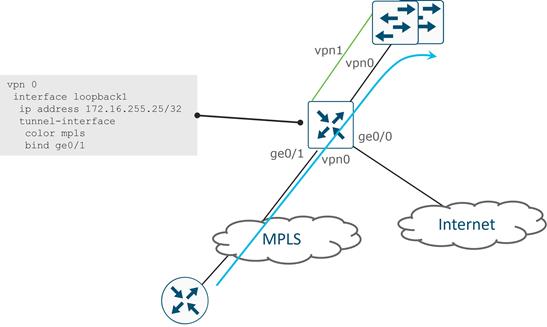
For VRRP, you can configure a priority from 1 to 254 (100 being the default), and the peer with the highest priority is elected the primary, or the active VRRP peer. If the priority is the same, then the router with the lower LAN IP address is elected the primary. It is recommended that you pick and configure the active peer, so traffic forwarding from the site is deterministic. Preemption is enabled automatically, which means if the original elected or configured primary becomes unavailable and then later become available, it will take back over as the active peer.
The VRRP primary sends advertisements by default every second, and this timer is configurable. If the backup VRRP routers miss three consecutive advertisements, then the primary is assumed to be down and a new primary is elected.
When the WAN becomes unreachable for a particular WAN Edge router, you want to ensure that it gives up the role as the VRRP active router. There are two main options for this:
● Track on OMP – In this case, the OMP sessions to the SD-WAN Controllers are monitored and when the sessions are lost, a new VRRP primary is elected. Note that before the VRRP primary is elected, the OMP hold timer must expire. The hold timer by default is 60 seconds and can be adjusted. Keepalives are sent every 1/3 of this OMP hold timer value, and when three are missed, the OMP session is considered down.
● Track on a prefix list – In this case, one or more prefixes are tracked in a list. When all the prefixes in the list are lost from the routing table, VRRP failover occurs without waiting for the OMP hold timer to expire. Tracking on a prefix list is preferred because convergence occurs more quickly than tracking on OMP.
| Tech tip |
| When tracking on OMP or a prefix list, VRRP becomes inactive in cases where OMP goes down or prefixes disappear from the routing table. If this occurs on both WAN Edge routers at the same time, this can result in the default gateway being deactivated in both routers. It is recommended to only configure Track OMP or Track Prefix List on your primary router. If configured on both routers at a site, the site may lose connectivity if control connections go down. |
Data Center
SD-WAN Edge deployment should start in the data center. When deploying, it is important to not impact normal traffic flow to and from the data center for non-SD-WAN sites, so it is not common for CE routers to be immediately replaced by SD-WAN routers at the start of an SD-WAN deployment. It is recommended that the data center is used as a transit for SD-WAN and non-SD-WAN traffic if possible during the migration. See the Cisco SD-WAN Migration Guide for more information.
It is recommended to not put WAN Edge routers inline at the data center site. You don’t want to interrupt traffic when deploying or make the WAN Edge routers the bottleneck for all traffic SD-WAN and non-SD-WAN traffic. Use WAN Edge for SD-WAN traffic, non-SD-WAN traffic can come into the CE and route to the core. It is recommended that the VPN 0 interfaces connect into CE routers for MPLS and firewalls for Internet if possible. On the WAN Edge, connect to both transports for each WAN if possible. TLOC extensions are not commonly used in the data center. You do not want traffic to be greatly impacted by a link or device failure.
On the LAN side, connect interfaces to the same switch the CE routers connect with (Core or WAN Services block). It is preferred to use BGP (eBGP preferred over iBGP) in the LAN if it already exists, otherwise the SD-WAN router can integrate with OSPF or EIGRP (in the case of IOS XE SD-WAN routers) if it is already present on the LAN side. Try to reduce complexity as you don’t necessarily want to make the core a redistribution point. Integrate with CE routing if necessary.
Note that IPsec tunnels are built automatically between locations with different site-ids. If you have a DCI between two data centers, the DCI should be used to transfer traffic between the sites, and IPsec tunnels should not be formed across transports (to avoid routing loops) . You can prevent tunnels from forming between sites by modifying the centralized policy. It is not recommended to run SD-WAN over the DCI links between data centers.

Branches
For branch designs, keeping the design simple is important. Integrate with the LAN core if possible, and only integrate with the CE when necessary. It may be necessary to preserve the CE for voice services or for certain connectivity types. It is recommended to replace CE routers wherever possible.
It is recommended to incorporate underlay and overlay routing at hub/data center sites only and avoid at branch sites if possible. At a branch site, it is recommended to completely convert the site to SD-WAN. Incorporating underlay routing at a branch so direct communication can occur to non-SD-WAN sites increases complexity, can introduce routing loops and cause the branch to become a transit site for traffic if not implemented properly. Voice has a 300ms trip latency budget before the human ear can detect it, which in most cases is not an issue while migrating.
SD-WAN Service-Point Deployment
There may be branches that require features or connectivity that are not yet fully supported by a pure SD-WAN deployment with IOS XE SD-WAN or vEdge routers. A combination of an IOS XE router, along with a WAN Edge SD-WAN router can be deployed together to cover the features necessary in the interim.
LAN-Facing Requirements
On the LAN-facing side of a branch, there may be requirements not supported by a WAN Edge router that can be supported by an IOS XE router such as an ISR4k. This may include voice support, WAN optimization, service route tracking, security, or EEM. An ISR 4k router on IOS XE code can be deployed on the LAN side of an SD-WAN router to fulfill the additional requirements. This combination of an IOS XE router with a WAN Edge router could even be virtualized on a single physical device, such as the ENCS platform.
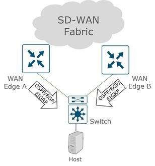
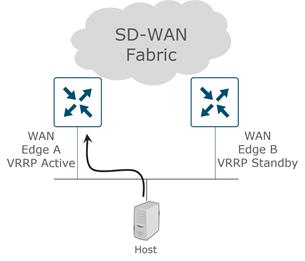
WAN-Facing Requirements
Similar to the LAN-facing requirements, there may be requirements on the WAN-facing side of a branch that are not supported by a WAN Edge router that can be supported by an IOS XE router. This might include ATM, Frame Relay, EEM, and ECMP routing to a cloud SIG. An ISR 4k router on IOS XE code can be deployed on the WAN side of an SD-WAN router to fulfill the additional requirements.
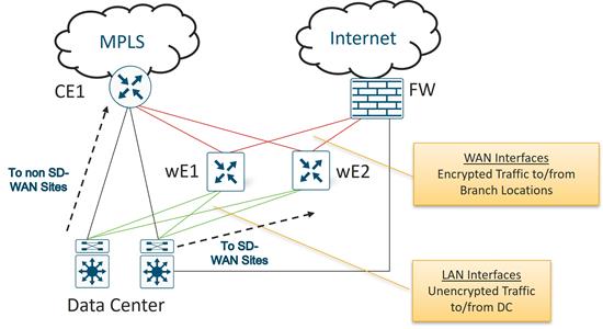
Common Branch Deployments
The following are some common branch deployments. This is not an exhaustive list.
Single WAN Edge
The following deployments depict a single WAN Edge router deployed at a branch site. All are connected to at least two transports, and the middle deployment is connected through a CE router in order to reach the MPLS transport. The switches can be configured as either layer 2 or layer 3 switches.
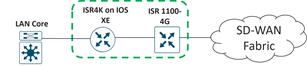
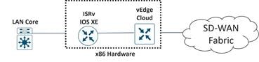
Dual WAN Edge
The following deployments depict dual-WAN Edge routers deployed at a branch site. Each WAN Edge router connects to one transport and the WAN Edge routers are connected directly for the TLOC Extension links.
In the L2 switch deployment, each WAN Edge router is connected to one LAN Switch via an 802.1 VLAN trunk. A WAN Edge router does not connect to each switch (in the same VLANs) because a bridge interface would need to be implemented on the WAN Edge router, which increases the configuration complexity. Note that there is also no spanning-tree protocol support on the WAN Edge routers.
In the L2 switch stack deployment, each WAN Edge router connects to each switch in the two-switch stack via a port-channeled 802.1 VLAN trunk. Port-channels/EtherChannels are supported on the service-side of WAN Edge routers starting in version 20.6.1/17.6.1a.
In the L3 switch deployment, a routing protocol (OSPF, BGP, or EIGRP for IOS XE SD-WAN routers) is run between the switch and the WAN Edge routers. RIPv2 routing protocol for IPv4 is supported starting in 20.7.1/17.7.1a.
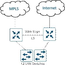
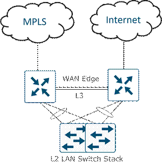

Application Visibility
Application visibility is a key component of SD-WAN and an enabler of several use cases. Application visibility allows data traffic to be inspected and analyzed in detail and allows protocols and applications to be learned and classified using advanced techniques such as stateful inspection and behavioral and statistical analysis. You can then use application classification in different features, such as monitoring, security policy, Cloud onRamp for SaaS, application-aware routing policy, quality of service (QoS), and more. Some features require application visibility, such as Cloud onRamp for SaaS, while for other features, it is optional to use application matching in policies.
vEdge and IOS XE SD-WAN routers currently use different classification engines. vEdge routers use Deep Packet Inspection (DPI) using the Qosmos classification engine while IOS XE SD-WAN routers use NBAR2. While the interoperability of both platforms is supported, there may be slight differences in application classification, so this might affect the policies that are created.
SD-AVC
SD-AVC also implements application recognition for visibility and policy configuration but operates as a centralized network service. As opposed to running DPI or NBAR2 alone, which is strictly localized information, SD-AVC can aggregate application data from multiple devices in the network and can synchronize application states between network nodes. SD-AVC runs as a container on the SD-WAN Manager starting in version 18.4. SD-AVC is supported only on IOS XE SD-WAN routers at this time using a linux container as a virtual service beginning in the 16.10.1 version of code.
Traffic Symmetry for Application Visibility
For the localized application visibility features (DPI and NBAR2) to be able to classify most application traffic, it is important that the WAN Edge router sees network traffic in both directions. In dual-WAN Edge sites without any policy enabled, equal cost paths exist over each transport and to each WAN Edge router, and network traffic is hashed depending on fields in the IP header. Traffic is unlikely to always be forwarded to the same WAN Edge router in both the LAN-to-WAN direction and the WAN-to-LAN direction. To maintain symmetric traffic, it is recommended to set up routing so that traffic prefers one WAN Edge over another at dual-WAN Edge router sites.
Note that traffic symmetry is not required with SD-AVC since it is a centralized network service and application states are synchronized between network nodes.
To ensure symmetry, traffic needs to prefer one router in both directions, from the LAN to the WAN and from the WAN to the LAN. There are different ways to accomplish this.
To influence traffic in the LAN to WAN direction:
● For VRRP, use VRRP priority to prefer one WAN Edge router over the other. The router with the highest priority is preferred.
● For OSPF, use the cost metric, configured either on the interface of the neighboring switch/router itself or through a route policy on the WAN Edge router that modifies the metric of routes redistributed from OMP to OSPF. The link with the lowest cost is the preferred path.
● For EIGRP, use the delay metric configured on the interface of the neighboring switch/router.
● For BGP, use a route policy and set AS path prepend or multi-exit discriminator (MED) on routes redistributed from OMP to BGP.
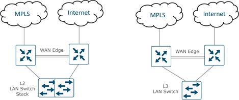
To influence traffic in the WAN-to-LAN direction over the overlay, you can influence an OMP attribute (including OMP route preference) or set the TLOC preference under the tunnel interface. When BGP or OSPF is redistributed into OMP, the MED setting for BGP and the cost for OSPF is automatically translated into the OMP origin metric, which is used in the decision making for picking the best route. While OMP metric can be used to influence traffic over the SD-WAN overlay, it is more common to use OMP route preference and TLOC preference to influence traffic.
Some common methods to influence traffic for the WAN-to-LAN direction:
● For BGP, use a route-policy and set MED (metric) on routes inbound from the LAN BGP neighbors
● For OSPF, use WAN Edge router interface cost to set the metric on routes coming into the LAN interface
● For any WAN Edge router, including VRRP routers, use TLOC preference to influence which is the preferred WAN Edge through the WAN overlay
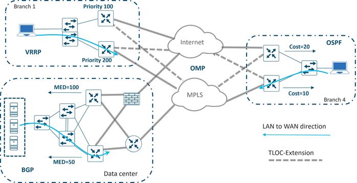
WAN Edge Scale
It is important to properly size the type of WAN Edge router for a particular site. To properly size, it is important to understand the throughput limits, the sustained number of active static tunnels, VPN segments, and number of routes the device can handle.
IPsec Tunnels
By default, and in absence of centralized policy and restrict settings, WAN Edge routers attempt to form IPsec tunnels with all WAN Edge routers’ remote TLOCs, regardless of color. Depending on the size of the network, this may not be desirable due to the type of routers at the remote sites and the number of tunnels they each can support. One way to limit the number of tunnels at the branch sites is to configure a hub and spoke topology or partial mesh topology using centralized control policies or tunnel groups, ensuring the hub site WAN Edge routers can accommodate the required tunnel scale.
Horizontal Scaling
There may be times that more throughput or IPsec tunnels are required at a site than can be supported by a single router. In those cases, WAN Edge routers can scale horizontally. When designing for these networks, keep in mind that on the SD-WAN Controller, the number of equal-cost paths for a prefix is limited to 16, and the default is set to 4.
Remote Site Groupings
The following diagram illustrates an example of horizontal scaling in the data center to accommodate more tunnels and throughput on the head-end routers. All remote sites are divided into different site groups. In each data center, a pair of WAN Edge routers, one primary and one secondary, is deployed for each site group. Tunnels are restricted between pairs of data center routers and respective site groups using centralized control policies. Tunnel groups can also be utilized in large scale designs to create site groupings to different head-end routers.
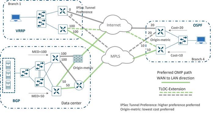
VPN Groupings
Another way to achieve horizontal scaling is to split traffic between WAN Edge routers by distributing VPNs among with routers. This allows you to scale at branches that might need more bandwidth in addition to the head-end sites. The following diagram shows an example of this. Three groups of VPNs are created. In each data center, a pair of WAN Edge routers, one primary and one secondary, is deployed for each distinct set of VPNs. Any number of branch routers can be split among VPNs. Remote site routers can have full tunnel connectivity to all of the head-end routers or they can be filtered using centralized control policies depending on the VPNs being serviced.
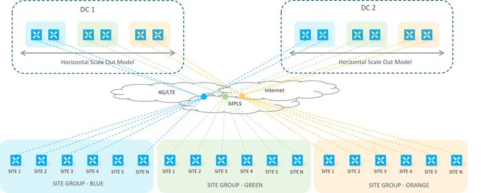
Multi-Regional Deployment
For large-scale WAN Edge deployments, WAN Edge routers are often grouped within regions. Inside the regions, the WAN Edge routers are either fully meshed together, or configured in a hub-and-spoke topology. Hub-and-spoke topologies save on tunnel capacity since tunnels are only built to the hub routers. Border WAN Edge routers act as hub routers within regions and connect to other border routers in other regions. TLOCs that belong inside the region are not permitted in the network between regions, and in order for a WAN Edge router in one region to send traffic to another WAN Edge router in a different region, traffic must traverse the hub routers.
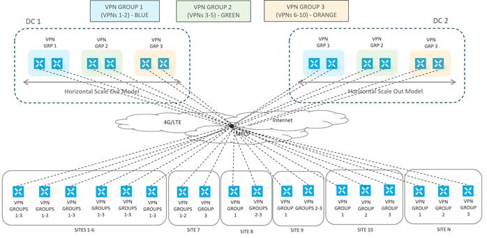
The SD-WAN Manager is the Cisco Catalyst SD-WAN centralized GUI that allows management of the SD-WAN network from end to end from a single dashboard.
Software
When choosing software versions for control components and WAN Edge routers, ensure that all code versions are compatible. What you choose to use for the SD-WAN Manager code version dictates what versions are supported for the various control components and WAN Edge routers. See the Controller Compatibility Matrix at https://www.cisco.com/c/en/us/td/docs/routers/sdwan/release/notes/compatibility-and-server-recommendations/comp-matrix-intro-chapter-map.html for the listing of code version compatibility. Note that even if code versions are listed as compatible, certain features that are supported in the latest version of the SD-WAN Manager may not be supported on the corresponding compatible control component or WAN Edge router software version. You may get errors when you push unsupported features from the SD-WAN Manager to those devices.
Ensure to check the release notes before upgrading to a new code version. The release notes contain information about new features, open bugs, and any ROMmon requirements for IOS XE SD-WAN devices: https://www.cisco.com/c/en/us/support/routers/sd-wan/products-release-notes-list.html
Upgrades
When moving to a particular code version, it is important to first upgrade code on the SD-WAN Manager, then on the other control components (SD-WAN Validators and SD-WAN Controllers), and lastly, on the WAN Edge routers. Ensure the SD-WAN Manager and other control components are at the proper code version before bringing the WAN Edge routers onto the targeted code version. Also be certain to check the compatibility of the code on both control components and WAN Edge routers before moving forward with an upgrade. The WAN Edge routers can be upgraded once online or as a last part of the ZTP or PnP process, or even manually before deployment, if needed.
Once desired code versions are loaded into the software repository, there are two parts to upgrading software, upgrading and activating. Upgrading installs the code version onto the WAN Edge device, and activating it reboots the device and begins running the new code version. These steps can be done separately, or activating can occur immediately after upgrading.
| Tech tip |
| As a best practice, it is highly recommended to install software on SD-WAN devices during non-production times because it may impact the performance of production traffic depending on the bandwidth of the transports at any given site. Once upgraded, it is not possible to downgrade the SD-WAN Manager to a lower major release. For example, if you are running an 18.3.x release, you cannot downgrade to an 18.2.x or lower release. While you may be able to install a lower code version onto the SD-WAN Manager server, you will not be able to activate it. Take VM snapshots before upgrading so that you can restore on the lower code version if needed. |
The following are best practices when upgrading software. While you don’t have to follow every procedure exactly, it is important to develop a plan to mitigate downtime and to have a plan for backing out in case of unforeseen circumstances.
1. (required) Upgrade and activate the SD-WAN Manager first.
2. (highly recommended) Upgrade and activate half of the SD-WAN Validators and let them run stable for a time (24 hours for example) before upgrading and activating the other half. The SD-WAN Validators should be updated after the SD-WAN Manager server and before the SD-WAN Controllers.
3. (highly recommended) Upgrade and activate half of the SD-WAN Controllers and let the Controllers run stable for a time (24 hours for example) before upgrading and activating the other half. The SD-WAN Controllers should be updated after the SD-WAN Validators and before the WAN Edge routers.
4. Break up the WAN Edge routers into different upgrade groups. You can identify them with a tag in the device groups field in the system template. Target a test site or multiple test sites and put those WAN Edge routers into the first upgrade group. In dual WAN Edge sites, put each router into a different upgrade group and do not upgrade both of them at the same time. All WAN Edge routers in an upgrade group can be upgraded in parallel (up to 32 WAN Edge routers), however, take into account the ability for the SD-WAN Manager or a remote file server to be able to handle the concurrent file transfers to the WAN Edge routers.
5. Upgrade and activate the first upgrade group and let the code run stable for a predetermined amount of time, then proceed to upgrade and activate the additional upgrade groups over a predetermined timeframe. When upgrading using the SD-WAN Manager, you can upgrade using a code image that is directly loaded onto the SD-WAN Manager or a remote SD-WAN Manager, and you can also upgrade using a code image located on a remote file server.
| Tech tip |
| Note that there were security enhancements implemented in vEdge code 18.2.0 which restricts the ability to downgrade images. You cannot install a software version release 17.2 or earlier on a vEdge router running release 18.2.0 or later. You can activate an older image already installed, however. Once you install and activate release 18.3 on a vEdge router, after one week, all releases 18.1 and earlier are removed from the router and you cannot reinstall them. With release 18.4, all releases 18.1 and earlier are removed after 20 minutes and you cannot reinstall them. |
Configuration Templates
Configurations and policies are applied to WAN Edge routers and SD-WAN Controllers which enable traffic to flow between the data center and the branch or between branches. An administrator can enable configurations and policies through the command-line interface (CLI) using console or Secure Shell (SSH) on the WAN Edge device, or remotely through the SD-WAN Manager GUI.
To configure a WAN Edge device or control component on the network using the SD-WAN Manager GUI, an administrator applies a device template to a WAN Edge router or multiple WAN Edge routers. These templates can be CLI-based or feature-based. While you can create CLI-based templates, we recommend feature-based templates because they are modular, more scalable, and less error-prone. Each device template is made up of several feature templates that describe the interface configurations, tunnel configurations, and local routing behavior.
| Tech tip |
| In order to apply an SD-WAN Manager centralized policy to the network, the SD-WAN Controllers must be managed by the SD-WAN Manager. You accomplish this by attaching a CLI or feature-based device template to them. |
Templates are extremely flexible, and there are a number of approaches to putting templates together. You can choose to have more variables inside your template, which will result in less feature templates, or you can have less variables but more feature templates. For example, you can choose to enable NAT as a variable or a global value. You can create one interface feature template and choose to enable or disable NAT through a variable, or you can create two different feature templates, one with NAT disabled and one with NAT enabled, and choose the most appropriate feature template to use, depending on the device template. In any case, you should add a detailed description of each feature and device template in detail in the GUI and create very descriptive variable names so that it is very clear what each template and variable is.
When designing configuration templates, it is helpful to think about how operations may interact with the templates on a day-to-day basis. It might be useful to use variables for interface names so that interfaces can be moved for troubleshooting purposes, without having to create new feature templates to accomplish it (or interrupt other devices using the same feature template). It also might be helpful to create variables for states of interfaces and routing protocols for troubleshooting reasons, such as allowing the disabling of an interface or a BGP neighbor by just changing a variable.
| Tech tip |
| Starting in the SD-WAN Manager version 20.1, feature templates can no longer be shared between vEdge and IOS XE SD-WAN devices. For feature templates that are shared, you are able to upgrade to SD-WAN Manager 20.1 but are not able to make modification or edits to shared feature templates. You should make copies of shared feature templates, then migrate IOS XE SD-WAN devices to device templates that reference these new feature templates. A script to assist in this feature template migration is available. See https://www.cisco.com/c/en/us/td/docs/routers/sdwan/configuration/system-interface/ios-xe-17/systems-interfaces-book-xe-sdwan/c-template-migration.pdf for more detail. |
Device Templates
Device templates are specific to only one WAN Edge model type, but you may need to create multiple device templates of the same model type due to their location and function in the network. Each device template references a series of feature templates which makes up the entire configuration of the device. A device template configuration cannot be shared between WAN Edge models, but a feature template can span across several model types and be used by different device templates.
The following figure illustrates device template components. The device template is made up of feature templates grouped into the following sections:
● Basic information - This section includes system, logging, AAA, OMP, BFD, security, and NTP feature templates.
● Transport and management VPN - This section includes the templates used to configure VPN 0 (underlay) and VPN 512 (out-of-band management), which includes BGP, OSPF, VPN interface, VPN interface cellular, VPN interface GRE, and VPN interface PPP feature templates.
● Service VPN - This section includes the templates used to configure the service VPNs, which contains the BGP, IGMP, Multicast, OSPF, EIGRP, PIM, VPN interface, VPN interface bridge, VPN interface GRE, VPN interface IPsec, VPN interface Natpool, and DHCP server feature templates.
● Cellular – This section includes the templates used to configure the cellular or T1/E1 controller.
● Additional templates - This section includes banner, Simple Network Management Protocol (SNMP), bridge, localized policy, and security policy templates.
| Tech tip |
| The feature template support in each device template varies depending on the SD-WAN platform. |
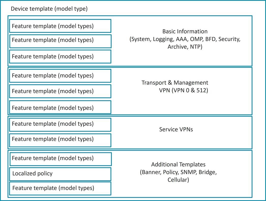
Feature Templates
The following is a brief description of some of the different feature templates and a subset of the information each will allow you to configure.
● System - Configure basic system information, such as site ID, system IP, time zone, hostname, device groups, GPS coordinates, port hopping, and port offset.
● Logging - Configure logging to disk and/or to a remote logging server.
● AAA - Specify the authentication method and order and configure Radius, TACACs, or local authentication, including local user groups with different read/write permissions.
● BFD - Specify the BFD app-route multiplier and poll interval and specify the hello and BFD multiplier for each transport.
● OMP - Change the graceful restart timers and advertisement timers and hold timers; change the number of paths advertised; configure an AS overlay number; choose which local protocols will be advertised into OMP; and change the number of equal-cost paths installed in the WAN Edge router.
● Security - Change the rekey time, anti-replay window, and authentication types for IPsec.
● Archive (optional) - Archive the full running configuration onto a file server within a time period specified.
● NTP (optional) - Configure NTP servers and authentication if required.
● VPN - Change the ECMP hash, add DNS servers, advertise protocols (BGP, static, connected, OSPF external) from the VPN into OMP, and add IPv4 or v6 static routes, service routes, and GRE routes.
● BGP (optional) - Configure the AS number, router ID, distance, maximum paths, neighbors, redistribution of protocols into BGP, hold time, and keepalive timers.
● OSPF (optional) - Configure router ID, distance, areas, OSPF interfaces, reference bandwidth, default information originate, metrics, metric type, and SPF timers.
● VPN Interface configuration - Configure an interface name, the status of the interface, static or dynamic IPv4 and v6 addressing, DHCP helper, NAT, VRRP, shaping, QoS, ingress/egress access control list (ACL) for IPv4 and 6, policing, static Address Resolution Protocol (ARP), 802.1x, duplex, MAC address, IP maximum transmission unit (MTU), Transmission Control Protocol maximum segment size (TCP MSS), TLOC extension, and more. In the case of the transport VPN, configure tunnel, transport color, allowed protocols for the interface, encapsulation, preference, weight, and more.
● VPN interface bridge (optional) - Configure layer 3 characteristics of a bridge interface, including IPv4 address, DHCP helper, ACLs, VRRP, MTU, and TCP MSS.
● DHCP server (optional) - Configure DHCP server characteristics, such as address pool, lease time, static leases, domain name, default gateway, DNS servers, and TFTP servers.
● Banner (optional) - Configure the login banner or message-of-the-day banner.
● Policy (optional) - Attach a localized policy.
● SNMP (optional) - Configure SNMP parameters, including SNMP device name and location, SNMP version, views, and communities, and trap groups.
● Bridge (optional) - Define layer 2 characteristics of a bridge, including the VLAN ID, MAC address aging, maximum MAC addresses, and physical interfaces for the bridge.
Routing protocol templates, such as BGP, OSPF, or EIGRP and VPN interface templates are configured under a VPN. DHCP server feature templates are configured under a VPN interface.
Configuring Parameters
An administrator uses the SD-WAN Manager to configure device and feature templates, specifying variables where needed since templates can apply to multiple WAN Edge devices that have unique settings.
When configuring values of parameters inside of feature templates, there is often a drop-down box that gives you three different types of values:
● Global - When you specify a global value, you specify the desired value, either by typing the value into a text box, selecting a choice from a radio button, or selecting a value from a drop-down box. Whatever value you select will be applied to all devices the feature template is applied to.
● Device-specific - When you specify a device-specific value, you will create a variable name. The value for this variable will be defined when the device template is applied.
● Default - When you specify a default value, a default value will be applied to all devices the feature template is applied to. If there is a specific value, it will appear in a textbox in grey scale.
In the illustration below, Timezone is shown as a global, device-specific, or default value. A variable name is entered when specifying the device-specific value.
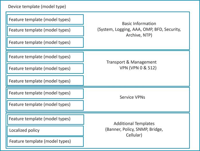
| Tech tip |
| Within each feature template, you can use the same variable name for two different parameter values, but they will be treated like two separate variables. Descriptive and unique variable names are important so that it is clear what values need to be entered when the device template is applied to a device. Variables with the same name in different templates are also different variables and you cannot share them across templates. |
Optional Configurations
Beginning in the 18.2 SD-WAN Manager code version, many individual feature template configurations can be now marked as optional. This allows you to use a single feature template for multiple routers with slight configuration differences, as opposed to defining separate feature templates altogether. As an example, if you have one site that uses static routes but another site does not, you could make the static routes optional in the VPN template and then use the same template in both routers instead of making one template with static routes included and another template with no static routes.
Deploying Device Templates
Once feature templates are configured, the device template configuration is completed by referencing the desired feature template in each configuration category (system, AAA, BFD, VPN, VPN interface, etc.). Once a device template is configured, it can be attached to a specific WAN Edge device. Once attached, you will be required to fill in the values for any variables in the template for each WAN Edge the template will apply to before the configuration can be deployed. You can enter values through the SD-WAN Manager GUI directly, or by filling out a .csv file that can be uploaded. The .csv file method allows you to deploy a large number of WAN Edge routers quickly and more easily. The SD-WAN Manager will then modify the configuration of the targeted WAN Edge devices in the database and then push out the entire configuration to the intended WAN Edge routers on the network.
When making an update to a feature or device template, the application will happen immediately if there are devices attached to those templates. If the configuration gets pushed out and if there is an error, such as an incorrect value format or a reference to a loopback interface that doesn't exist, the template configuration rolls back to its previous state before the edit.
Policies
Policies are an important part of the Cisco Catalyst SD-WAN Solution and are used to influence the flow of data traffic among the WAN Edge routers in the overlay network. Policies apply either to control plane or data plane traffic and are configured either centrally on the SD-WAN Controllers (centralized policy) or locally (localized policy) on WAN Edge routers.
Centralized control policies operate on the routing and TLOC information and allow for customizing routing decisions and determining routing paths through the overlay network. These policies can be used in configuring traffic engineering, path affinity, service insertion, and different types of VPN topologies (full-mesh, hub-and-spoke, regional mesh, etc. Localized control policies allow you to affect routing policy at a local site, specifically through OSPF or BGP route maps and prefix lists.
Data policies influence the flow of data traffic through the network based on fields in the IP packet headers and VPN membership. Centralized data policies can be used in configuring application firewalls, service chaining, traffic engineering, quality of service (QoS), and Cflowd. Another centralized data policy is application-aware routing, which selects the optimal path based on real-time path performance characteristics for different traffic types. Localized data policies allow you to configure how data traffic is handled at a specific site, such as ACLs, QoS, mirroring, and policing. Some centralized data policy may affect handling on the WAN Edge itself, as in the case of app-route policies or a QoS classification policy. In these cases, the configuration is still downloaded directly to the SD-WAN Controllers, but any policy information that needs to be conveyed to the WAN Edge routers is communicated through OMP.
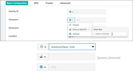
Configuring Localized Policy
There are three steps for configuring and applying localized policy:
In the SD-WAN Manager GUI, create the localized policy under Configuration>Policies and select the Localized Policy tab. Before Release 18.2, the policy is added as a CLI policy. Starting in Release 18.2, a policy configuration wizard was created to assist with policy creation.
In the device template, under the Additional Templates section next to Policy, reference the name of the localized policy.
Reference any policy components, like route policies and prefix lists, inside the feature templates.
When you are creating a device template and referencing a feature template that already has a route policy or prefix list or another localized policy component configured in it, you must have a policy name referenced in the device template before you can create or update the device template. If a device is already attached to an existing device template, you must first attach a localized policy to the device template before referencing any localized policy elements within the feature templates that are associated with that device template.
You can only apply one localized policy to a WAN Edge device. Within this policy, you will create both control and data policies components; prefix-lists, route-policies, as-path lists, community-lists, QoS class-maps, qos-map policies, mirror and policing policies, rewrite-rule policies, and access lists will all be included in this one localized policy.
Configuring Centralized Policy
When configuring centralized policy in the SD-WAN Manager GUI, there are three main components:
● Lists - Lists are used to group related items so you can reference them as a group. They are used when applying policy or used in matching or actions within the policy definitions. You can create lists for applications, color, data prefixes, policers, prefixes, sites, SLA classes, TLOCs, and VPNs. Data prefixes are used in data policies to define data prefixes, and prefixes are used in control polices to match on route prefixes.
● Policy definition - The policy definitions control the aspects of control and forwarding. Within the policy definition is where you create policy rules, specifying a series of match-action pairs which are examined in sequential order. There are several types of policy definitions: app-route policy, cflowd-template, control-policy, data-policy, and a vpn-membership policy.
● Policy application - The policy is applied to a site list.
There are several different types of policy definitions:
● App-route policy - Allows you to create an application-aware routing policy which tracks path characteristics such as loss, latency, and jitter. Traffic is put into different SLA categories (loss, delay, and jitter), and traffic is directed to different paths depending on the abilities to meet the SLA categories.
● Cflowd template - Allows you to enable cflowd, which sends sampled network data flows to collectors.
● Control policy - Operates on the control plane traffic and influences the routing paths in the network.
● Data policy - Influences the flow of data traffic based on the fields in the IP packet header.
● VPN membership policy - Can restrict participation in VPNs on WAN Edge routers and the population of their route tables.
Control policy examines the routes and TLOC attributes in the routing information and modifies attributes that match the policy. This policy is unidirectional and can be applied to a site list in an inbound or outbound direction. The direction is from the perspective of the SD-WAN Controller. A policy applied to a site list in the inbound direction means that policy would affect routes coming from the sites on the site list and actions would be applied on the receive side of the SD-WAN Controller. A policy applied to a site list in the outbound direction means the policy would affect routes going to the sites on the site list and actions would be applied to the sending side of the SD-WAN Controller.
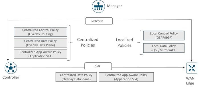
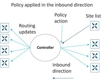
No direction is set with app-route polices – this policy is sent to the WAN Edge router via OMP and applied to the WAN Edge as traffic moves in the direction from LAN to WAN. No direction is set with cFlowd and VPN policy as well. Data policy, however, is directional from the perspective of the WAN Edge. You can apply this either from-service, from-tunnel, or all.
Note that you can create several centralized polices within the SD-WAN Manager GUI, but only one can be activated at a time on the SD-WAN Controller. Inside the centralized policy, you will be able to create several different policy definitions that make up the centralized policy, for example, app-route, cflowd, control, data, and vpn-membership policies. Note that with a given site list, you are restricted to one of each type of policy, but you can have a different control policy in each direction (inbound and outbound). When creating site ID lists for the purpose of applying policy definitions, you must not overlap site IDs in different lists.
Order of Operations
Following is the order of operations on a packet as it traverses from service VPN to transport VPN on a WAN Edge router:
1. Local policy/configuration - includes QoS classification, policer, and marking
2. Centralized application-aware routing policy
3. Centralized data policy - includes QoS classification, policer, marking, and path selection
4. Routing/forwarding
5. Scheduling and queueing
6. Local policy shaping and ACL - includes shaping, re-marking, and policer
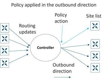
From the ordering, it's possible for a centralized data policy to overwrite the actions of a local data policy configuration, and it's also possible for a centralized data policy to influence the path selection that is different than what was chosen as part of the application-aware routing policy. Keep this information in mind as you define the policies for the network.
It is important to plan out your SD-WAN deployment carefully, as to make it easier for configuration, day-to-day operations, and maintenance. Following are some considerations.
Port Numbering
It is recommended to have a port-numbering scheme that is consistent throughout the network. Consistency assists in easier configuration and troubleshooting.
In addition, the default factory configuration of a WAN Edge router specifies certain ports in VPN 0 for DHCP so the WAN Edge can automatically obtain a DHCP address, resolve DNS, and communicate with the ZTP or PnP server. So, if you utilize ZTP or PnP, be sure this port has reachability to the DHCP and DNS servers by connecting them to the most appropriate place in the network.
System IP
System IP is a persistent, system-level IPv4 address that uniquely identifies the device independently of any interface addresses. It acts much like a router ID, so it doesn't need to be advertised or known by the underlay. A best practice, however, is to advertise this system IP address in the service VPN and use it as a source IP address for SNMP and logging, making it easier to correlate network events with the SD-WAN Manager information. A system IP address is required to be configured in order for a WAN Edge router to be authenticated by the control components and brought into the overlay network.
A logical scheme for your system IP addresses is recommended to make sites more easily recognizable.
Site ID
A site ID is a unique identifier of a site in the SD-WAN overlay network with a numeric value 1 through 4294967295. This ID must be the same for all the WAN Edge devices that reside at the same site. A site could be a data center, a branch office, a campus, or something similar. A site ID is required to be configured in order for a WAN Edge router to be authenticated by the control components and brought into the overlay network. By default, IPsec tunnels are not formed between WAN Edge routers within the same site.
A site ID scheme should be chosen carefully, as this makes it easier to apply policy. When you apply policy, you apply policy to a list or range of site IDs (ex. 100,200-299), and there is no wildcard support.
Although there are several different ways to organize a site ID scheme, the following table provides an example of a scheme that uses six digits.
Table 7. Cisco Catalyst SD-WAN site ID scheme
| Digit |
Representation |
Examples |
| 1 |
Country/Continent |
1=North America, 2=Europe, 3=APAC |
| 2 |
Region |
1= US West, 2= US East, 3=Canada West, 4=Canada East |
| 3 |
Site type |
0=Hub locations, 1=Type 1 sites, 2=Type 2 sites, 3= Type 3 sites, 4= Type 4 sites, 5= Future use |
| 4-6 |
Store, site, branch number, or any other ID specifier |
001, 002, 003, etc. |
Grouping according to geography is helpful in cases where you might want to prefer a regional data center over another for centralized Internet access or for connectivity to hubs in other countries and regions.
Site types should be created according to types of policies applied in order to make applying policy easier. When a new site is created, just creating a site ID that falls into the matching range of a policy will automatically cause the policy to be applied to it. Some examples of how you may want to group branches according to type include:
● Branches that use a centrally located firewall or another centrally located service.
● Branches that use Direct Internet Access.
● Lower versus higher bandwidth sites since you may want different topologies for each. Low-bandwidth sites could use a hub-and-spoke topology to save bandwidth while higher bandwidth sites use a full-mesh topology.
● Different SLA and transport requirements, such as using MPLS for critical traffic, voice, and video while everything else traverses the Internet circuit, and perhaps some sites using MPLS for voice only, while everything else traverses the Internet circuit.
Obviously, you can have overlapping types, but the idea is to put them in categories that makes it easier to apply policy from a configuration perspective. It helps to think about the requirements and policies required before assigning site IDs.
Device Groups
Device groups are labels that are assigned to WAN Edge devices that can help organize and group common devices when using the SD-WAN Manager GUI for monitoring or for upgrades. Device groups allow you to filter on device lists to make managing devices easier. A WAN Edge device can belong to one or more device groups. You can organize SD-WAN devices according to type, location, or function, or you can put them into various upgrade groups during upgrade procedures.
Appendix A: References
● Cisco SD-WAN and Cloud Networking YouTube Channel
● Cisco SD-WAN Community Resources
● Cisco EN Validated Design and Deployment Guides
● Cisco Communities/SD-WAN and Cloud Networking Forum
● Cisco Catalyst SD-WAN Home Page
● Cisco SD-WAN Cloud Scale Architecture E-book
● Cisco SD-WAN Configuration Guides
● Migration Guides:
◦ Cisco SD-WAN Migration Guide
◦ IWAN to Cisco SD-WAN Migration Guide: A Customer Journey
● SD-WAN Design Guides and Case Studies:
◦ Security Policy Design Guide for Cisco IOS-XE SD-WAN Devices
◦ SD-WAN Design Case Studies Introduction
◦ SD-WAN Small Branch Design Case Study
◦ SD-WAN Large Global WAN Design Case Study
◦ SD-WAN Security Sensitive Design Case Study
◦ Cisco Cloud First Case Study – 4Dachs Consulting
◦ Cisco Cloud First Case Study – 4Dachs2 Consulting
◦ SD-WAN Remote Access Design Case Study
● Prescriptive Deployment Guides (SD-WAN)
◦ Cisco SD-WAN: Application-Aware Routing Deployment Guide
◦ Cisco SD-WAN: WAN Edge Onboarding Deployment Guide
◦ SD-WAN Administrator-Triggered Cluster Failover Deployment Guide
◦ SD-WAN Controller Certificates and Authorized Serial Number File Deployment Guide
◦ SD-WAN End-to-End Deployment Guide
● Prescriptive Deployment Guides (SD-WAN Security/SASE):
◦ Cisco SD-WAN: Enabling Firewall and IPS for Compliance
◦ SD-WAN: Enabling Direct Internet Access Deployment Guide
◦ SD-WAN Secure Direct Cloud Deployment Guide
◦ Secure Guest Access for Cisco IOS-XE SD-WAN Devices Deployment Guide
◦ Zscaler Internet Access (ZIA) and Cisco SD-WAN Deployment Guide (Manual Tunnels pre-20.3 code)
◦ Zscaler Internet Access (ZIA) and Cisco Catalyst SD-WAN (Auto Tunnels)
● Prescriptive Deployment Guides (SD-WAN/Cloud):
◦ Cisco SD-WAN Cloud onRamp for Multicloud using Google Cloud Platform
◦ Cisco SD-WAN Cloud onRamp for IaaS using Azure Deployment Guide
◦ Extending Cisco SD-WAN into AWS with Cisco Cloud onRamp for IaaS and TGW Interconnection
◦ Extending the Cisco SD-WAN Fabric into Azure with Cisco Cloud onRamp for Multi-Cloud